Effect of Partial Blockages in Simulated LMFBR Fuel Assemblies
Contact: Vasileios Kyriakopoulos, vasileios.kyriakopoulos.at.inl.gov
Model link: THORS edge blockage Subchannel Model
Information on the THORS facility and experiments can be found in the following sources: (Fontana et al., 1973),(Han, 1977), (Jeong et al., 2005). The SCM model's geometry and subchannel/rod index notation is shown in Figure 1.
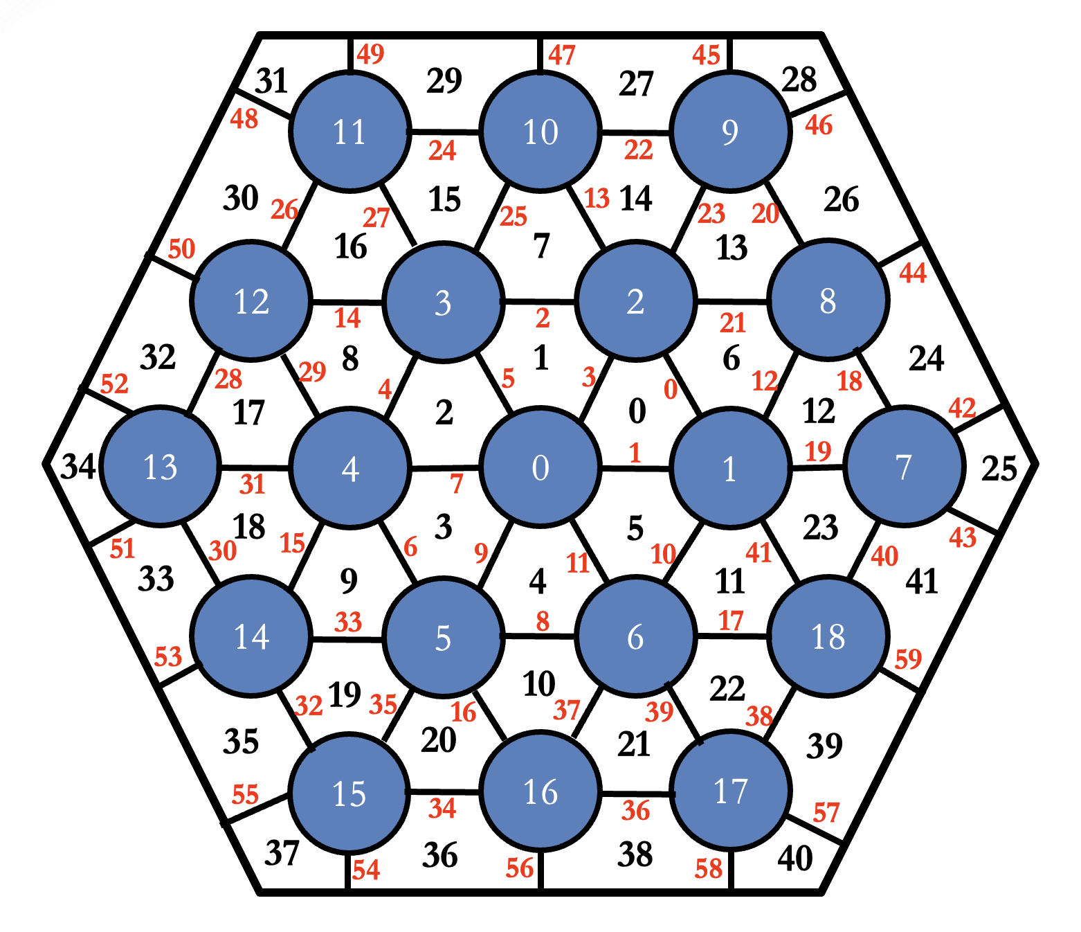
Figure 1: SCM model cross-section of THORS bundle and index notation
(white: fuel pin index; black: subchannel index; red: gap index).
Edge blockage of 14 channels in 19-pin sodium-cooled bundles
THORS bundle 5B has the same fuel configuration as bundle 2B, except that 0.0711-cm-diam wire-wrap spacers are used to separate the peripheral pins from the duct wall. The half-size spacers are used to reduce the flow in the peripheral flow channels and to cause a flatter radial temperature profile across the bundle. It also means that the flat-to-flat distance is reduced appropiately. The pins have a heated length of . A 3175-cm-thick stainless steel blockage plate is located above the start of the heated zone to block edge and internal channels along the duct wall. The test section layout is shown in Fig Figure 2. The experimental parameters for the chosen case are presented in Table 1. SCM modeled the THORS bundle 5B blockage with a % area reduction on the affected subchannels and a local form loss coefficient of . was set to as in the previous case. The SCM model's geometry and subchannel/pin index notation is shown in Figure 1.
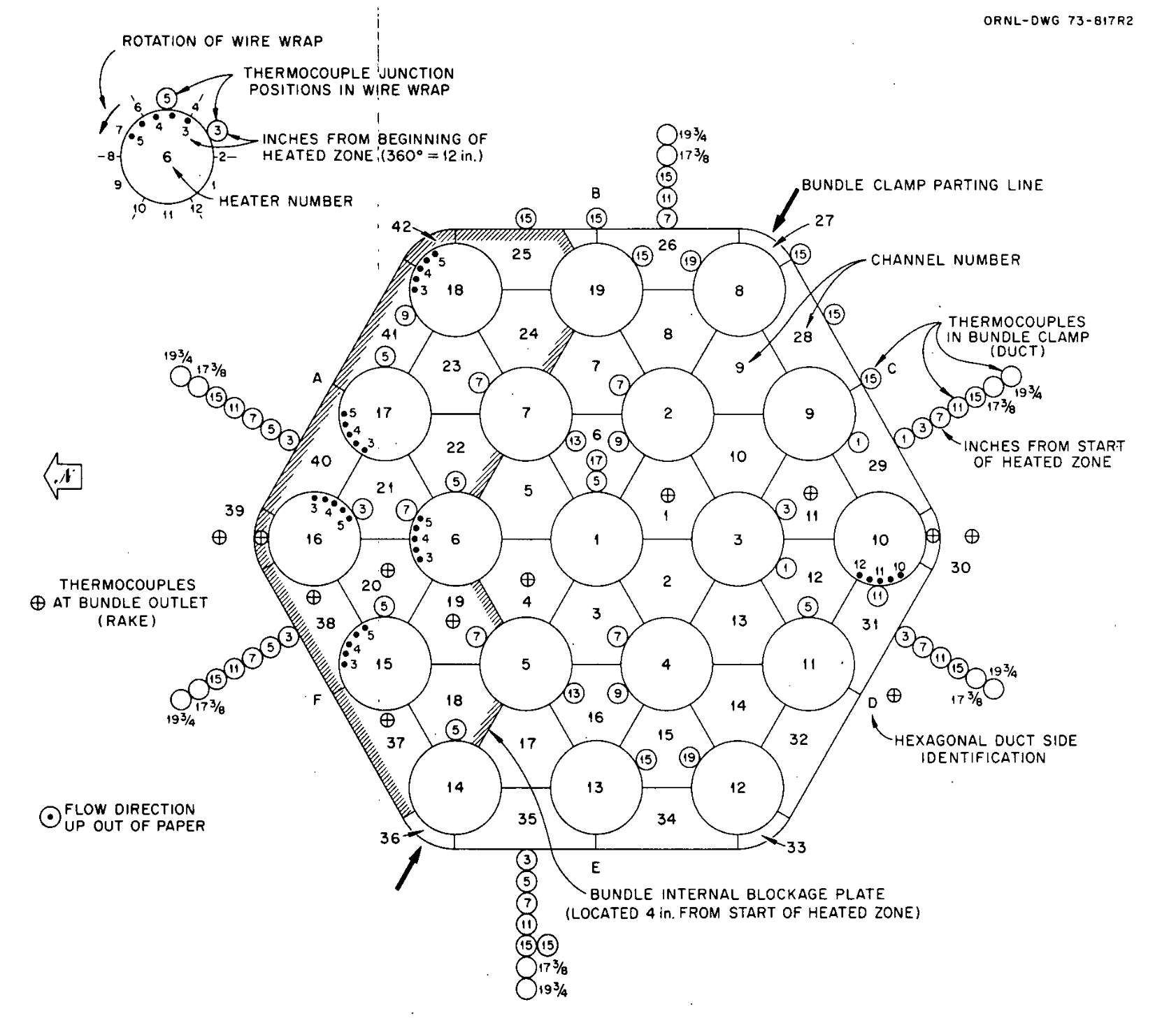
Figure 2: THORS bundle 5B cross section.
Table 1: Design and operational parameters for THORS 14-channel edge blockage benchmark.
| Experiment Parameter (unit) | Value |
|---|---|
| Number of pins (—) | |
| Rod pitch (cm) | |
| Rod diameter (cm) | |
| Wire wrap diameter (cm) | |
| Wire wrap axial pitch (cm) | |
| Flat-to-flat duct distance (cm) | |
| Inlet length (cm) | |
| Heated length (cm) | |
| Outlet length (cm) | |
| Blockage location (cm) | |
| Outlet pressure (Pa) | |
| Inlet temperature (K) | |
| Inlet velocity (m/s) | |
| Power profile (—) | Uniform |
| Power (kW) |
Results for edge blockage
The case presented here is the high-flow case (FFM Series 6, Test 12, Run 101). The thermocouples are located in the middle of the exit region. There is a subchannel index correspondence between Figure Figure 2 and the SCM model shown in Figure Figure 1 as follows: 34(39), 33(38), 18(20), 9(19), 3(4), 0(1), 12(11), and 25(30), where the number outside the parentheses refers to the SCM model, and the number inside the parentheses refers to the experimental convention. SCM calculations, along with the experimental measurements, are shown in Figure Figure 3. The code calculations exhibit generally good agreement with the experimental measurements. The least agreement occurs at the edge subchannels (), which is likely due to the model not accurately replicating the flow area there. SCM uses an assembly-wide constant wire diameter, while in the experimental assembly, the wires at the edge subchannels had half the diameter.
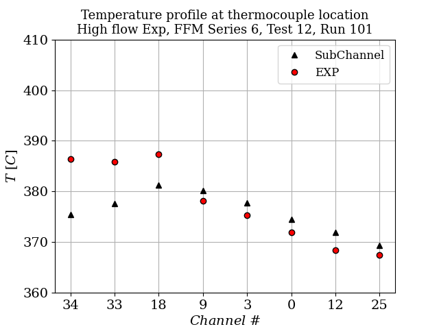
Figure 3: Exit temperature profile for high flow case ().
The second case presented here is the low flow case (FFM Series 6, Test 12, Run 109). The thermocouples are located at the middle of the exit region, same as before. SCM calculation along with the experimental measurements is shown in Figure Figure 4. The code calculations exhibits good agreement with the experimental measurements with the worst result being for the outer subchannels.
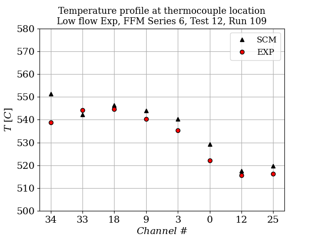
Figure 4: Exit temperature profile for low flow case ().
Subchannel Input
The input file to run the edge blockage case is presented below:
################################################################################
## THORS bundle 5B partial edge blockage benchmark                            ##
## SCM simulation, low flow case                                              ##
## POC : Vasileios Kyriakopoulos, [email protected]             ##
################################################################################
# Details on the experimental facility modeled can be found at:
# Han, J. T. "Blockages in LMFBR fuel assemblies: A review of experimental and theoretical studies." (1977).
# This input file models a block next to the duct of  the of the assembly
# 102 mm above the start of the heated section.

# Boundary conditions
T_in = 541.55 #K, low flow case
A12 = 1.00423e3
A13 = -0.21390
A14 = -1.1046e-5
rho = '${fparse A12 + A13 * T_in + A14 * T_in * T_in}'
inlet_vel = 0.48 #m/sec, low flow case
mass_flux_in = '${fparse rho *  inlet_vel}'
P_out = 2.0e5 # Pa
[TriSubChannelMesh]
  [subchannel]
    type = SCMTriSubChannelMeshGenerator
    nrings = 3
    n_cells = 50
    flat_to_flat = 0.0324290
    heated_length = 0.4572
    unheated_length_entry = 0.4064
    unheated_length_exit = 0.1524
    pin_diameter = 0.005842
    pitch = 7.2644e-3
    dwire = 0.0014224
    hwire = 0.3048
    z_blockage = '0.49 0.52'
    index_blockage = '29 31 30 32 34 33 35 15 16 8 17 18 9 19'
    reduction_blockage = '0.08 0.08 0.08 0.08 0.08 0.08 0.08 0.08 0.08 0.08 0.08 0.08 0.08 0.08'
    k_blockage = '4 4 4 4 4 4 4 4 4 4 4 4 4 4 '
  []
[]

[FluidProperties]
  [sodium]
    type = PBSodiumFluidProperties
  []
[]

[SubChannel]
  type = TriSubChannel1PhaseProblem
  fp = sodium
  n_blocks = 1
  P_out = 2.0e5
  CT = 2
  compute_density = true
  compute_viscosity = true
  compute_power = true
  P_tol = 1.0e-4
  T_tol = 1.0e-4
  implicit = true
  segregated = false
  verbose_subchannel = true
  interpolation_scheme = exponential
[]

[ICs]
  [S_IC]
    type = SCMTriFlowAreaIC
    variable = S
  []

  [w_perim_IC]
    type = SCMTriWettedPerimIC
    variable = w_perim
  []

  [T_ic]
    type = ConstantIC
    variable = T
    value = ${T_in}
  []

  [P_ic]
    type = ConstantIC
    variable = P
    value = 0.0
  []

  [DP_ic]
    type = ConstantIC
    variable = DP
    value = 0.0
  []

  [Viscosity_ic]
    type = ViscosityIC
    variable = mu
    p = ${P_out}
    T = T
    fp = sodium
  []

  [rho_ic]
    type = RhoFromPressureTemperatureIC
    variable = rho
    p = ${P_out}
    T = T
    fp = sodium
  []

  [h_ic]
    type = SpecificEnthalpyFromPressureTemperatureIC
    variable = h
    p = ${P_out}
    T = T
    fp = sodium
  []

  [mdot_ic]
    type = ConstantIC
    variable = mdot
    value = 0.0
  []
[]

[AuxKernels]
  [T_in_bc]
    type = ConstantAux
    variable = T
    boundary = inlet
    value = ${T_in}
    execute_on = 'timestep_begin'
  []
  [mdot_in_bc]
    type = SCMMassFlowRateAux
    variable = mdot
    boundary = inlet
    area = S
    mass_flux = ${mass_flux_in}
    execute_on = 'timestep_begin'
  []
  [q_prime_Aux]
    type = SCMTriPowerAux
    variable = q_prime
    power = 52800 #W, low flow case
    filename = "pin_power_profile_19.txt"
    execute_on = 'initial timestep_begin'
  []
[]

[Outputs]
  exodus = true
  csv = true
[]

[Postprocessors]
  [1]
    type = SubChannelPointValue
    variable = T
    index = 34
    execute_on = 'initial timestep_end'
    height = 0.94
  []
  [2]
    type = SubChannelPointValue
    variable = T
    index = 33
    execute_on = 'initial timestep_end'
    height = 0.94
  []
  [3]
    type = SubChannelPointValue
    variable = T
    index = 18
    execute_on = 'initial timestep_end'
    height = 0.94
  []
  [4]
    type = SubChannelPointValue
    variable = T
    index = 9
    execute_on = 'initial timestep_end'
    height = 0.94
  []
  [5]
    type = SubChannelPointValue
    variable = T
    index = 3
    execute_on = 'initial timestep_end'
    height = 0.94
  []
  [6]
    type = SubChannelPointValue
    variable = T
    index = 0
    execute_on = 'initial timestep_end'
    height = 0.94
  []
  [7]
    type = SubChannelPointValue
    variable = T
    index = 12
    execute_on = 'initial timestep_end'
    height = 0.94
  []
  [8]
    type = SubChannelPointValue
    variable = T
    index = 25
    execute_on = 'initial timestep_end'
    height = 0.94
  []
[]

[Executioner]
  type = Steady
[]

################################################################################
[MultiApps]
################################################################################
#### A multiapp that projects the solution to a detailed mesh for visualization purposes
################################################################################
  [viz]
    type = FullSolveMultiApp
    input_files = 'FFM-5B_viz.i'
    execute_on = 'FINAL'
  []
[]

[Transfers]
  [subchannel_transfer]
    type = SCMSolutionTransfer
    to_multi_app = viz
    variable = 'mdot SumWij P DP h T rho mu S w_perim'
  []
[]
Running the simulation
SCM is a MOOSE module. The user can run the input files by compiling their copy of SCM in MOOSE. `
References
- MH Fontana, TS Kress, TS Parsly, DG Thomas, and JL Wantland.
Effect of partial blockages in simulated lmfbr fuel assemblies.
Technical Report, Oak Ridge National Lab.(ORNL), Oak Ridge, TN (United States), 1973.[BibTeX]
- JT Han.
Blockages in lmfbr fuel assemblies: a review of experimental and theoretical studies.
Technical Report, Oak Ridge National Lab.(ORNL), Oak Ridge, TN (United States), 1977.[BibTeX]
- Hae-Yong Jeong, Kwi-Seok Ha, Won-Pyo Chang, Young-Min Kwon, and Yong-Bum Lee.
Modeling of flow blockage in a liquid metal-cooled reactor subassembly with a subchannel analysis code.
Nuclear technology, 149(1):71–87, 2005.[BibTeX]