EBR-II, SHRT-17 Subchannel model Validation
Contact: Vasileios Kyriakopoulos, vasileios.kyriakopoulos.at.inl.gov
Model link: EBR-II SHRT Subchannel Model
Test Description
On April 3, 1986, two tests were carried out to demonstrate the effectiveness of the negative feedback and passive cooling in the EBR-II reactor. Both tests began from full reactor power and were initiated when both the primary coolant pumps and the intermediate loop pump were simultaneously tripped, to simulate a loss-of-flow accident. SHRT-17 was a protected loss-of-flow (LOF) test and SHRT-45R was an unprotected loss-of-flow (ULOF) test. At the beginning of test SHRT-17, the primary pumps were tripped at the same time than a full control rod insertion. SHRT-45R, was similar to SHRT-17 except that during this test the plant protection system (PPS) was disabled, to prevent it from initiating a control rod scram. In the second test, SHRT-45R, the reactor power decreased due to reactivity feedback effects alone.
The EBR-II reactor vessel grid plenum sub-assembly accommodated 637 hexagonal sub-assemblies, which were installed in one of three regions: a central core, inner blanket, or outer blanket. The central core comprised the 61 sub-assemblies in the first five rows. SCM results are compared with data measured in the XX09 instrumented sub-assembly. More particularly, the code calculations are compared against temperature profile measurements in various axial elevations and the transient temperature evolution of the peak temperature in the central subchannel.
Plant Overview
Argonne National Laboratory-West’s (currently known as Idaho National Laboratory or INL) Experimental Breeder Reactor II (EBR-II) was a liquid metal reactor with a sodium-bonded metallic fuel core. EBR-II was rated for a thermal power of 62.5 MW with an electric output of approximately 20 MW. A schematic of the reactor and the primary sodium flow paths are shown in Figure 1. All major primary system components were submerged in the primary tank, which contained approximately of liquid sodium at . Two primary pumps inside this pool provided sodium to the two inlet plena of the core. Sub-assemblies in the inner core received sodium from the high-pressure inlet plenum, accounting for approximately of the total primary flow. The blanket and reflector sub-assemblies in the outer blanket region received sodium from the low-pressure inlet plenum. Hot sodium exited the sub-assemblies into a common upper plenum, where it mixed before passing into the intermediate heat exchanger (IHX).
](../../../media/subchannel/EBR-II/EBR-II_primary_tank.png)
Figure 1: Schematic of the EBR-II reactor Michelbacher et al. (2002)
The reactor-vessel grid-plenum sub-assembly accommodated 637 hexagonal sub-assemblies. The sub-assemblies were divided into three regions: core, inner blanket (IB) and outer blanket (OB). The central core comprised the 61 sub-assemblies in the first five rows. Two positions in row 3 contained safety-rod sub-assemblies and eight positions in Row 5 contained control-rod sub-assemblies. Two positions in Row 5 contained the instrumented sub-assemblies (INSAT) XX09 and XX10, and one position in Row 5 contained the in-core instrument test facility (INCOT) XY16. The remainder of the central core region contained driver fuel or experimental-irradiation sub-assemblies. EBR-II was heavily instrumented to measure mass flow rates, temperatures, and pressures, throughout the system.
SCM results are compared with data measured in the XX09 instrumented sub-assembly. More particularly, the code calculations are compared against temperature profile measurements in various axial elevations and the transient temperature evolution of the peak temperature in the central subchannel.
Instrumented sub-assemblies
The SHRT-17 test is a protected LOF test. This test was initiated by a trip of the primary and intermediate pumps under the rated-power of 57.3MW. The reactor was scrammed at the same time as the pump trips. As flow dissipated in the primary system after the pump trips, cooling of the core transitions from forced to natural circulation, while temperature and flow rate converge to an equilibrium state.
The SHRT-45R test is an unprotected LOF test. Similarly to SHRT-17, this test was initiated by a trip of the primary and intermediate pumps under the rated-power of 60.0 MW, but without scram. In the SHRT-45R experiment, the auxiliary electromagnetic pump (EMP) was kept operational throughout the test duration. As a result, the cooling situation is not fully natural convection, but since the EMP flow rate is very low, it is also not fully forced circulation. Because of the operation of the EMP in the SHRT-45R experiment, the coolant mass flow rate converges to about two times that in the SHRT-17 experiment.
Both tests run for seconds.
This work utilizes data measured by the instrumented sub-assembly XX09. XX09 was a fueled sub-assembly specifically designed with a variety of instrumentation to provide data for benchmark validation purposes. The standard-type fueled sub-assembly contains 91 fuel pins, whereas in XX09 the outer row of fuel pins was removed and a guide thimble was inserted instead, as shown in Figure 2, Figure 3.
](../../../media/subchannel/EBR-II/XX09.png)
Figure 2: XX09 Instrumented sub-assembly axial-section Sumner and Wei (2012)
](../../../media/subchannel/EBR-II/XX09_3.png)
Figure 3: XX09 Instrumented sub-assembly cross-section Sumner and Wei (2012)
Boundary conditions
The values for the inlet mass flow rate, power, and inlet coolant temperature are specified in the EBR-II SHRT benchmark Sumner and Wei (2012). The value of outlet pressure has been approximated based on the operation conditions of the EBR-II before the transients. These values represent the steady state conditions leading to the transients.
| Experimental steady-state parameters |
|---|
| Experiment Parameter (Unit) | SHRT-17 | SHRT-45R |
|---|---|---|
| Inlet Mass flow rate of XX09 (kg/s) | 2.45 | 2.427 |
| Power of XX09 (kW) | 486.2 | 379.8 |
| Inlet coolant temperature (K) | 624.7 | 616.4 |
| Outlet Pressure (kPa) | 200.0 | 200.0 |
During the SHRT transients, the mass flow rate and power vary. The normalized power and mass flow rate during the transients have been adapted from Mochizuki et al. (2014) , Mochizuki and Muranaka (2018) and are presented in Figure 4. This information is used as input for the SCM transient calculations. The work in the cited sources utilizes a NETFLOW++ Mochizuki (2010) simulation to inform a COBRA-IV-I Wheeler et al. (1976) model of the instrumented sub-assembly XX09. It should be noted that for SHRT-17, the power generation throughout the transient is solely due to decay heat because the protection system shuts down the reactor. For the SHRT-45R test, fission power continues into the transient for some time until the reactivity feedback mechanisms ultimately shut down the reactor.
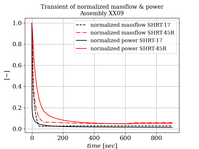
Figure 4: Transient boundary conditions
Improvements
The subchannel module SCM (formely known as Pronghorn-SC) results, were improved by two successive off-line corrections. The first correction involved calculating a more realistic radial and axial pin power profile, using a Serpent-2 simulation of the EBR-II core. The second correction involved calculating the heat flux from the edge subchannels to the inner duct of the thimble, using a Pronghorn-FV simulation and applying this heat flux in the SCM simulations. This presentation doesn't include the Pronghorn correction and focuses only on open source codes results (SCM standalone calculations). Further information can be found in Tano et al. (2024).
Steady State Results
Three simulation results are compared against the experimental measurements of thermocouples at the outlet of the heated section (TTC):
Results from the DASSH Atz et al. (2021),subchannel code, which is used as a reference for verification.
Results from SCM with a uniform (axially and radially) pin power profile.
Results from SCM only with the corrected power profile computed via the Serpent-2 model.
The DASSH subchannel code models the internal pin region of sub-assembly XX09 and the thimble region. The standalone SCM simulation only models the internal pin region. Both codes don't consider the neighboring sub-assemblies.
Figure 5, Figure 6 present the results for the steady-state radial temperature profiles calculated at position TTC, which is near the outlet of the fueled section, for tests SHRT-17 and SHRT-45R, respectively. The figures include calculations obtained from the DASSH subchannel code. DASSH solves for the conservation of axial momentum and energy and assumes that the cross flows are produced to close the mass balance, i.e., there is no explicit equation solved for the conservation of lateral momentum in the code, and advective radial heat transfer due to cross flows is ignored. Radial thermal mixing is modeled by being lumped into the conduction term and approximated by enhancing the thermal diffusivity with an eddy diffusivity obtained from correlation Atz et al. (2021). This approximation is generally accurate for liquid-metal-cooled reactors, and hence DASSH results are used as a baseline for the performance of the subchannel code.
For SHRT-17, in the uniform pin power case, both SCM and DASSH exhibit similar behavior. Since DASSH does not resolve the crossflows (contrary to SCM), similar results indicate that crossflows might not be instrumental, in determining the temperature profile for this problem. Additionally, DASSH predicts a slightly less skewed distribution than SCM, which is closer to the experimental results. This means that the crossflows may be underestimated by the lateral momentum balance equation solved by SCM, or that the thimble model incorporated in DASSH improves accuracy. Nonetheless, both the SCM and DASSH calculations, are close enough to suggest that those differences in modeling approach, do not produce large discrepancies in the results.
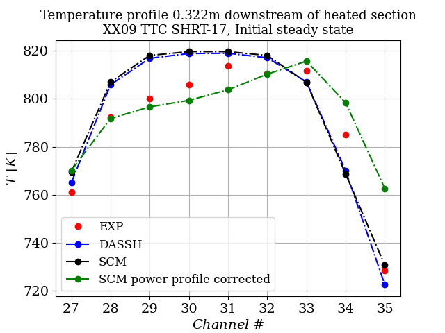
Figure 5: Temperature profile at the start of Test SHRT-17
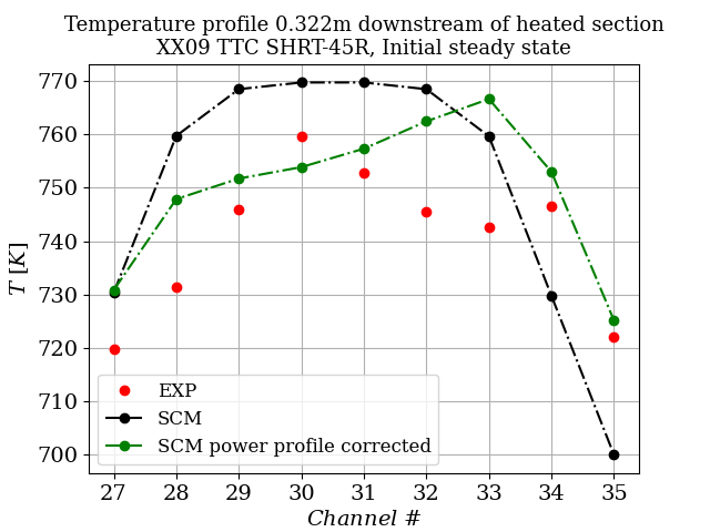
Figure 6: Temperature profile at the start of Test SHRT-45R
Transient Results
Simulations with uniform power profile are performed with the SCM model. Results are compared against experimental measurements and the NETFLOW++/COBRA simulations are used as a reference result. The temperature transient calculations, together with the experimental measurements at thermocouple location TTC-31, are presented in Figure 7,Figure 8. In SHRT-17, the power of the XX09 sub-assembly decreases rapidly at time zero due to the reactor scram, which results in a sudden coolant temperature decrease. On the other hand, in SHRT-45R there is no scram of the reactor, so power decreases at a much lower pace. This is why no sudden temperature drop is observed at time zero.
Then for both tests, the flow rate gradually decreases due to the pump trip and coasts-down, causing the coolant temperature to increase to a peak of around for SHRT-17 and for SHRT-45R. Following that, the coolant temperature decreases and levels off to for SHRT-17 and for SHRT-45R with the establishment of natural circulation due to decay heat and buoyancy effects.
For both SHRT-17 and SHRT-45R, the stand-alone SCM calculated transient, underestimates the measured result of the peak temperature, by approximately . The thermal inertia of the solid structures play an important role in determining the temperature field transient, towards the establishment of natural convection. As these structures are not modeled in the SCM simulations, a more rapid decrease in the temperature field is observed in the computed cases. Nonetheless, the thermal inertia of these structures does not play a fundamental role once natural convection is established, as the system is in thermal equilibrium. Hence, better agreement is obtained for this part of the transient. In general, good results are obtained for both transients, with the SCM being in better agreement with the experiment compared to the NETFLOW++/COBRA simulations.
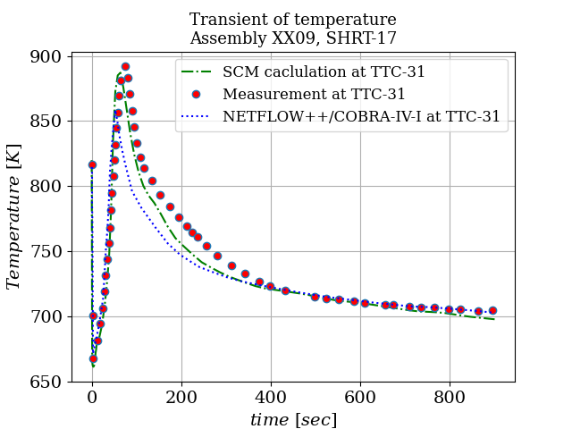
Figure 7: Transient Test SHRT-17
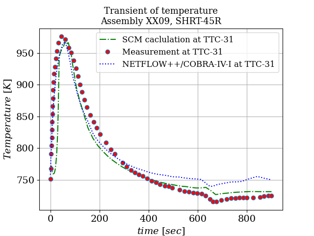
Figure 8: Transient Test SHRT-45R
Input files
To run the steady state problems use the following input files:
# Following Benchmark Specifications and Data Requirements for EBR-II Shutdown Heat Removal Tests SHRT-17 and SHRT-45R
# Available at: https://publications.anl.gov/anlpubs/2012/06/73647.pdf
###################################################
# Steady state subchannel calculation
# Thermal-hydraulics parameters
###################################################
T_in = 624.70556 #Kelvin
Total_Surface_Area = 0.000854322 #m2
Mass_In = 2.45 #kg/sec
mass_flux_in = '${fparse Mass_In / Total_Surface_Area}' #kg/m2
P_out = 2.0e5 #Pa
Power_initial = 486200 #W (Page 26,35 of ANL document)
###################################################
# Geometric parameters
###################################################
scale_factor = 0.01
fuel_pin_pitch = '${fparse 0.5664*scale_factor}'
fuel_pin_diameter = '${fparse 0.4419*scale_factor}'
wire_z_spacing = '${fparse 15.24*scale_factor}'
wire_diameter = '${fparse 0.1244*scale_factor}'
inner_duct_in = '${fparse 4.64*scale_factor}'
n_rings = 5
heated_length = '${fparse 34.3*scale_factor}'
unheated_length_exit = '${fparse 26.9*scale_factor}'
###################################################

[TriSubChannelMesh]
  [subchannel]
    type = SCMTriSubChannelMeshGenerator
    nrings = ${n_rings}
    n_cells = 50
    flat_to_flat = ${inner_duct_in}
    unheated_length_exit = ${unheated_length_exit}
    heated_length = ${heated_length}
    pin_diameter = ${fuel_pin_diameter}
    pitch = ${fuel_pin_pitch}
    dwire = ${wire_diameter}
    hwire = ${wire_z_spacing}
  []

  [fuel_pins]
    type = SCMTriPinMeshGenerator
    input = subchannel
    nrings = ${n_rings}
    n_cells = 50
    unheated_length_exit = ${unheated_length_exit}
    heated_length = ${heated_length}
    pitch = ${fuel_pin_pitch}
  []

  [duct]
    type = SCMTriDuctMeshGenerator
    input = fuel_pins
    nrings = ${n_rings}
    n_cells = 50
    flat_to_flat = ${inner_duct_in}
    unheated_length_exit = ${unheated_length_exit}
    heated_length = ${heated_length}
    pitch = ${fuel_pin_pitch}
  []
[]

[Functions]
  [axial_heat_rate]
    type = ParsedFunction
    value = '(pi/2)*sin(pi*z/L)*exp(-alpha*z)/(1.0/alpha*(1.0 - exp(-alpha*L)))*L'
    vars = 'L alpha'
    vals = '${heated_length} 1.8012'
  []
[]

[AuxVariables]
  [mdot]
    block = subchannel
  []
  [SumWij]
    block = subchannel
  []
  [P]
    block = subchannel
  []
  [DP]
    block = subchannel
  []
  [h]
    block = subchannel
  []
  [T]
    block = subchannel
  []
  [rho]
    block = subchannel
  []
  [S]
    block = subchannel
  []
  [w_perim]
    block = subchannel
  []
  [mu]
    block = subchannel
  []
  [displacement]
    block = subchannel
  []
  [q_prime]
    block = fuel_pins
  []
  [Tpin]
    block = fuel_pins
  []
  [Dpin]
    block = fuel_pins
  []
  [q_prime_duct]
    block = duct
  []
  [Tduct]
    block = duct
  []
[]

[FluidProperties]
  [sodium]
    type = PBSodiumFluidProperties
  []
[]

[SubChannel]
  type = TriSubChannel1PhaseProblem
  fp = sodium
  n_blocks = 1
  P_out = ${P_out}
  CT = 2.6
  compute_density = true
  compute_viscosity = true
  compute_power = true
  P_tol = 1.0e-4
  T_tol = 1.0e-5
  implicit = true
  segregated = false
  interpolation_scheme = 'upwind'
  verbose_subchannel = true
[]

[ICs]
  [S_IC]
    type = SCMTriFlowAreaIC
    variable = S
  []

  [w_perim_IC]
    type = SCMTriWettedPerimIC
    variable = w_perim
  []

  [q_prime_IC]
    type = SCMTriPowerIC
    variable = q_prime
    power = ${Power_initial}
    filename = "pin_power_profile61_uniform.txt"
    axial_heat_rate = axial_heat_rate
  []

  [T_ic]
    type = ConstantIC
    variable = T
    value = ${T_in}
  []

  [Dpin_ic]
    type = ConstantIC
    variable = Dpin
    value = ${fuel_pin_diameter}
  []

  [P_ic]
    type = ConstantIC
    variable = P
    value = 0.0
  []

  [DP_ic]
    type = ConstantIC
    variable = DP
    value = 0.0
  []

  [Viscosity_ic]
    type = ViscosityIC
    variable = mu
    p = ${P_out}
    T = T
    fp = sodium
  []

  [rho_ic]
    type = RhoFromPressureTemperatureIC
    variable = rho
    p = ${P_out}
    T = T
    fp = sodium
  []

  [h_ic]
    type = SpecificEnthalpyFromPressureTemperatureIC
    variable = h
    p = ${P_out}
    T = T
    fp = sodium
  []

  [mdot_ic]
    type = ConstantIC
    variable = mdot
    value = 0.0
  []
[]

[AuxKernels]
  [T_in_bc]
    type = ConstantAux
    variable = T
    boundary = inlet
    value = ${T_in}
    execute_on = 'timestep_begin'
    block = subchannel
  []
  [mdot_in_bc]
    type = SCMMassFlowRateAux
    variable = mdot
    boundary = inlet
    area = S
    mass_flux = ${mass_flux_in}
    execute_on = 'timestep_begin'
  []
[]

[Outputs]
  csv = true
[]

!include XX09_output.i

[Executioner]
  type = Steady
[]

################################################################################
# A multiapp that projects data to a detailed mesh
################################################################################
[MultiApps]
  [viz]
    type = FullSolveMultiApp
    input_files = '3d_SCM_SS.i'
    execute_on = 'FINAL'
  []
[]

[Transfers]
  [subchannel_transfer]
    type = SCMSolutionTransfer
    to_multi_app = viz
    variable = 'mdot SumWij P DP h T rho mu S'
  []
  [pin_transfer]
    type = SCMPinSolutionTransfer
    to_multi_app = viz
    variable = 'Tpin q_prime'
  []
[]
To run the transient problems use the following input files:
# Following Benchmark Specifications and Data Requirements for EBR-II Shutdown Heat Removal Tests SHRT-17 and SHRT-45R
# Available at: https://publications.anl.gov/anlpubs/2012/06/73647.pdf
# Transient Subchannel calculation
###################################################
# Thermal-hydraulics parameters
###################################################
T_in = 624.7 #Kelvin
Total_Surface_Area = 0.000854322 #m3
mass_flux_in = '${fparse 2.45 / Total_Surface_Area}'
P_out = 2.0e5
Power_initial = 486200 #W (Page 26,35 of ANL document)
###################################################
# Geometric parameters
###################################################
scale_factor = 0.01
fuel_pin_pitch = '${fparse 0.5664*scale_factor}'
fuel_pin_diameter = '${fparse 0.4419*scale_factor}'
wire_z_spacing = '${fparse 15.24*scale_factor}'
wire_diameter = '${fparse 0.1244*scale_factor}'
inner_duct_in = '${fparse 4.64*scale_factor}'
n_rings = 5
heated_length = '${fparse 34.3*scale_factor}'
unheated_length_exit = '${fparse 26.9*scale_factor}'
###################################################

[TriSubChannelMesh]
  [subchannel]
    type = SCMTriSubChannelMeshGenerator
    nrings = ${n_rings}
    n_cells = 50
    flat_to_flat = ${inner_duct_in}
    unheated_length_exit = ${unheated_length_exit}
    heated_length = ${heated_length}
    pin_diameter = ${fuel_pin_diameter}
    pitch = ${fuel_pin_pitch}
    dwire = ${wire_diameter}
    hwire = ${wire_z_spacing}
    spacer_z = '0.0'
    spacer_k = '0.0'
  []

  [fuel_pins]
    type = SCMTriPinMeshGenerator
    input = subchannel
    nrings = ${n_rings}
    n_cells = 50
    unheated_length_exit = ${unheated_length_exit}
    heated_length = ${heated_length}
    pitch = ${fuel_pin_pitch}
  []
[]

[AuxVariables]
  [mdot]
    block = subchannel
  []
  [SumWij]
    block = subchannel
  []
  [P]
    block = subchannel
  []
  [DP]
    block = subchannel
  []
  [h]
    block = subchannel
  []
  [T]
    block = subchannel
  []
  [rho]
    block = subchannel
  []
  [S]
    block = subchannel
  []
  [w_perim]
    block = subchannel
  []
  [mu]
    block = subchannel
  []
  [q_prime_init]
    block = fuel_pins
  []
  [power_history_field]
    block = fuel_pins
  []
  [q_prime]
    block = fuel_pins
  []
  [Tpin]
    block = fuel_pins
  []
  [Dpin]
    block = fuel_pins
  []
  [displacement]
    block = subchannel
  []
[]

[FluidProperties]
  [sodium]
    type = PBSodiumFluidProperties
  []
[]

[SubChannel]
  type = TriSubChannel1PhaseProblem
  fp = sodium
  n_blocks = 1
  P_out = ${P_out}
  CT = 2.6
  compute_density = true
  compute_viscosity = true
  compute_power = true
  P_tol = 1.0e-4
  T_tol = 1.0e-4
  implicit = true
  segregated = false
  interpolation_scheme = 'upwind'
[]

[ICs]
  [S_IC]
    type = SCMTriFlowAreaIC
    variable = S
  []

  [w_perim_IC]
    type = SCMTriWettedPerimIC
    variable = w_perim
  []

  [q_prime_IC]
    type = SCMTriPowerIC
    variable = q_prime_init
    power = ${Power_initial}
    filename = "pin_power_profile61_uniform.txt"
  []

  [T_ic]
    type = ConstantIC
    variable = T
    value = ${T_in}
  []

  [Dpin_ic]
    type = ConstantIC
    variable = Dpin
    value = ${fuel_pin_diameter}
  []

  [P_ic]
    type = ConstantIC
    variable = P
    value = 0.0
  []

  [DP_ic]
    type = ConstantIC
    variable = DP
    value = 0.0
  []

  [Viscosity_ic]
    type = ViscosityIC
    variable = mu
    p = ${P_out}
    T = T
    fp = sodium
  []

  [rho_ic]
    type = RhoFromPressureTemperatureIC
    variable = rho
    p = ${P_out}
    T = T
    fp = sodium
  []

  [h_ic]
    type = SpecificEnthalpyFromPressureTemperatureIC
    variable = h
    p = ${P_out}
    T = T
    fp = sodium
  []

  [mdot_ic]
    type = ConstantIC
    variable = mdot
    value = 0.0
  []
[]

[Functions]
  [power_func]
    type = PiecewiseLinear
    data_file = 'power_history_SHRT17.csv'
    format = "columns"
    scale_factor = 1.0
  []
  [mass_flux_in]
    type = PiecewiseLinear
    data_file = 'massflow_SHRT17.csv'
    format = "columns"
    scale_factor = '${fparse mass_flux_in / 2.45}'
  []

  [time_step_limiting]
    type = PiecewiseLinear
    xy_data = '0.1 0.1
               10.0 10.0'
  []
[]

[Controls]
  [mass_flux_ctrl]
    type = RealFunctionControl
    parameter = 'Postprocessors/mass_flux_PP/value'
    function = 'mass_flux_in'
    execute_on = 'initial timestep_begin'
  []
[]

[AuxKernels]
  [T_in_bc]
    type = ConstantAux
    variable = T
    boundary = inlet
    value = ${T_in}
    execute_on = 'timestep_begin'
    block = subchannel
  []
  [mdot_in_bc]
    type = SCMMassFlowRateAux
    variable = mdot
    boundary = inlet
    area = S
    mass_flux = mass_flux_PP
    execute_on = 'timestep_begin'
  []
  [populate_power_history]
    type = FunctionAux
    variable = power_history_field
    function = 'power_func'
    execute_on = 'INITIAL TIMESTEP_BEGIN'
  []
  [change_q_prime]
    type = ParsedAux
    variable = q_prime
    args = 'q_prime_init power_history_field'
    function = 'q_prime_init*power_history_field'
    execute_on = 'INITIAL TIMESTEP_BEGIN'
  []
[]

[Outputs]
  csv = true
[]

[Postprocessors]
  [report_pressure_outlet]
    type = Receiver
    default = ${P_out}
  []

  [TTC-31]
    type = SubChannelPointValue
    variable = T
    index = 0
    execute_on = 'initial timestep_end'
    height = 0.322
  []

  [post_func]
    type = ElementIntegralVariablePostprocessor
    block = fuel_pins
    variable = q_prime
    execute_on = 'INITIAL TIMESTEP_BEGIN'
  []

  [mass_flux_PP]
    type = ConstantPostprocessor
    value = ${mass_flux_in}
  []

  [mass_flow_PP]
    type = ParsedPostprocessor
    expression = '${Total_Surface_Area} * mass_flux_PP'
    pp_names = 'mass_flux_PP'
  []
[]

[Executioner]
  type = Transient

  start_time = -1.0
  end_time = 900.0
  [TimeStepper]
    type = IterationAdaptiveDT
    dt = 0.1
    iteration_window = 5
    optimal_iterations = 6
    growth_factor = 1.1
    cutback_factor = 0.8
    timestep_limiting_function = 'time_step_limiting'
  []
  dtmax = 20
[]

################################################################################
# A multiapp that projects data to a detailed mesh
################################################################################
[MultiApps]
  [viz]
    type = TransientMultiApp
    input_files = '3d_SCM_TR.i'
    execute_on = 'INITIAL TIMESTEP_END'
    catch_up = true
  []
[]

[Transfers]
  [subchannel_transfer]
    type = SCMSolutionTransfer
    to_multi_app = viz
    variable = 'mdot SumWij P DP h T rho mu S'
  []
  [pin_transfer]
    type = SCMPinSolutionTransfer
    to_multi_app = viz
    variable = 'Tpin q_prime'
  []
[]The corrected power profile is read by the following .txt file (pin_power_profile61.txt):
0.8477457157073588
0.8438703828994463
0.8645320077724137
0.8753092523824995
0.8645320077724137
0.8438703828994463
0.8339698482446043
0.8369432200392273
0.8566725635473428
0.8786532264515594
0.8892530859209314
0.9013443399053171
0.8892530859166047
0.8786532264515594
0.856672563539393
0.8369432200392273
0.8267424533965094
0.8177938527394076
0.8267424534001606
0.8272594696733904
0.8472934986320385
0.8681632858448316
0.8898769072293857
0.9017653027695607
0.9136133010186879
0.9253977864165255
0.9136133010118554
0.9017653027628166
0.8898769072293858
0.8681632858325796
0.8472934986203717
0.8272594696733904
0.8181228874882326
0.8089377252083733
0.7997220243775588
0.8089377252136014
0.8181228874935296
1.1303279098639667
1.1711970176131872
1.212446682465516
1.25429938376924
1.2960890595043835
1.3230893402868509
1.3483812226578455
1.3722914884147328
1.3941161594994989
1.3722914883971098
1.3483812226390315
1.3230893402669708
1.2960890595043835
1.2542993837371461
1.2124466824337514
1.1711970175818887
1.1303279098639671
1.1147644628376598
1.097730853264873
1.0797248303470215
1.0605178830397783
1.0797248303611697
1.0977308532782715
1.1147644628502191
The uniform power profile is read by the following .txt file (pin_power_profile61_uniform.txt):
1.0
1.0
1.0
1.0
1.0
1.0
1.0
1.0
1.0
1.0
1.0
1.0
1.0
1.0
1.0
1.0
1.0
1.0
1.0
1.0
1.0
1.0
1.0
1.0
1.0
1.0
1.0
1.0
1.0
1.0
1.0
1.0
1.0
1.0
1.0
1.0
1.0
1.0
1.0
1.0
1.0
1.0
1.0
1.0
1.0
1.0
1.0
1.0
1.0
1.0
1.0
1.0
1.0
1.0
1.0
1.0
1.0
1.0
1.0
1.0
1.0
The Functions block defines the shape of the axial power profile:
[Functions]
  [axial_heat_rate]
    type = ParsedFunction
    value = '(pi/2)*sin(pi*z/L)*exp(-alpha*z)/(1.0/alpha*(1.0 - exp(-alpha*L)))*L'
    vars = 'L alpha'
    vals = '${heated_length} 1.8012'
  []
[]Transient BC's
For the transient case the user needs to provide transient boundary conditions:
First define the initial power and the power history field along with the default variable q_prime, in the AuxVariables block
  [q_prime_init]
    block = fuel_pins
  []
  [power_history_field]
    block = fuel_pins
  []
  [q_prime]
    block = fuel_pins
  []
Then, define the transient evolution of the boundary conditions in the Functions block based on .csv files:
[Functions]
  [power_func]
    type = PiecewiseLinear
    data_file = 'power_history_SHRT17.csv'
    format = "columns"
    scale_factor = 1.0
  []
  [mass_flux_in]
    type = PiecewiseLinear
    data_file = 'massflow_SHRT17.csv'
    format = "columns"
    scale_factor = '${fparse mass_flux_in / 2.45}'
  []

  [time_step_limiting]
    type = PiecewiseLinear
    xy_data = '0.1 0.1
               10.0 10.0'
  []
[]The functions defined above are given normalized and they multiply the initial steady state conditions:
[Controls]
  [mass_flux_ctrl]
    type = RealFunctionControl
    parameter = 'Postprocessors/mass_flux_PP/value'
    function = 'mass_flux_in'
    execute_on = 'initial timestep_begin'
  []
[][AuxKernels]
[T_in_bc]
type = ConstantAux
variable = T
boundary = inlet
value = ${T_in}
execute_on = 'timestep_begin'
block = subchannel
[]
[mdot_in_bc]
type = SCMMassFlowRateAux
variable = mdot
boundary = inlet
area = S
mass_flux = mass_flux_PP
execute_on = 'timestep_begin'
[]
[populate_power_history]
type = FunctionAux
variable = power_history_field
function = 'power_func'
execute_on = 'INITIAL TIMESTEP_BEGIN'
[]
[change_q_prime]
type = ParsedAux
variable = q_prime
args = 'q_prime_init power_history_field'
function = 'q_prime_init*power_history_field'
execute_on = 'INITIAL TIMESTEP_BEGIN'
[]
[]References
- Milos Atz, Micheal A Smith, and Florent Heidet.
Ducted assembly steady-state heat transfer software (dassh): theory manual.
Technical Report, Argonne National Lab.(ANL), Argonne, IL (United States), 2021.[BibTeX]
- J A Michelbacher, C E Baily, D K Baird, S P Henslee, C J Knight, and K E Rosenberg.
Shutdown and closure of the experimental breeder reactor - ii.
ICONE-10, 9 2002.
URL: https://www.osti.gov/biblio/801571, doi:10.1115/ICONE10-22462.[BibTeX]
- Hiroyasu Mochizuki.
Development of the plant dynamics analysis code netflow++.
Nuclear Engineering and Design, 240(3):577–587, 2010.[BibTeX]
- Hiroyasu Mochizuki and Kohmei Muranaka.
Benchmark analyses for ebr-ii shutdown heat removal tests shrt-17 and shrt-45r–(2) subchannel analysis of instrumented fuel sub-assembly.
Nuclear Engineering and Design, 330:14–27, 2018.[BibTeX]
- Hiroyasu Mochizuki, Kohmei Muranaka, Takayuki Asai, and WFG Van Rooijen.
Benchmark analyses for ebr-ii shutdown heat removal tests shrt-17 and shrt-45r.
Nuclear Engineering and Design, 275:312–321, 2014.[BibTeX]
- Tyler S Sumner and Thomas YC Wei.
Benchmark specifications and data requirements for ebr-ii shutdown heat removal tests shrt-17 and shrt-45r.
Technical Report, Argonne National Lab.(ANL), Argonne, IL (United States), 2012.[BibTeX]
- Mauricio Tano, Vasileios Kyriakopoulos, James McCay, and Tyrell Arment.
Validation of pronghorn’s subchannel code using ebr-ii shutdown heat removal tests: shrt-17 and shrt-45r.
Nuclear Engineering and Design, 416:112783, 2024.[BibTeX]
- CL Wheeler, CW Stewart, RJ Cena, DS Rowe, and AM Sutey.
Cobra-iv-i: an interim version of cobra for thermal-hydraulic analysis of rod bundle nuclear fuel elements and cores.
Technical Report, Battelle Pacific Northwest Labs., Richland, Wash.(USA), 1976.[BibTeX]