Simulation Results and Discussions
FCCI and CCCI Wastage Thickness
The FCCI wastage thickness profile of Pin DP11 predicted by BISON is compared with the corresponding experimental measurement Carmack (2012) and Pahl et al. (1993) on micrograph photos of the sectioned specimens from the four sibling irradiated fuel pins of focus. As shown in Figure 1, BISON prediction is generally consistent with the measurement data, providing a foundation for reliable prediction of cladding deformation due to fuel-cladding chemical interaction (FCCI) thinning. On the other hand, the coolant-cladding chemical interaction (CCCI) wastage formation was found to be 20 microns near the cladding outer surface elevation corresponding to the top of the fuel slug, which is also consistent with the BISON prediction.
 wastage thickness of Pin DP11 with the measured data of the same irradiated pin and its siblings.](../../media/ebr2_x447_dp11/fcci_dp11.png)
Figure 1: Comparison of the FCCI wastage thickness of Pin DP11 with the measured data of the same irradiated pin and its siblings.
Cladding Hoop Strain
For X447 pins such as Pin DP11, a major consequence of cladding thinning, mainly due to FCCI, is the degradation in cladding's mechanical strength and thus enhancement in cladding deformation caused by accumulated fission gas within the cladding. As the FCCI is only severe near the cladding inner surface corresponding to the top section of the fuel slug, the cladding deformation is also prominent in this region. As shown by the blue curves in Figure 2, the majority of the cladding only experienced minor deformation after the 10% burnup. On the other hand, near the top of the fuel slug, prominent cladding deformation up to 2.0% strain was observed. Additionally, it is worth mentioning that the measured cladding deformation value shown in Figure 2 are the circumferentially maximum values, the corresponding minimum peak value is 2.963 mm (compared to 2.977 mm) for this pin.
Unlike other fuel irradiation experiments, where the cladding stayed far away from the creep rupture domain, the cladding in X447 was observed to be subjected to breaching due to creep rupture. In that case, tertiary creep was expected to make significant contributions to the cladding deformation. In Figure 2, it is prominent that taking into account the tertiary creep, the predicted cladding deformation is more consistent with the profilometry measurement. It is noticeable that the current BISON model predicts lower cladding strain compared to the PIE measurement, which will be discussed later.
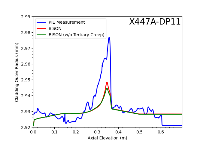
Figure 2: BISON predicted cladding deformation of Pin DP11 (with and without taking tertiary cladding creep into consideration) compared with the circumferential maximum cladding diameters measured by contact profilometry.
Fuel Axial Elongation
The use of mortar contact model enables numerically stable simulation for fuel-cladding contact with friction. Such an improvement is important to the correct prediction of non-recoverable axial fuel elongation, which is the final fuel elongation minus thermal expansion. As shown in Figure 3, the BISON fuel elongation prediction of Pin DP11, which is tightly controlled by the combined effects of the fuel anisotropic swelling factor and the fuel-clad tangential contact coefficient of friction, closely matches the Post-Irradiation Examination (PIE) measurement (i.e., gamma scan (Carmack, 2012)).
 measurement (DP11).](../../media/ebr2_x447_dp11/DP11_Axial_Growth.png)
Figure 3: BISON predicted fuel elongation compared with PIE measurement (DP11).
Fuel Failure Criteria
Under the legacy Integral Fast Reactor (IFR) program, two pin failure criteria were developed for normal operation condition based on HT9 cladding damage (Briggs et al., 1995):
Thermal component of plastic hoop strain during normal operation is less than 1%.
Cumulative Damage Fraction (CDF) during normal operation is less than 0.05.
For the first criterion, the maximum predicted cladding hoop strain value for Pin DP11 is 0.94%. Under the high cladding temperature conditions involved in the IFR X447/A Experiment, the cladding hoop strain is dominated by thermal creep. Namely, based on the BISON model, Pin DP11 has a maximum cladding hoop strain that approaches the failure criterion of 1%. While the BISON prediction provides correct trends and consistence, it is worth noting that the 1% strain criterion is conservative because the actual observed failure usually starts at ~2% hoop strain. As shown in Figure 2, current models still underestimate hoop strain a bit, as the PIE measured strain values of the pin is ~1.9%.
On the other hand, the maximum predicted CDF value of Pin DP11 is ~0.11, which exceeds the CDF failure criterion of 0.05. Again, this is consistent with the conclusion of the IFR X447/A Experiment that Pin DP11 was a sibling pin of the failed pins DP70 and DP75. When the CDF based criterion was established, a statistical relation between CDF and cladding failure probability was developed based on the long-term thermal creep rupture experiment results of unirradiated HT9 specimens (Briggs et al., 1995). Based on this correlation, the failure probability of Pin DP11 is very low. Similar underestimation in CDF was also reported in the original IFR documentation (Briggs et al., 1995) when using LIFE-METAL, which is potentially related to the limitations of the experimental data used for developing the correlation (e.g., unirradiated specimens).
Therefore, there exists an underestimate in fuel pin cladding failure based on both cladding hoop strain and CDF criteria. The potential primary sources of such discrepancies could include:
The current empirical HT9 creep model can be improved.
The local details are not covered by the adopted 2D-RZ model (e.g., preferential FCCI at some circumferential locations and thermal effects from the spacer wire).
The current FCCI based cladding degradation model is based on creep rupture, whereas it does not take the microstructural damage due to FCCI into account, such as the grain boundary attack and consequent intergranular crack initiation as reported recently (Harp et al., 2017).
These factors should be improved with the currently in-development advanced microstructure-informed creep and mechanistic FCCI models, as well as the potential 3D modeling approach.
Conclusion
This VTB single pin model, enhanced with automatic differentiation and mortar mechanical contact, demonstrates BISON's capabilities in simulating Sodium-cooled Fasted Reactor (SFR) metal fuel pins with conventional design through integration with Fuels Irradiation and Physics Database (FIPD). FCCI wastage thickness profiles and cladding hoop strain predicted by BISON are generally consistent with the experimental measurement with some limited discrepancies. With the mortar contact model, the fuel axial elongation calculation more closely resembles PIE measurements. BISON-FIPD integration is demonstrated to be a powerful tool for SFR metallic fuel model V&V.
References
- L. L. Briggs, L. K. Chang, and D. J. Hill.
Safety Analysis and Technical Basis for Establishing an Interim Burnup Limit for Mark-V and Mark-VA Fueled Subassemblies in EBR-II.
Technical Report ANL-NSE-1, Argonne National Laboratory, 1995.[BibTeX]
- William J Carmack.
Temperature and burnup correlated FCCI in U-10Zr metallic fuel.
Technical Report INL/EXT-12-25550, Idaho National Lab.(INL), Idaho Falls, ID (United States), 2012.[BibTeX]
- Jason M Harp, Douglas L Porter, Brandon D Miller, Tammy L Trowbridge, and William J Carmack.
Scanning electron microscopy examination of a fast flux test facility irradiated U-10Zr fuel cross section clad with HT-9.
Journal of Nuclear Materials, 494:227–239, 2017.[BibTeX]
- RG Pahl, CE Lahm, and SL Hayes.
Performance of HT9 clad metallic fuel at high temperature.
Journal of nuclear materials, 204:141–147, 1993.[BibTeX]