Molten Salt Reactor Experiment (MSRE) SAM Modeling
Contact: Jun Fang, fangj.at.anl.gov
Model link: Steady-State SAM Model
MSRE Description
The MSRE was a graphite moderated flowing salt type reactor with a design maximum operating power of 10 MW(th) developed by Oak Ridge National Laboratory (Robertson, 1965). The fuel salt was a mixture of lithium, beryllium, and zirconium fluoride containing uranium or thorium and uranium fluoride. The coolant salt was a mixture of lithium fluoride and beryllium fluoride. The reactor consisted of two flow loops: a primary loop and a secondary loop. The primary loop connected the reactor vessel to a fuel salt centrifugal pump and the shell side of the shell-and-tube heat exchanger. The secondary loop connected the tube-side of the shell-and-tube heat exchanger to a coolant salt centrifugal pump and the tube side of an air-cooled radiator. Two axial blowers supplied cooling air to the radiator. Piping, drain tanks and “freeze valves” made up the remaining components of the heat transport circuits. The heat generated in the core was transferred to the secondary loop through the heat exchanger and ultimately rejected to the atmosphere through the radiator. The current 1-D MSRE model focuses on the primary loop with all the key reactor components represented.
Material Properties and MSRE Setup
The fuel salt in the MSRE primary loop was LiF-BeF4-ZrF4-UF4 according to the design specifications of the MSRE (Beall et al., 1964; Cantor, 1968), of which the thermophysical properties are listed in Table 1
Table 1: Thermophysical properties of the fuel salt.
| Unit | LiF-BeF-ZrF-UF | ||
|---|---|---|---|
| Melting temperature | |||
| Density | |||
| Dynamic viscosity | |||
| Thermal conductivity | |||
| Specific heat capacity |
A conventional, cross-baffled, shell-and-tube type heat exchanger was used in MSRE. The fuel salt flows on the shell side while the coolant salt flows through the tube side. The coolant salt in the heat changer is LiF-BeF (0.66-0.34) (Guymon, 1973), of which the major thermophysical properties are summarized in Table 2. Due to the space limitation in the reactor cell, a U-tube configuration is adopted, which results in a heat exchanger of roughly 2.5 m in length. The shell diameter is 0.41 m while the tube has a diameter of 1.27 cm and a thickness of 1.07 mm. Given a triangular arrangement of the tubes, the hydraulic diameters are 2.09 cm (shell-side) and 1.06 cm (tube-side). The construction material of heat exchanger is Hastelloy® N alloy with the properties listed in Table 3. All the connecting pipes have a default diameter of 0.127 m. A centrifugal pump is utilized, and its head is adjusted to sustain the flow circulation. The downcomer and lower plenum to the MSRE core are modeled with SAM 1-D components.
Table 2: Thermophysical properties of the coolant salt in heat exchanger.
| Unit | LiF-BeF (0.66-0.34) | ||
|---|---|---|---|
| Melting temperature | |||
| Density | |||
| Dynamic viscosity | |||
| Thermal conductivity | |||
| Specific heat capacity |
Table 3: Thermophysical properties of Hastelloy® N alloy used in the heat exchanger.
| Unit | Hastelloy® N alloy | ||
|---|---|---|---|
| Density | |||
| Thermal conductivity | |||
| Specific heat capacity |
Input Description
The SAM input file adopts a block structured syntax, and each block contains the detailed settings of specific SAM components. In this section, we will go through all the important blocks in the input file and explain the key model specifications:
GlobalParams
This block contains the global parameters that are applied to all SAM components, such as the initial pressure, temperature, and so on. A snippet is illustrated below:
  global_init_P = 1e5                        # Global initial fluid pressure
  global_init_V = 0.0                        # Global initial fluid velocity
  global_init_T = 908.15
  Tsolid_sf     = 1e-3
  gravity       = '0 -9.8 0'
EOS
EOS is short for Equation Of State. This block specifies the material properties, such as the thermophysical properties of the fuel salt and the coolant salt in the heat exchanger listed in the Section above. SAM supports both constants and user-defined functions for the specific parameters. The properties of common materials are implemented SAM repository, and can be readily used by simply refering to the material ids, such as the air, or molten salt FLiBe.
[EOS]
  [./fuel_salt_eos]
    type = PTFunctionsEOS
    rho = fuel_salt_rho_func
    mu = fuel_salt_mu_func
    enthalpy = fuel_salt_enthalpy_func
    cp = 2009.66
    k = 1.0
  [../]
  [./hx_salt_eos]
    type = SaltEquationOfState
    salt_type = Flibe
  [../]
[]
Components
This is the most important block that defines all the reactor components represented in the MSRE primary loop, such as the core, the heat exchanger, the pump, and all the connecting pipes. The Table below listed all the reactor components considered
Table 4: The reactor components represented in MSRE primary loop.
| ID | Description | |
|---|---|---|
| Downcomer | The annular channel from the flow distributor to the inlet/lower plenum | |
| Inlet plenum | The space underneath the MSRE core | |
| Core | The active core region with the fuel salt flowing through graphite matrix | |
| Upper plenum | The space on top of the active core | |
| Primary pump | The pump driving the fuel salt to circulate in the primary loop | |
| Primary heat exchanger | The heat exchanger cooling down the molten salt before it returns to the core |
Specifically, the MSRE core is modeled with a 1-D channel and total heat source of 10 MW is uniformly distributed along the channel in this simplified demonstration model. The primary pump is placed between the core and the heat exchanger. As for the shell-and-tube heat exchanger, the shell side is modeled with one 1-D channel while the tube side is modeled with three 1-D channels, 2 long ones and 1 short connecting in a U-structure. The heat is exchanged through the 1-D wall coupling the shell and tube sides. The coolant salt temperature and velocity are specified at the inlet of the tube side as shown in the code snippet below. A reference pipe is connected to the system to ensure a fixed pressure boundary condition at the exit of HX primary side, which helps the SAM model better converge. The component types involved include PBOneDFluidComponent, PBPump, PBCoupledHeatStructure, and PBBranch, and the boundary conditions involved include PBTDV, PBTDJ. The detailed instructions of these SAM components can be found in the SAM user manual, which are not repeated here for brevity.
[./hx_s_in]
  type = PBTDJ
  input = 'hx_tube1(in)'
  eos = hx_salt_eos
  v_bc = 1.6
  T_bc = 824.8167
[../]
Postprocessors
The Postprocessors block is used to monitor the SAM solutions during the simulations, and variables of interest can be printed out in the log file. For example, to check out the core outlet temperature, one can add the following snippet:
[./Core_T_out]
  type = ComponentBoundaryVariableValue
  variable = temperature
  input = core(out)
[../]
Preconditioning
This block describes the preconditioner used by the solver. New user can leave this block unchanged.
[Preconditioning]
  [./SMP_PJFNK]
    type = SMP
    full = true
    solve_type = 'PJFNK'
    # pc_factor_shift are added automatically by SAM, they are added here for BlueCRAB
    petsc_options_iname = '-pc_type -ksp_gmres_restart -pc_factor_shift_type -pc_factor_shift_amount'
    petsc_options_value = 'lu 101 NONZERO 1e-9'
  [../]
[]Executioner
This block describes the calculation process flow. The user can specify the start time, end time, time step size for the simulation. Other inputs in this block include PETSc solver options, convergence tolerance, quadrature for elements, etc., which can be left unchanged.
[Executioner]
  type = Transient
  dt = 0.2
  dtmin = 1.e-3
  dtmax = 10.0
  nl_rel_tol = 1e-8
  nl_abs_tol = 1e-6
  nl_max_its = 10
  l_tol = 1e-6
  l_max_its = 200
  start_time = 0
  end_time = 300
  num_steps = 100000
  [./Quadrature]
    type = SIMPSON
    order = SECOND
  [../]
[]Results
There are three types of output files:
msre_loop_1d_csv.csv: this is a
csvfile that writes the user-specified scalar and vector variables to a comma-separated-values file. The data can be imported to Excel for further processing or read in Python using thecsvmodule, Pandas, or other methods.msre_loop_1d_checkpoint_cp: this is a sub-folder that saves snapshots of the simulation data including all meshes, solutions. Users can restart the run from where it ended using the file in the checkpoint folder.
msre_loop_1d_out.displaced.e: this is a
ExodusIIfile that has all mesh and solution data. Users can use Paraview to open this .e file to visualize, plot, and analyze the data.
Figure 1 shows the steady state fuel salt temperature in the primary loop during the normal operating condition. The fuel salt enters the MSRE core at an average temperature of 908K, and through the nuclear reactions in the core region, leaves the core at an average temperature of 937K. The primary pump is located at the top-right corner, driving the fuel salt in the system. The U-tube primiary heat exchanger cools down the fuel salt, which returns to the core through the connecting pipes, downcomer and the core inlet plenum. The overall layout shown in Figure 1 follows that of the original MSRE designs.
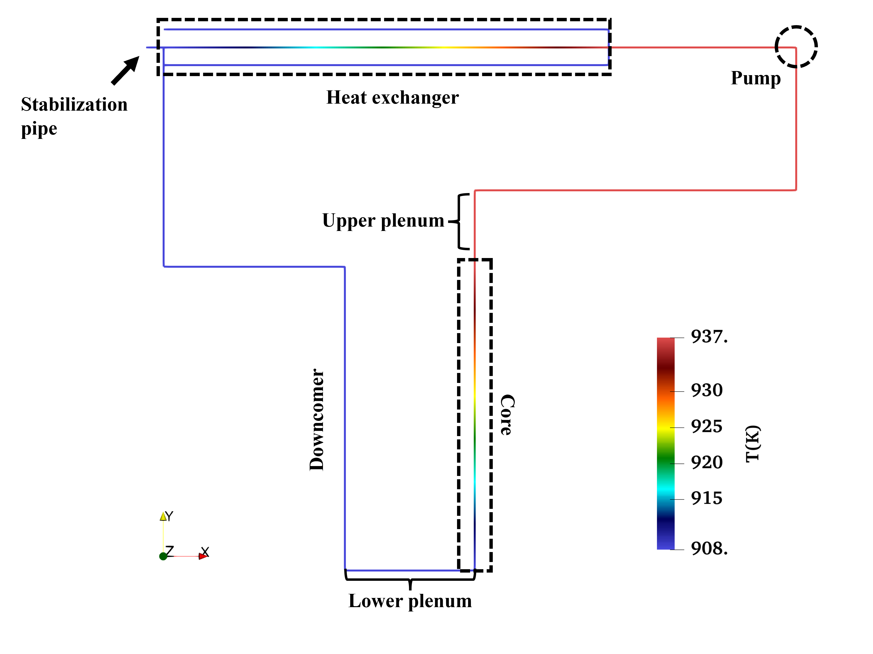
Figure 1: The steady-state temperature distribution in the 1-D MSRE primary loop.
MSRE Reactivity Insertion Test
An additional SAM model was developed for the MSRE reactivity insertion tests(Feng et al., 2021; Fei et al., 2022). There are three external reactivity insertion experiments conducted in MSRE at power levels of 1 MW, 5 MW, and 8 MW. This SAM model is developed for the 5 MW case. The SAM model consists of two calculation steps. In Step 1, the power level is adjusted to be consistent with that in the experiments. The power is kept constant for a long period of time (1000 - 2000 seconds) until the steady state condition was achieved, i.e., all parameters (density, temperature, etc.) in the system no longer change. Some preliminary scoping studies are performed to ensure the initial conditions (core inlet/outlet temperature, HX secondary side inlet/outlet temperature) are consistent with the experiments before this step. In the second step, an external reactivity is inserted at the beginning of the simulation, and power is allowed to change due to the external reactivity insertion and the reactivity feedback following the power increase. This MSRE SAM model is similar to the existing SAM model, except that the MSR-specific point kinetics is enabled and the MSRE primary heat exchanger is modeled by a PBHeatExchanger component in SAM. The Point Kinetic Equation for MSRs is employed to predict the power evolution. The delayed neutron precursor sources are specified in the core, upper and lower plenum. The power fractions in these regions are 87.5%, 3.89%, and 8.59%, respectively. The delayed neutron precursor sources are directly proportional to the power fraction in the current code implementation. Thus, to account for all delayed neutron precursors, no power is specified in the graphite moderators.
There are two reactivity feedback mechanisms considered in the model. The fuel feedback is captured with the fuel density reactivity feedback coefficient (“coolant_reactivity_coefficients”). The graphite feedback is captured with the moderator temperature feedback coefficient (“moderator_reactivity_coefficients”). The “moderator_reactivity_coefficients” is defined as the reactivity change per temperature. Thus, the mass (volume) of the moderator is specified carefully to be consistent with the MSRE graphite mass. The power transition during the insertion of external reactivity is shown in Figure 2.
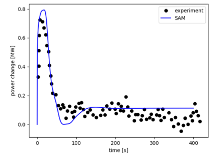
Figure 2: Power change following the external reactivity insertion.
References
- S E Beall, P N Haubenreich, R B Lindauer, and J R Tallackson.
MSRE Design and Operations Report. Part V. Reactor Safety Analysis Report.
Technical Report ORNL-TM-732, Oak Ridge National Laboratory, Oak Ridge, TN, 1964.[BibTeX]
- S Cantor.
Physical Properties of Molten-Salt Reactor Fuel, Coolant, and Flush Salts.
Technical Report ORNL-TM-2316, Oak Ridge National Laboratory, Oak Ridge, TN, 1968.
URL: https://www.osti.gov/biblio/4492893 https://www.osti.gov/servlets/purl/4492893, doi:10.2172/4492893.[BibTeX]
- Tingzhou Fei, Thanh Hua, and Bo Feng.
MSRE Reactivity Insertion Test Benchmark Using SAM.
In Transactions of 2022 ANS Winter Meeting. Pheonix, AZ, 2022. American Nuclear Society.
doi:10.13182/T127-39714.[BibTeX]
- Bo Feng, Shayan Shahbazi, Jun Fang, Ting Fei, and Dillon Shaver.
Application of NEAMS Codes to Capture MSR Phenomena.
Technical Report ANL/NSE-21/48, Argonne National Laboratory, Lemont, IL, 2021.
URL: https://www.osti.gov/biblio/1826681, doi:10.2172/1826681.[BibTeX]
- R H Guymon.
MSRE systems and components performance.
Technical Report ORNL-TM-3039, Oak Ridge National Laboratory, Oak Ridge, TN, 1973.[BibTeX]
- R C Robertson.
MSRE design and operations report. Part I. Description of reactor design.
Technical Report ORNL-TM-728, Oak Ridge National Laboratory, Oak Ridge, TN, 1965.[BibTeX]