MSFR Turbulence Modeling Parameter Tuning Using Nek5000 Data
As a coarse mesh CFD code, Pronghorn requires high fidelity data to be able to model small scale phenomena. Turbulence modeling in Pronghorn currently supports a zero-equation model, a capped mixing length model, which is a modification of the original Prandtl's mixing length model (Escudier, 1966). In this formulation, the mixing length grows linearly up to a distance dependent on a parameter , which is representative of the boundary layer thickness. Using Nek5000 data, this parameter is tuned for Reynolds numbers 40K and 1M. The latter is of particular interest to simulate the MSFR operational regime.
The mesh used for the tuning is the same as the one used in Nek5000 model.
Results for Reynolds number 40,000
The boundary conditions for this problem are velocity inlet profile, pressure outlet, symmetry at the center of the geometry along the X axis and no slip condition at the walls. Time derivatives are added to the momentum equation for relaxation purposes.
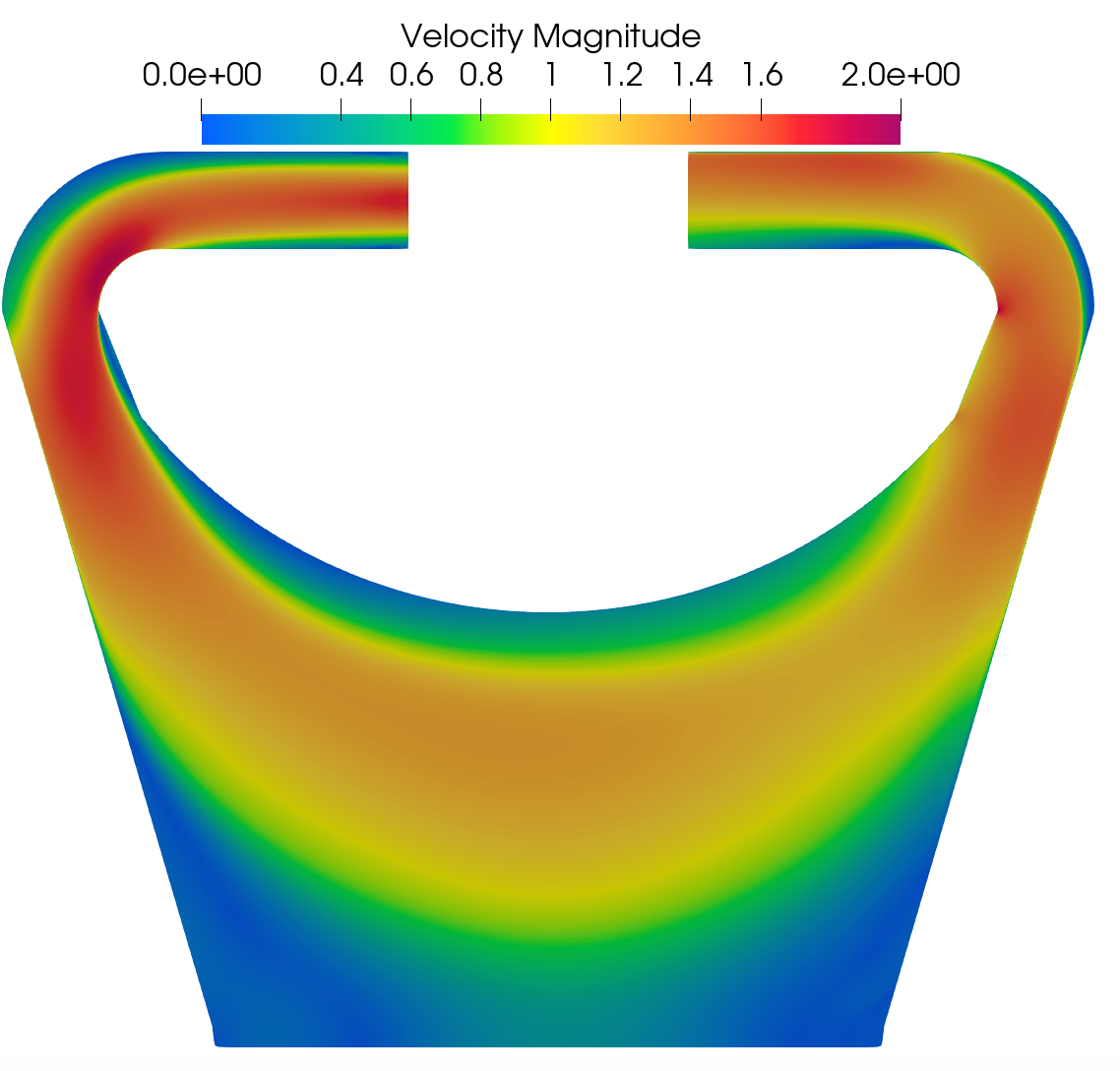
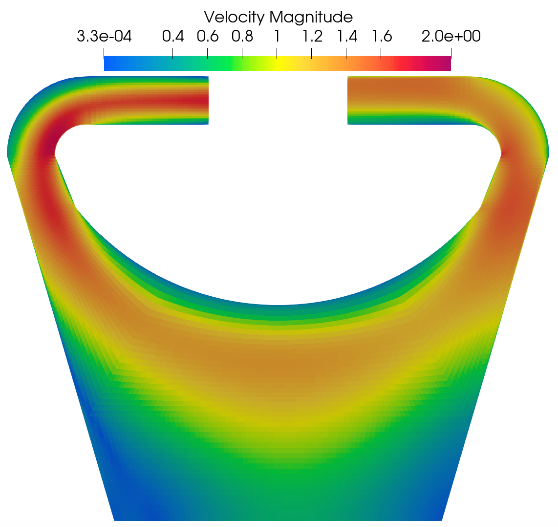
Velocity magnitude and pressure fields obtained in Nek5000 and Pronghorn are shown next.
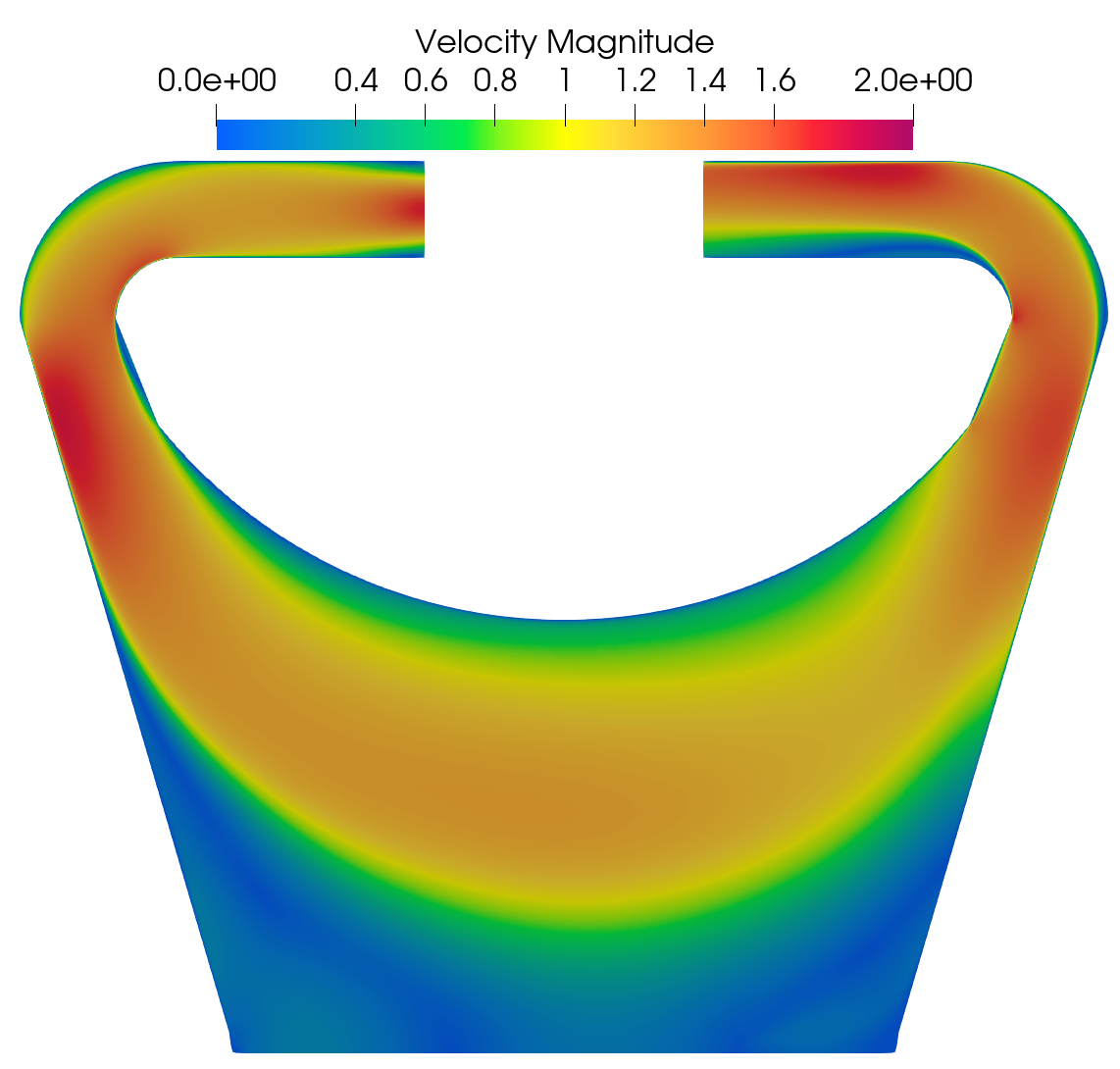
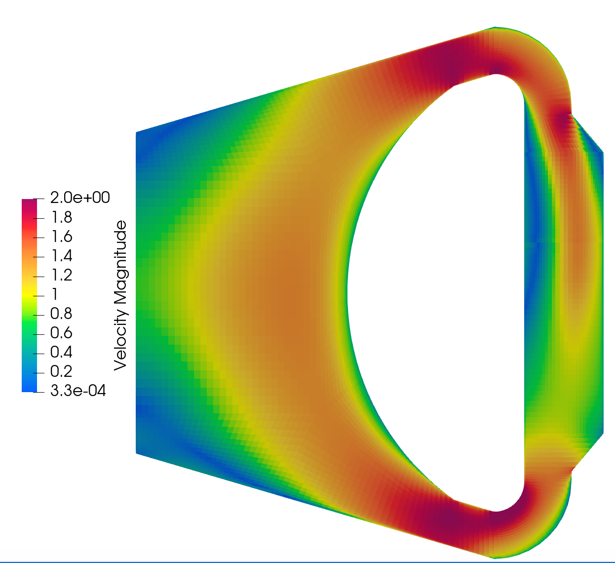
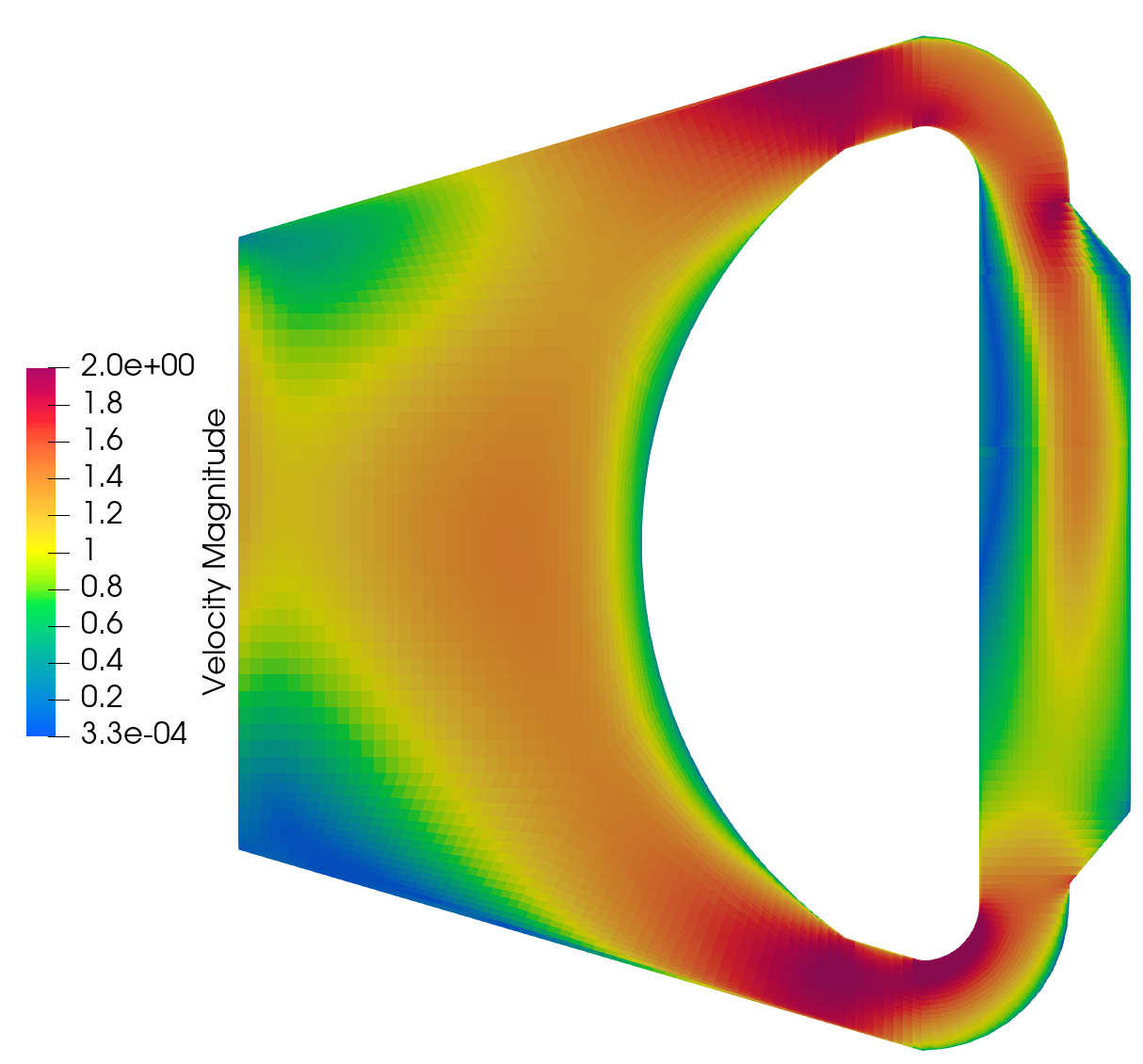
Nek5000 Velocity magnitude field for Re 40K.
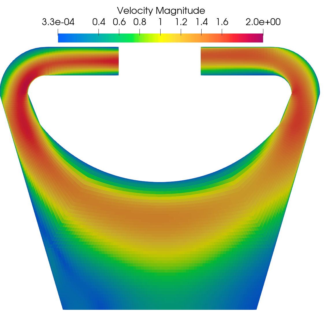
Pronghorn Velocity magnitude field for Re 40K.
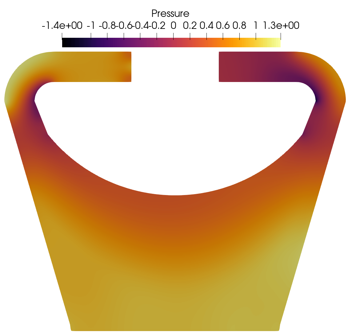
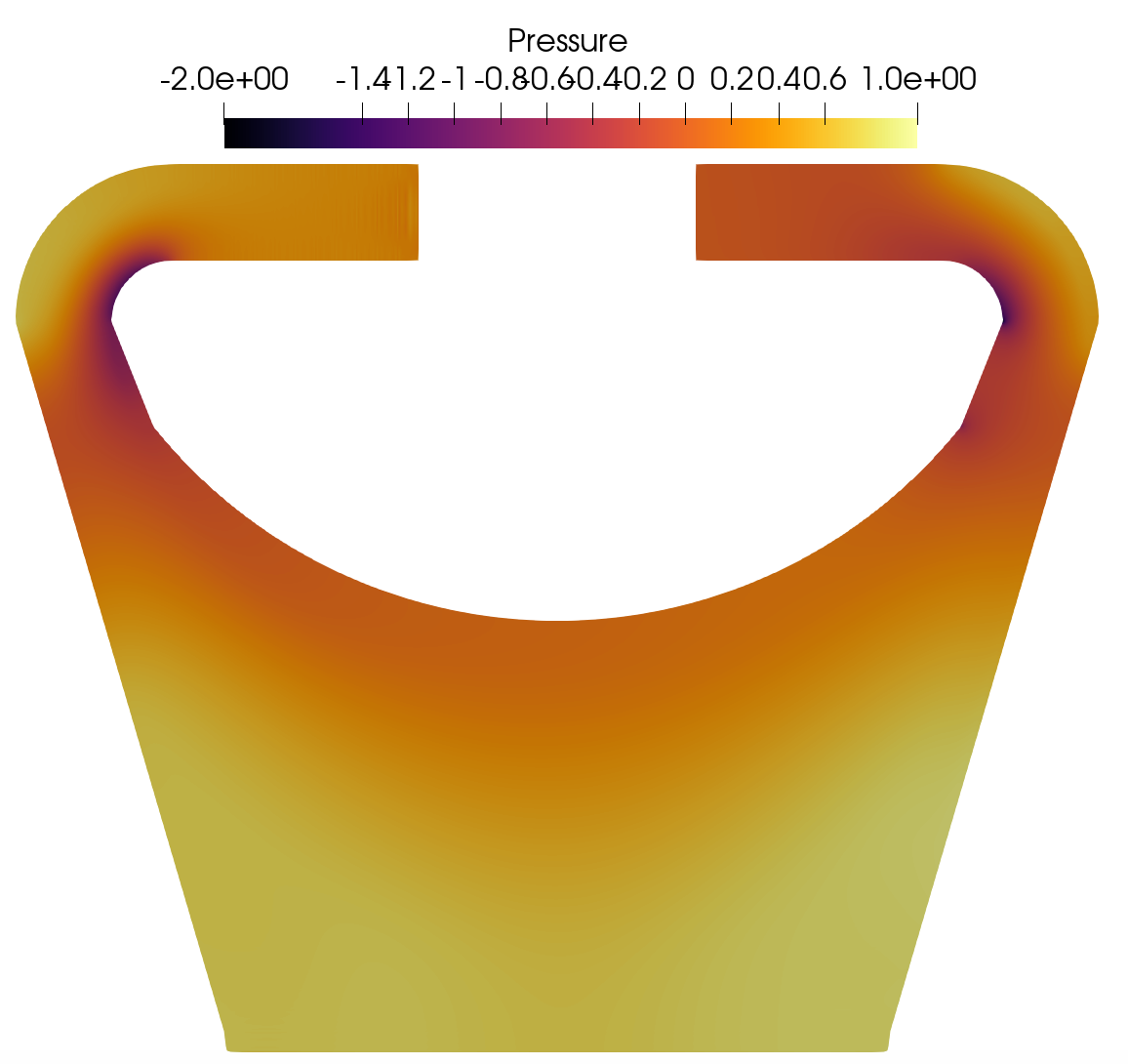
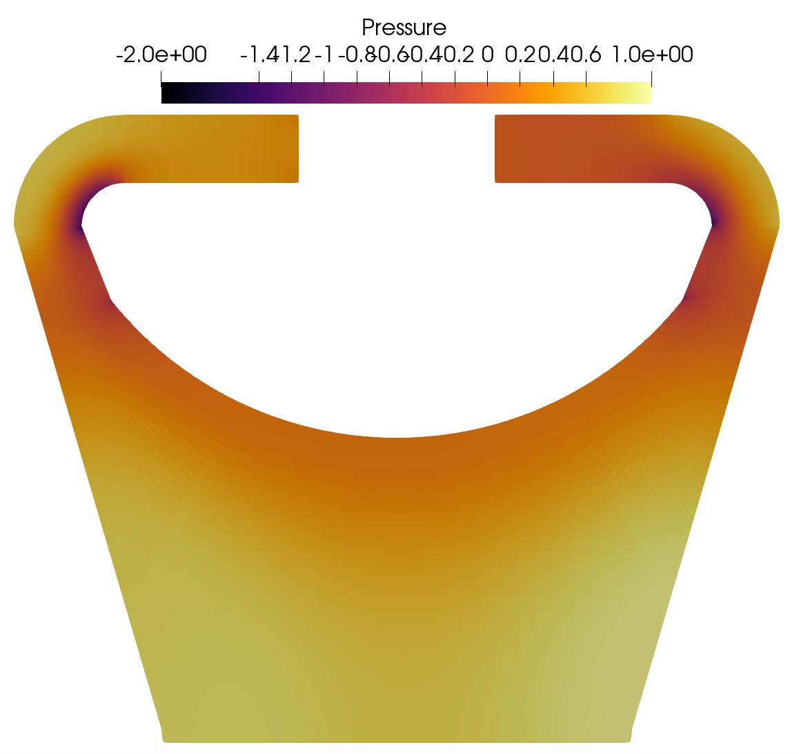
Nek5000 Pressure field for Re 40K.
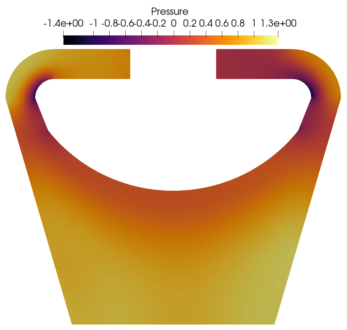
Pronghorn Pressure field for Re 40K.
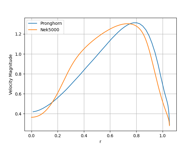
The parameter for this simulation is set to 0.12 m. This is the result of a parametric study focused on minimizing the error of the velocity field, specifically at the minimum core radius. The velocity magnitude at the minimum core radius is plotted in the following figure.
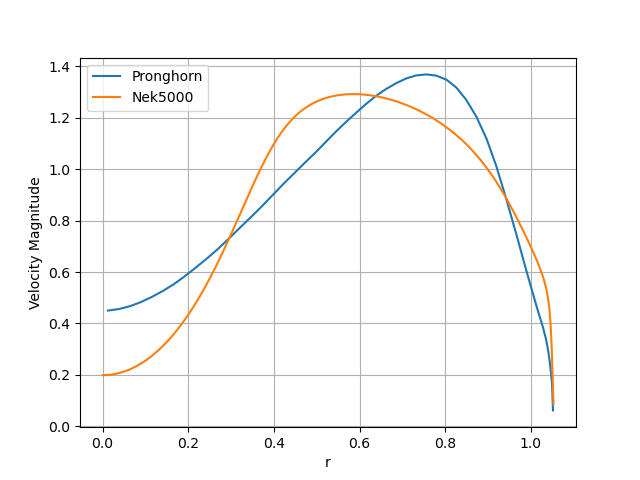
Velocity magnitude at the minimum core radius.
The behavior of the velocity fields are similar between both codes. The momentum diffusion at the core of the reactor is relatively higher in Pronghorn. This comes as a result of the limitation in the zero-equation turbulence model, which assumes a constant mixing length in the bulk region.
Pronghorn's total simulation time is 4 minutes using 4 cores.
Results for Reynolds number 1,000,000
The boundary conditions for this problem are velocity inlet profile, pressure outlet, symmetry at the center of the geometry along the X axis and standard velocity wall functions at the walls. Time derivatives are added to the momentum equation for relaxation purposes.
An exponentially decaying viscosity ramp is used for convergence purposes.
Velocity magnitude and pressure fields obtained in Nek5000 and Pronghorn are shown next.
Nek5000 Velocity magnitude field for Re 1M.
Pronghorn Velocity magnitude field for Re 1M.
Nek5000 Pressure field for Re 1M.
Pronghorn Pressure field for Re 1M.
The parameter for this simulation is set to 0.1 m. This is the result of a parametric study focused on minimizing the error of the velocity field, specifically at the minimum core radius. The velocity magnitude at the minimum core radius is plotted in the following figure.
The behavior of the velocity fields are similar between both codes. The momentum diffusion at the center of the reactor is slightly higher in Pronghorn.
Velocity magnitude at the minimum core radius.
Pronghorn's total simulation time is 15 minutes using 4 cores.
General Remarks
Even though Pronghorn offers a lower computation time, it is important to note that in a coarse mesh CFD code like Pronghorn, the tuning done in this section is dependent on the mesh due to the numerical diffusion. The importance of this numerical diffusion could be reduced in the future with the implementation of second order upwind discretization (currently using linear upwind) and the use of non-orthogonal correctors for meshes with a degree of skewness.
MSFR Griffin-Pronghorn Results
Sample outputs for this model are hosted on LFS. Please refer to LFS instructions to download them.
Initialization
The Reynolds number in the operational regime of the MSFR is around , therefore, a high degree of relaxation is needed when the initial condition is a zero velocity field. The current way of relaxing the solution starting from a zero velocity field is to ramp down the viscosity with an exponentially decaying material property function and the addition of time derivatives. To avoid this step during the fully coupled simulation, run_ns.i restarts from an exodus file (run_ns_initial_out.e) that contains the converged velocity fields. The input file which generates this initial operation regime condition is called run_ns_initial.i. The value is obtained from the comparison against Nek5000.
The steady state velocity magnitude fields for the MSFR Griffin-Pronghorn model is depicted below.
Full Model Steady State
The Griffin-Pronghorn model predicts the following steady-state velocity and temperature fields in the MSFR:
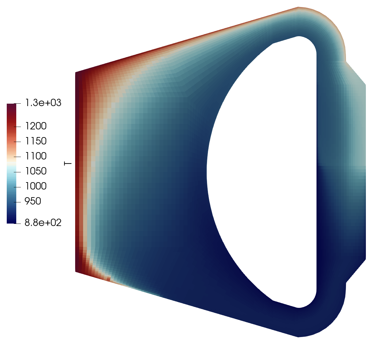
The maximum temperature of the simulation is around 1280 K. Note that despite some momentum diffusion occurring in the reactor core, the flow at the center is low where the power density has a maximum. This leads to high temperatures in the center region, which in turn drives the flow vertically through buoyancy.
We can also observe a low degree of flow separation along the shield wall. The salt here will be in direct contact with the core structure and may challenge the temperature limitations of the structural material.
The main difference between the velocity fields of the previous section and this section is the augmented flow in the core of the reactor. This is a results of the buoyant force coupling.
The Griffin-Pronghorn model also provides the steady-state distributions of the delayed neutron precursors. The distributions of 3 (of the 6) groups are shown below. For this plot, the concentrations have been normalized so that the maximum value for each group is unity.
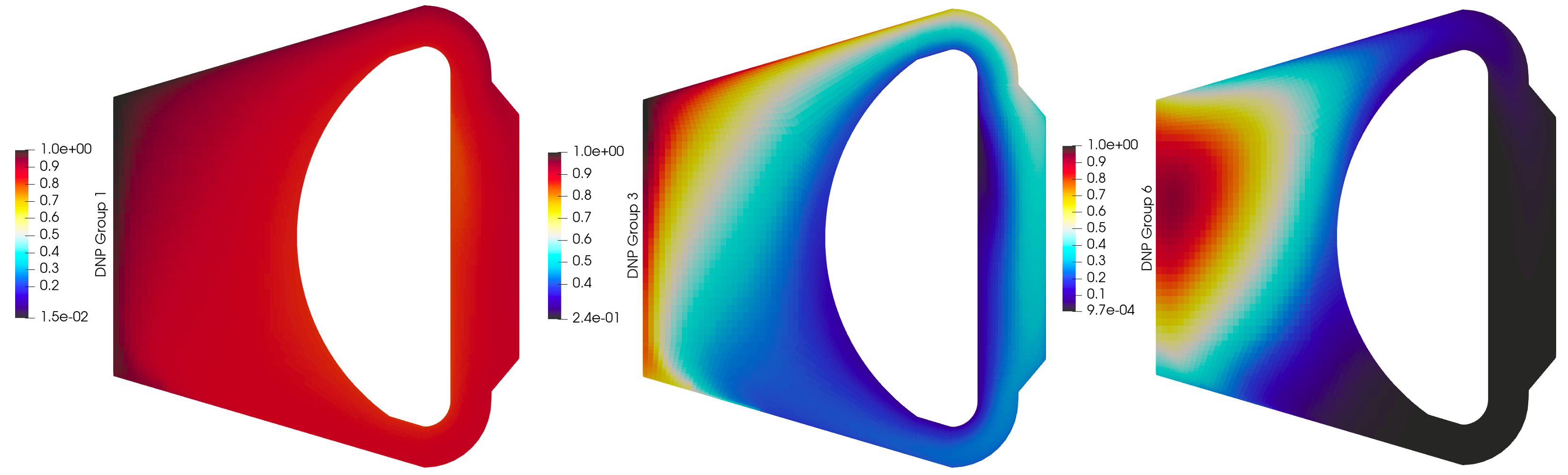
Group 6 has the shortest half-life (240 ms), and its behavior is dominated by radioactive decay rather than advection. Consequently, its distribution closely matches the fission distribution, with a distinct peak in the middle of the core. Groups 3 and 1 have longer half-lives (6 and 52 s, respectively), so they are more readily advected and diffused by the fluid. In fact, the distribution of the slowest decaying group, group 1, is nearly uniform throughout the salt.
References
- M.P Escudier.
The Distribution of Mixing-Length in Turbulent Flows Near Walls.
PhD thesis, Imperial College, 1966.[BibTeX]