Multiphysics results
A systematic multiphysics analysis was completed in the 1/6 core HP-MR model for both steady state operation and two representative types of power transients by coupling the Griffin CFEM-SN(1,3) neutronics solver, the BISON thermal physics solver, and the Sockeye heat-pipe thermal performance solver. In this section, the simulation results are discussed.
Steady State Results
At the nominal power of ~2.07 MW, the Griffin-BISON-Sockeye model predicts the steady state operating parameters shown in Table 1.
Table 1: Key HP-MR operating parameters at steady state at nominal power
| Parameter | Unit | Value |
|---|---|---|
| Thermal Power (1/6 core) | kW | 345.6 |
| Avg. Fuel Temperature | K | 846.16 |
| Max. Fuel Temperature | K | 869.99 |
| Min. Fuel Temperature | K | 821.49 |
| Avg. Moderator Temperature | K | 844.00 |
| Max. Moderator Temperature | K | 864.93 |
| Min. Moderator Temperature | K | 823.19 |
| n/a | 1.050024 |
Figure 1: Operating limits of the heat pipe used in the HP-MR
As illustrated in Figure 1, according to the operating limits predicted by the Sockeye code, the heat pipes adopted by the HP-MR operate with a major safety margin from any limits at the nominal power of the HP-MR. Therefore, a single heat pipe failure is expected to be localized and the neighboring heat pipes have abundance margins to remove this extraneous heat. To demonstrate the capability of the model to predict a heat pipe cascade failure event, steady state parameters of the HP-MR operating at an overpower of ~4.32 MW are also computed as follows in Table 2. Running at overpower naturally leads to a higher operating temperature and reduced reactivity.
Table 2: Key HP-MR operating parameters at steady state at an overpower level
| Parameter | Unit | Value |
|---|---|---|
| Thermal Power (1/6 core) | kW | 720 |
| Avg. Fuel Temperature | K | 896.41 |
| Max. Fuel Temperature | K | 946.39 |
| Min. Fuel Temperature | K | 844.89 |
| Avg. Moderator Temperature | K | 891.75 |
| Max. Moderator Temperature | K | 935.43 |
| Min. Moderator Temperature | K | 848.50 |
| n/a | 1.048425 |
Load Following Transient Results
The loading following transient is initiated by a significant reduction in the heat removal capability of the secondary coolant loop. As a result, temperature of the heat pipe increases as the heat cannot be transferred to the secondary coolant loop effective, which eventually leads to the increase in core temperature (see Figure 2). Through the negative temperature reactivity feedback, the power of the HP-MR drops subsequently as illustrated in Figure 3.
Figure 2: Time evoluation of predicted 1/6 core average fuel and moderator temperatures during the loading following transient
Figure 3: Time evoluation of predicted 1/6 core power during the loading following transient
Based on the transient simulation that lasts for 2,000 seconds, the trend is prominent that the HP-MR power drops to a lower level (from originally 2.07 MW to ~0.3 MW), with a slight increase in core temperature.
Localized Single Heat Pipe Failure Transients
When the HP-MR is operating at its nominal power, the central heat pipe of the innermost assembly is artificially set as failure. The Griffin-BISON-Sockeye multiphysics simulation predicts that the single heat pipe failure event can be localized. Namely, the surrounding heat pipes are capable of removing the extraneous heat effectively. Thus, the average core temperature only experiences a minor change (less than 1 K) as shown in Figure 4. On the other hand, the local temperature near the failed heat pipe does increase by approximately 10 K (see Figure 5). Consequently, this localized temperature increase only leads to a minor power drop of ~1% as illustrated in Figure 6.
Figure 4: Time evoluation of predicted 1/6 core average fuel and moderator temperatures during the localized single heat pipe failure transient
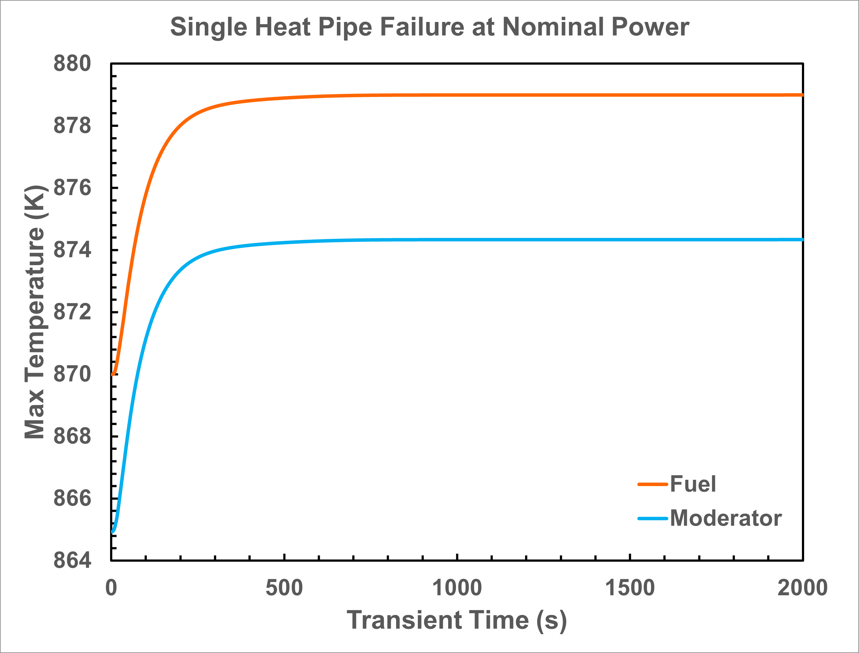
Figure 5: Time evoluation of predicted 1/6 core maximum fuel and moderator temperatures during the localized single heat pipe failure transient
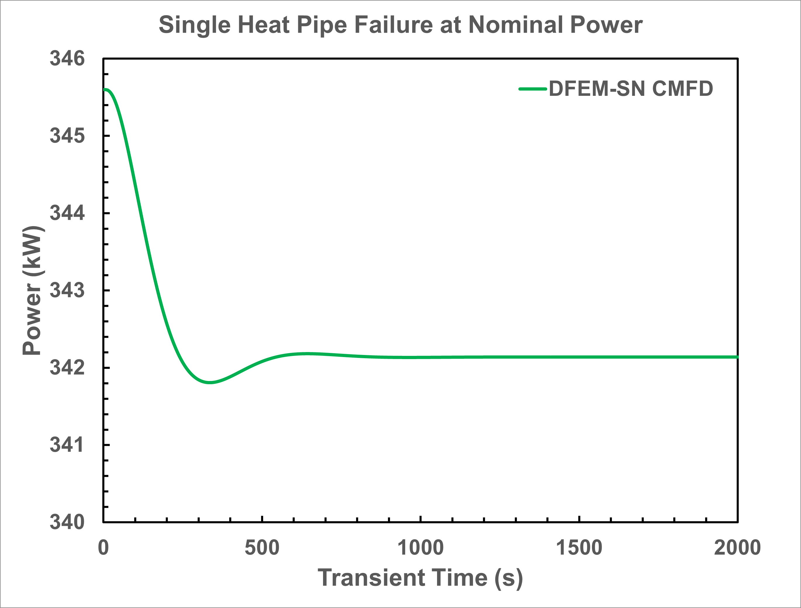
Figure 6: Time evoluation of predicted 1/6 core power during the localized single heat pipe failure transient
Based on this simulation results, the single heat pipe failure event in an HP-MR operating at its nominal power is benign and the microreactor may operate with the failed heat pipe.
Heat Pipe Cascade Failure Transient
On the other hand, when the HP-MR is operating at an overpower level that push the heat pipes' capacity near their limit. The introduction of a single heat pipe failure is predicted by the model to initiate a cascade failure event. As shown in the snapshots in Figure 7, six, twelve, twenty-four, and thirty heat pipes adjascent to the initial failed heat pipe are predicted to failed after 125, 250, 600 and 1,000 seconds since the first heat pipe fails. As a result, the innermost assembly lost the majority of its heat removal methods and suffers high temperature that exceeds 1,000 K. The HPMR power also drops prominently through reactivity feedback. Therefore, during HPMR design, the power needs to be wisely decided to make sure that the heat pipe has an abundant margin from its limit to prevent such cascade failure.
Figure 7: Heat pipe cascade failure predicted by the model when an overpowered HP-MR encounters a single heat pipe failure event