GCMR Assembly Multiphysics Model
Point of Contact: Ahmed Abdelhameed (aabdelhameed.at.anl.gov), Yinbin Miao (ymiao.at.anl.gov), Nicolas Stauff (nstauff.at.anl.gov)
Model link: GCMR Assembly Model
Mesh files
The meshes for this model are hosted on LFS. Please refer to LFS instructions
The 3-D mesh for the GC-MR assembly displayed in Figure 1 was generated by MOOSE intrinsic meshing tools available in the Reactor module. This MOOSE-based tool allows a direct construction of assembly or reactor core mesh from simple cartesian and hexagonal unit geometries. The Reactor Module consists of a series of mesh generators to enable meshing of reactor cores. Using MOOSE mesh generators for constructing meshes for reactor geometries entails following the intrinsic geometric hierarchy where the unit cartesian or hexagonal structures (e.g., unit pin-cell structures of control rod, fuel pin) can be assembled into fuel assemblies. The objects in Reactor Module provides direct control of mesh/element size through the input parameters. Adjusting the mesh density from coarse to fine takes little time, streamlining sensitivity analyses on mesh refinement. The consistency between the geometrical representations in the mesh file and the cross-section generation code was verified by directly comparing the volumes of the different blocks/universes. In this example, only the fine mesh is needed for the Griffin input, which is given in Griffin_mesh.e, and Griffin generates the coarse mesh required for the CMFD acceleration as such:
[Mesh]
  [fmg]
    type = FileMeshGenerator
    file = '../MESH/Griffin_mesh.e'
  []
  [fmg_id]
    type = SubdomainExtraElementIDGenerator
    input = fmg
    subdomains = '10 100 102 103 200 201 300 400 401 500 600 8000 8001'
    extra_element_id_names = 'material_id equivalence_id'
    extra_element_ids = '803 802 810 806 807 807 804 801 801 808 809 805 805;
                         803 802 810 806 807 807 804 801 801 808 809 805 805'
  []
  [coarse_mesh]
    type = GeneratedMeshGenerator
    dim = 3
    nx = 10
    ny = 10
    nz = 20
    xmin = -0.1
    xmax = 0.1
    ymin = -0.1
    ymax = 0.1
    zmin = 0.
    zmax = 2.
  []
  [assign_coarse_id]
    type = CoarseMeshExtraElementIDGenerator
    input = fmg_id
    coarse_mesh = coarse_mesh
    extra_element_id_name = coarse_element_id
  []
[]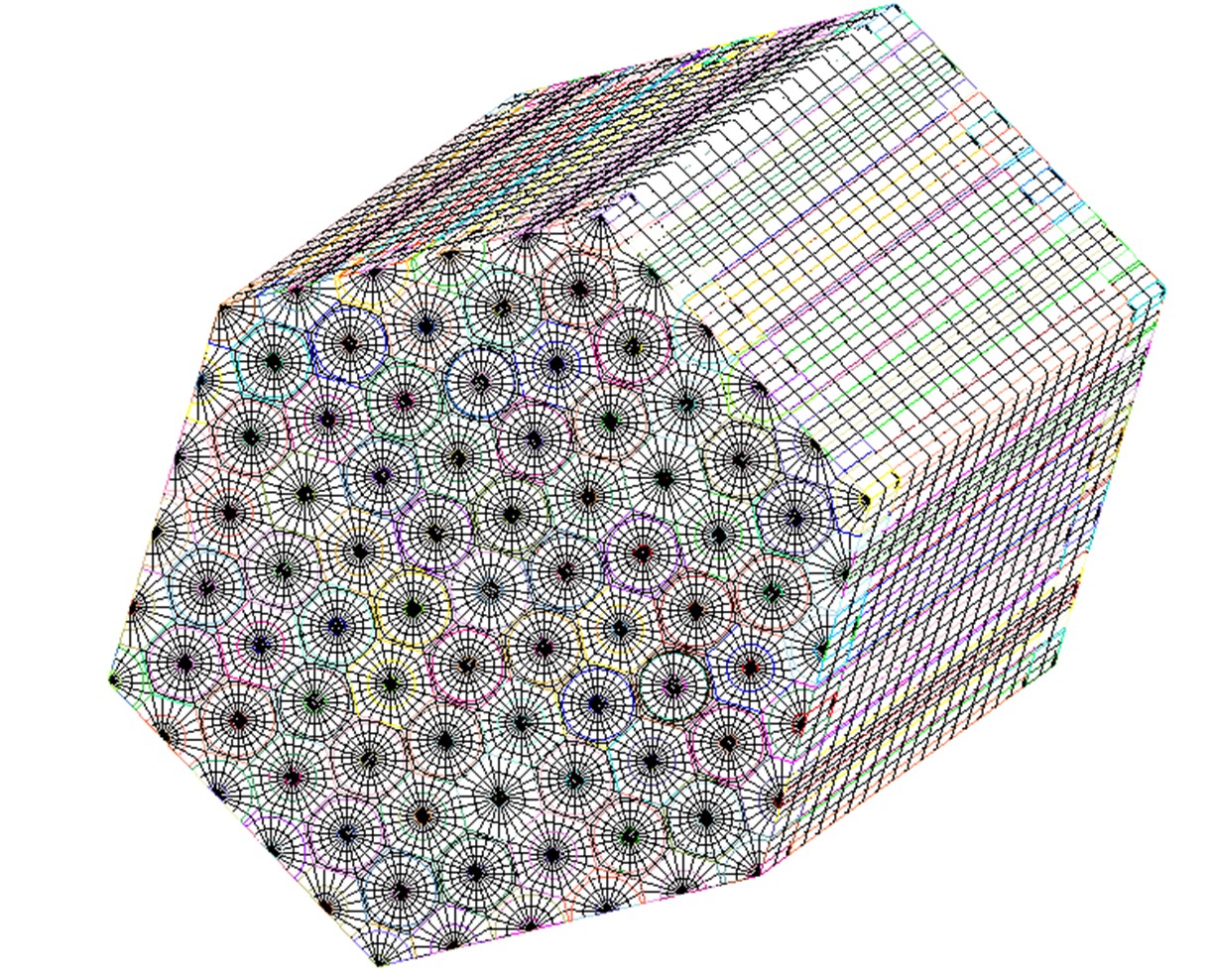
Figure 1: Three-D mesh representation of the GC-MR assembly
For analysis of the multi-physics, BISON and SAM were coupled with Griffin. A different mesh file were used BISON_mesh.e in which the coolant channels where removed from the 3-D solid mesh, as the coolant channels were handled separately by SAM. It should be noticed that BISON and SAM are coupled through coolant channel surface.
Griffin Model
For modeling the GC-MR Assembly in 3-D, the neutron transport equation was solved by Griffin using the discrete ordinates SN method for the angular discretization while the discontinuous finite method (DFEM) method was used for the spatial discretization (Abdelhameed et al., 2022) (Stauff et al., 2022). The coarse mesh finite element method (CMFD) acceleration was used to speed up the DFEM solver. On-the-fly coarse mesh generation is done with Griffin. This means that the user doesn’t need to provide a separate coarse mesh file for the calculations. In Griffin, the coarse element IDs of elements on the fine mesh are assigned through overlaying a regular grid, i.e., the elements whose centroids falls into the same regular grid are assigned with the same coarse element ID.
The homogenized multigroup cross-sections were generated using Serpent-2 with ENDF/B-VII.1 data library and then converted to XML-format cross section file and they functionalized with the fuel temperature for eleven energy groups structure. These multigroup structures were generated for the beginning of the cycle condition. The process of generating the multi-group cross-sections using Serpent-2 is outside the scope of this example. The multi-group cross-sections for the various materials are assigned to fill the various blocks of the mesh file. In this problem the materials_id of each material is given one of the numbers from 801 to 810. While the numbers of the mesh blocks are: 10, 100, 102, 103, 200, 201, 300, 400, 401, 500, 600, 8000, and 8001. They are specified in the [Mesh] block as follows:
    subdomains = '10 100 102 103 200 201 300 400 401 500 600 8000 8001'
    extra_element_id_names = 'material_id equivalence_id'
    extra_element_ids = '803 802 810 806 807 807 804 801 801 808 809 805 805;
803 802 810 806 807 807 804 801 801 808 809 805 805'While CoupledFeedbackMatIDNeutronicsMaterial material type was used in the [Materials] block:
[Materials]
  [mod]
    type = CoupledFeedbackMatIDNeutronicsMaterial
    block = '10 100 102 103 200 201 300 400 401 500 600 8000 8001'
    library_file = '../ISOXML/XS_Griffin.xml'
    library_name = XS_Griffin
    isotopes = 'pseudo'
    densities = 1.0
    is_meter = true
    # power normalization
    plus = true
    dbgmat = false
    grid_names = 'Tmod'
    grid_variables = 'Tf'
  []
[]Griffin reads the XML-format cross-section file, XS_Griffin, and a mesh file Griffin_mesh.e that specifies the 3-D mesh which has the same geometry as the one used in the cross-section generation code. The consistency between the volumes of the different materials in the Serpent-2 model and in the 3-D mesh were directly compared to verify the geometrical consistency.
The 3-D GC-MR assembly was solved with reflective boundary condition radially and vacuum boundary conditions axially on the top and bottom reflector boundaries. In both the steady-state and the transient Griffin calculations, the DFEM-SN with CMFD was used. Because good accuracy was obtained with the eleven energy groups structure, only small numbers of polar and azimuthal angles were used with the SN solver:
[TransportSystems]
  particle = neutron
  equation_type = eigenvalue

  G = 11
  VacuumBoundary = '2000 2001'
  ReflectingBoundary = '9000'

  [SN]
    scheme = DFEM-SN
    family = MONOMIAL
    order = FIRST

    AQtype = Gauss-Chebyshev
    NPolar = 2
    NAzmthl = 3
    NA = 2
    n_delay_groups = 6

    using_array_variable = true
    collapse_scattering = true
    hide_angular_flux = true
  []
[]BISON Model
BISON enables thermal-mechanical computation of a reactor core that consists of multiple components/materials, and it was employed to model the heat conduction of the GC-MR assembly. BISON contains a solid list of material properties that are applied in this model, including a recent update of graphite properties. These models include: GraphiteGradeCreepUpdate, GraphiteGradeElasticityTensor, GraphiteGradeIrradiationEigenstrain, GraphiteGradeThermalExpansionEigenstrain, GraphiteMatrixThermal, and GraphiteMatrixThermalExpansionEigenstrain. The updated GraphiteMatrixThermal that computes thermal conductivity (W/m/K) and specific heat capacity (J/kg/K). The BISON input files for steady-state and transient cases are BISON.i and BISON_tr, respectively. The positions of the coolant channels was specified in BISON.i and BISON_tr files as such:
coolant_full_points_filename = ../channel_positions/coolant_full_points.txt # File containing the inlet position of your coolant channels
coolant_half_points_filename = ../channel_positions/coolant_half_points.txt # File containing the inlet position of your coolant channelsThe modelled assembly contains locations at which the full coolant channel is represented and in other locations, at the radial boundary, where only half coolant channel is considered. The files coolant_full_points.txt and coolant_half_points.txt include the positions of the full and half coolant channels, respectively. The full coolant channels positions are given as follows:
-0.034641, 0.060000, 0.000000
-0.000000, 0.060000, 0.000000
0.034641, 0.060000, 0.000000
-0.051962, 0.030000, 0.000000
-0.017321, 0.030000, 0.000000
0.017321, 0.030000, 0.000000
0.051962, 0.030000, 0.000000
-0.069282, -0.000000, 0.000000
-0.034641, -0.000000, 0.000000
0.034641, -0.000000, 0.000000
0.069282, -0.000000, 0.000000
-0.051962, -0.030000, 0.000000
-0.017321, -0.030000, 0.000000
0.017321, -0.030000, 0.000000
0.051962, -0.030000, 0.000000
-0.034641, -0.060000, 0.000000
-0.000000, -0.060000, 0.000000
0.034641, -0.060000, 0.000000
SAM Model
The System Analysis Module (SAM) is a modern system analysis tool being developed by the NEAMS program for advanced non-LWR safety analysis. SAM was chosen as the system-level thermal-hydraulics code due to its capability to model 1D flow-channels at low computational cost. The coolant flow and conduction through the solid structures were modeled through a coupled SAM 1D Fluid – 3D solid simulation with a convective boundary condition at the solid-fluid interface. Temperatures are exchanged at the interface through the MOOSE MultiApps and Transfers systems. The SAM model utilized its built-in Helium material properties, along with 1D fluid components PBOneDFluidComponent to simulate the fluid flow of multiple helium coolant channels across the assembly. Additionally, to enable heat transfer between the fluid and solid domains at every time step through the MOOSE transfer system, SAM’s HeatTransferWithExternalHeatStructure component along LayeredAverage user objects were employed. For steady-state calculations the SAM_full.i and SAM_half.i are the SAM input files for full and half coolant channels, respectively.
Multiphysics Coupling
Multiphysics simulations performed on microreactor models leverage the MOOSE MultiApp system to couple neutronics (Griffin), heat conduction in solid materials (BISON), and coolant channel heat energy transfers (SAM). The coupling logic of these different codes is shown in Figure 2. Each code has its own mesh and corresponding space and time scales.
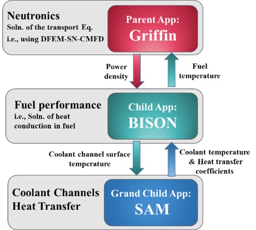
Figure 2: MultiApp modeling strategy
The 3-D power density distribution is calculated by Griffin and transferred to BISON for performing heat conduction calculations to estimate the fuel temperature. The coolant channels are modelled with SAM to estimate the coolant temperature distributions in all coolant channels. The MOOSE Picard fixed point iteration was used to attain a tightly coupled simulation, where the information is transferred back and forth between the three MOOSE-based applications until convergence of the power source distribution. The MultiApps blocks in Griffin_steady_state.i and BISON.i specify the MuliApp coupling for steady-state calculations, and the MultiApps blocks in Griffin_transient.i ` and
`BISON_tr.i specifies the MultiApp coupling for the transient problem. The Transfer system defined in the Transfers blocks, takes care of data interchange between the different applications, and controls what type of information is transferred and how the transfer will occur.
The power density and fuel temperatures transferred are defined through the Transfer system. Transfers block in the parent App (Griffin), where MultiAppProjectionTransfer was used which performs a projection between the parent App and the child App mesh files while conserving the integral of the transferred data. This is suitable for this case since the BISON_mesh.e and Griffin_mesh.e are only slightly different. However, generally, if the meshes are different, the MultiAppShapeEvaluationTransfer is recommended.
[Transfers]
  [to_sub_power_density]
    type = MultiAppGeneralFieldShapeEvaluationTransfer
    to_multi_app = bison
    variable = power_density
    source_variable = power_density
    execute_on = 'timestep_end'
    displaced_source_mesh = false
    displaced_target_mesh = false
    use_displaced_mesh = false
  []
  [from_sub_temp]
    type = MultiAppGeneralFieldNearestLocationTransfer
    from_multi_app = bison
    variable = Tf
    source_variable = Tfuel
    execute_on = 'timestep_end'
    use_displaced_mesh = false
  []
[]References
- Ahmed Amin Abdelhameed, Yan Cao, Daniel Nunez, Yinbin Miao, Kun Mo, Changho Lee, Emily Shemon, and Nicolas E. Stauff.
High-fidelity multiphysics modeling of load following for 3-d gas-cooled microreactor assembly using neams codes.
In Proceedings of the ANS Winter. 2022.[BibTeX]
- Nicolas E. Stauff, Ahmed Amin Abdelhameed, Yan Cao, Daniel Nunez, Yinbin Miao, Kun Mo, Changho Lee, Christopher Matthews, Emily Shemon, and Justin Thomas.
Applications of neams codes for multiphysics modeling of several microreactors problems.
In Proceedings of the ANS Winter. 2022.[BibTeX]