Balance of Plant system
The simulated reactor is a HTGR (High Temperature Gas cooled Reactor). Its thermal power is 15 MWth, and the generator must produce 2 MWe. The system couples a helium-cooled primary loop with an open-air Brayton cycle. It is illustrated in Figure 1, and the operating conditions are provided in Table 1:
Table 1: Operating conditions
| Operating conditions | Values |
|---|---|
| Total core power | 15 MWth |
| Primary mass flow rate | 9.4 kg/s |
| Core inlet temperature | 890 K |
| Core outlet temperature | 1190 K |
| Primary system pressure | 9.10^6 Pa |
| Secondary mass flow rate | 20 kg/s |
| Secondary heat exchanger inlet temperature | 490 K |
| Compressor pressure ratio | 8.9 |
| Turbine pressure ratio | 4.1 |
| Generator power | 2 MWe |
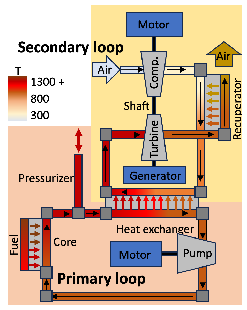
Figure 1: Design of the primary and secondary loops
Primary loop
The primary loop is constituted of a core, a heat exchanger, and a pump to compensate the pressure drop. The coolant is helium. The core design taken from (Duchnowski et al., 2022). It is composed of 55 hexagonal fuel assemblies. Their characteristics are given in Table 2. The core cross section is shown in Figure 2.
Table 2: Core components characteristics
| Component | Parameter | Value |
|---|---|---|
| Fuel channels | Radius (m) | 0.00794 |
| - | Number per assembly | 42 |
| - | Matrix material | H-451 Graphite |
| - | UN TRISO packing fraction | 0.5 |
| Coolant channels | Radius (m) | 0.00635 |
| - | Number per assembly | 18 |
| - | Coolant gas | Helium |
| Other flow channels | Diameter (m) | 0.24 |
| Assembly | Lattice pitch (m) | 0.022 |
| - | Height (m) | 2 |
| Core | Diameter (m) | 0.9 |
| - | Number of assemblies | 55 |
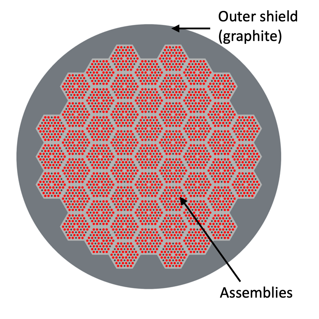
Figure 2: Core pattern
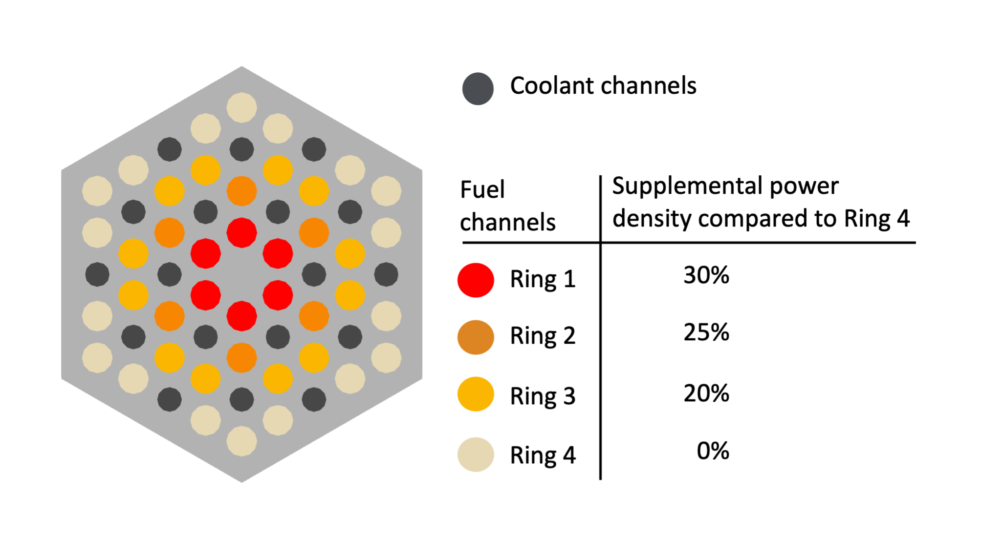
Figure 3: Assembly pattern
Secondary loop
An open-air recuperated Brayton cycle is used as secondary loop.
Air enters the loop by a compressor. The pressure is increased from the atmospheric pressure to 5.8 bar. The air is then heated first by the exhaust gases in a recuperator and secondly in a heat exchanger. In this component, 15 MWth are transferred from the primary to the secondary loop and the air temperature increases from 495 K to 1175 K. The gases go through a turbine, spinning the generator that delivers 2 MWe. The turbine rotation also drives the compressor rotation. The exhaust gases transfer a part of their residual heat in the recuperator and are finally released outside.
Before this steady state, a motor is used to launch the compressor and the turbine, which are on the same shaft. This shaft is initially at rest and reaches a rotation speed about 9500 rad/s during the steady sate. To do this, the motor torque increases quickly during the first few seconds and then decreases slowly to zero once the turbine is launched.
The secondary loop pipes diameter is 35 cm. It has been chosen not to be too large and in the same time to be able to conduct a 20 kg/s mass flow rate. Consequently, it should not be too small to avoid velocities over the sound velocity associated with the pressure and temperature conditions.
Startup and load follow transients
Two different transients are tested on this system:
a startup transient: a constant 15 MWth power is imposed in the core. The goal is to see how the system reaches its normal operating conditions.
a load follow transient: the system starts from the operating conditions for a 15 MWth power. Two modulations are then imposed:
- the core power is decreased to 80% of its normal power.
- once a new steady state is reached, the core power is set again to 15 MWth.
The start-up transient is a prerequisite to the load follow transient.
References
- Edward M. Duchnowski, Robert F. Kile, Kenny Bott, Lance L. Snead, Jason R. Trelewicz, and Nicholas R. Brown.
Pre-conceptual high temperature gas-cooled microreactor design utilizing two-phase composite moderators. part i: microreactor design and reactor performance.
Progress in Nuclear Energy, 2022.[BibTeX]