2D Generic Heat Pipe Microreactor (gHPMR) Model Mesh
This meshing script generates a mesh in a coarse form. Convergence studies for the physics of interest should be performed by the user.
The 2D generic Heat Pipe Microreactor (gHPMR) Model Mesh is created in several steps:
The fuel pin cell and heat pipe pin cell meshes are generated.
The fuel assembly meshes are created.
The core mesh is generated from the lattice of assembly meshes.
The control drum meshes are generated and translated to account for each drum position and placement in the core.
The reflector mesh is generated.
The final 2D core mesh is generated including outer reactor vessel boundary.
A more detailed explanation of each step follows below.
Fuel Pin Cell Meshes
First, there are 5 fuel pin meshes that are generated - 4 are for assemblies without a control rod channel and 1 for an assembly with a control rod channel.
  [fuel_pin_R0]
    type = PolygonConcentricCircleMeshGenerator
    num_sides = 6
    flat_side_up = false
    num_sectors_per_side = '${pin_cell_sectors_per_side}'
    polygon_size = '${cell_apothem}'
    ring_radii = '${fuel_pin_radius}'
    ring_intervals = '${num_cell_ring_intervals}'
    ring_block_ids = '${fuel_R0_tri_block_id}'
    ring_block_names = '${fuel_R0_tri_block_name}'
    background_intervals = 1
    background_block_ids = '${monolith_quad_block_id}'
    background_block_names = '${monolith_quad_block_name}'
    preserve_volumes = on
  []
  [fuel_pin_R1]
    type = PolygonConcentricCircleMeshGenerator
    num_sides = 6
    flat_side_up = false
    num_sectors_per_side = '${pin_cell_sectors_per_side}'
    polygon_size = '${cell_apothem}'
    ring_radii = '${fuel_pin_radius}'
    ring_intervals = '${num_cell_ring_intervals}'
    ring_block_ids = '${fuel_R1_tri_block_id}'
    ring_block_names = '${fuel_R1_tri_block_name}'
    background_intervals = 1
    background_block_ids = '${monolith_quad_block_id}'
    background_block_names = '${monolith_quad_block_name}'
    preserve_volumes = on
  []
  [fuel_pin_R2]
    type = PolygonConcentricCircleMeshGenerator
    num_sides = 6
    flat_side_up = false
    num_sectors_per_side = '${pin_cell_sectors_per_side}'
    polygon_size = '${cell_apothem}'
    ring_radii = '${fuel_pin_radius}'
    ring_intervals = '${num_cell_ring_intervals}'
    ring_block_ids = '${fuel_R2_tri_block_id}'
    ring_block_names = '${fuel_R2_tri_block_name}'
    background_intervals = 1
    background_block_ids = '${monolith_quad_block_id}'
    background_block_names = '${monolith_quad_block_name}'
    preserve_volumes = on
  []
  [fuel_pin_R3]
    type = PolygonConcentricCircleMeshGenerator
    num_sides = 6
    flat_side_up = false
    num_sectors_per_side = '${pin_cell_sectors_per_side}'
    polygon_size = '${cell_apothem}'
    ring_radii = '${fuel_pin_radius}'
    ring_intervals = '${num_cell_ring_intervals}'
    ring_block_ids = '${fuel_R3_tri_block_id}'
    ring_block_names = '${fuel_R3_tri_block_name}'
    background_intervals = 1
    background_block_ids = '${monolith_quad_block_id}'
    background_block_names = '${monolith_quad_block_name}'
    preserve_volumes = on
  []
  [fuel3_pin]
    type = PolygonConcentricCircleMeshGenerator
    num_sides = 6
    flat_side_up = false
    num_sectors_per_side = '${pin_cell_sectors_per_side}'
    polygon_size = '${cell_apothem}'
    ring_radii = '${fuel_pin_radius}'
    ring_intervals = '${num_cell_ring_intervals}'
    ring_block_ids = '${fuel3_tri_block_id}'
    ring_block_names = '${fuel3_tri_block_name}'
    background_intervals = 1
    background_block_ids = '${monolith_quad_block_id}'
    background_block_names = '${monolith_quad_block_name}'
    preserve_volumes = on
  []
  # Call it a pin so we know it is a pin cell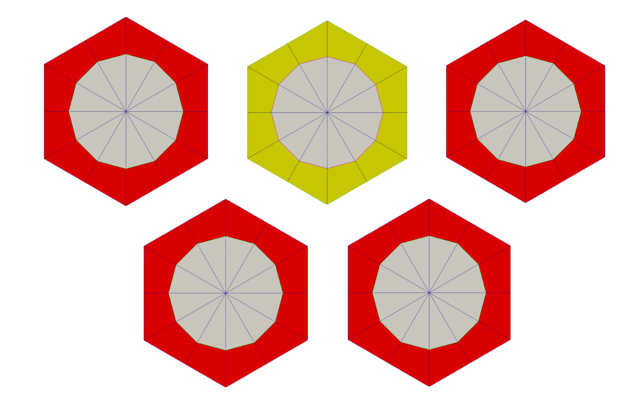
Figure 1: The five 2D fuel pin cell meshes; the yellow pin mesh is the pin used in the fuel assembly which contains a control rod channel.
Then a pin cell mesh is generated for the heat pipe.
[Mesh]
  [heat_pipe_pin]
    type = PolygonConcentricCircleMeshGenerator
    num_sides = 6
    flat_side_up = false
    num_sectors_per_side = '${pin_cell_sectors_per_side}'
    polygon_size = '${cell_apothem}'
    ring_radii = '${heat_pipe_radius}'
    ring_intervals = '${num_cell_ring_intervals}'
    ring_block_ids = '${heat_pipe_tri_block_id}'
    ring_block_names = '${heat_pipe_tri_block_name}'
    background_intervals = 1
    background_block_ids = '${monolith_quad_block_id}'
    background_block_names = '${monolith_quad_block_name}'
    preserve_volumes = on
  []
[]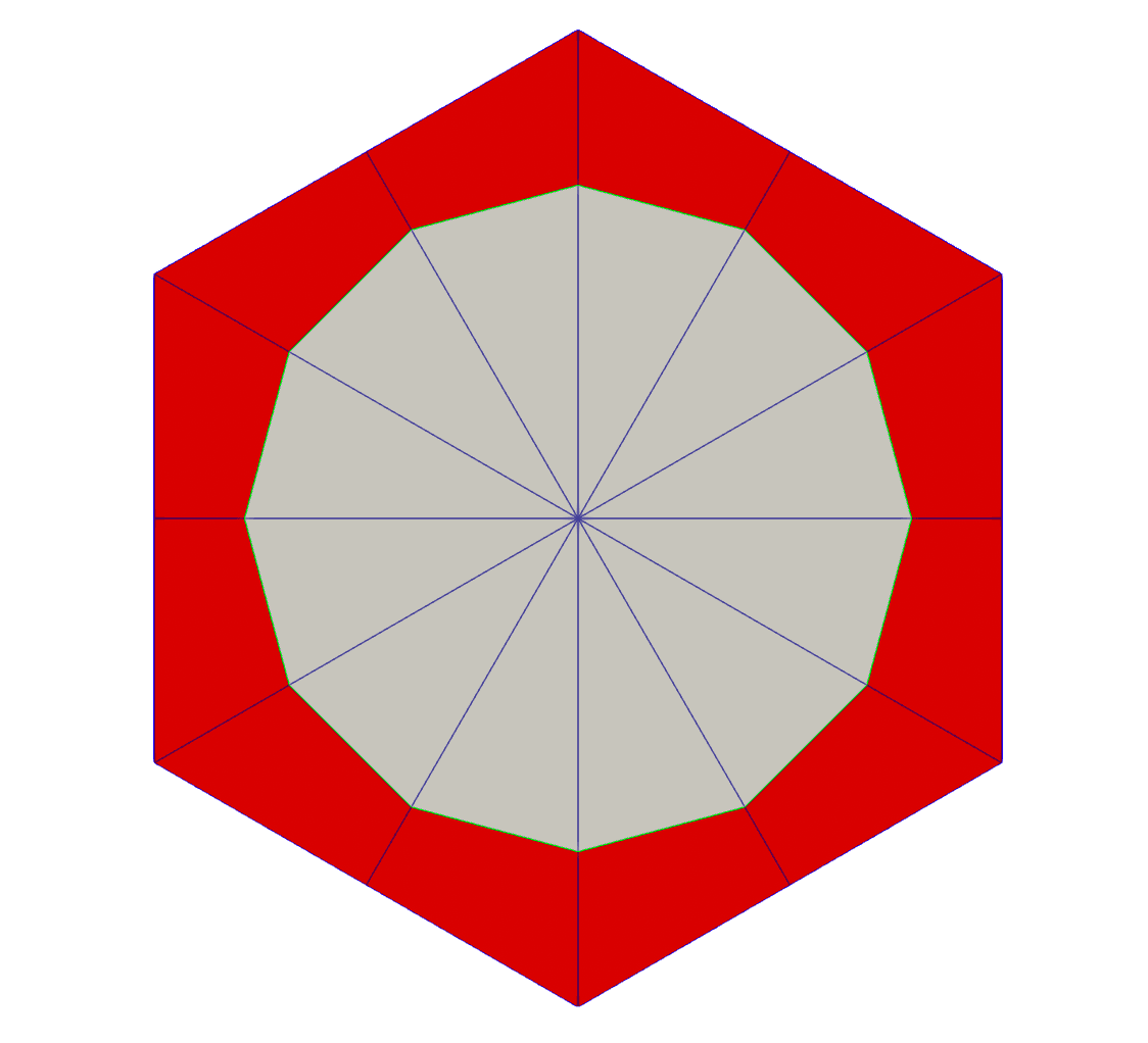
Figure 2: The 2D heat pipe pin cell mesh.
Two fake pin cell meshes are generated for the purpose of deletion in future steps.
  [fake_pin]
    type = PolygonConcentricCircleMeshGenerator
    num_sides = '6'
    flat_side_up = false
    num_sectors_per_side = '${pin_cell_sectors_per_side}'
    polygon_size = '${cell_apothem}'
    background_block_ids = '${to_remove_tri_block_id}'
    background_block_names = '${to_remove_tri_block_name}'
  []
  # We also delete this one, but delete it separately so we can generate a cohesive boundary for meshing
  [fake_pin_2]
    type = PolygonConcentricCircleMeshGenerator
    num_sides = '6'
    flat_side_up = false
    num_sectors_per_side = '${pin_cell_sectors_per_side}'
    polygon_size = '${cell_apothem}'
    background_block_ids = '${to_remove2_tri_block_id}'
    background_block_names = '${to_remove2_tri_block_name}'
  []
  #
  # Assembly type 1 R0
#Fuel Assembly
Fuel Pin assemblies are then generated for each of the 5 fuel pin meshes.
The fuel pin cell assembly is generated using the previous step's pin cell meshes. The fake pin cells are then deleted from the assembly mesh in order to create a void for the heat pipe meshes in future steps. The outer assembly boundary is generated. Boundary ids are renamed and meta data is added back to the assembly mesh. This process is repeated for the four other fuel assemblies.
When the hexagonal meshes are modified, they lose the original metadata. Thus reapplying the metadata from before the modifications is necessary to generate the assemblies. This will no longer be necessary in future versions.
  [assembly1_R0]
    type = PatternedHexMeshGenerator
    inputs = 'fake_pin fuel_pin_R0 heat_pipe_pin'
    rotate_angle = 0
    pattern_boundary = none
    pattern = '   0 1 1 0;
                 1 1 2 1 1;
                1 2 1 1 2 1;
               0 1 1 2 1 1 0;
                1 2 1 1 2 1;
                 1 1 2 1 1;
                  0 1 1 0'
    id_name = 'pin_id'
  []
  # delete fake cell
  [assembly1_R0_del]
    type = BlockDeletionGenerator
    input = assembly1_R0
    block = '${to_remove_tri_block_id}'
    #new_boundary = 'inner_bdy'
  []
  [assembly1_R0_outer_hex]
    type = HexagonConcentricCircleAdaptiveBoundaryMeshGenerator
    hexagon_size_style = apothem
    hexagon_size = '${asm_apothem}'
    # Re-use pin_cell_sectors_per_side, the number of sectors will be overridden by automatic refinement by the subsequent XYDG
    num_sectors_per_side = '${pin_cell_sectors_per_side}'
    background_block_ids = '${monolith_tri_block_id}'
    background_block_names = '${monolith_tri_block_name}'
  []
  # add background meshes of hex assembly and merge with hex cells
  [hex_assembly1_R0]
    type = XYDelaunayGenerator
    boundary = 'assembly1_R0_outer_hex'
    holes = 'assembly1_R0_del'
    stitch_holes = 'true'
    refine_holes = 'false'
    add_nodes_per_boundary_segment = ${hex_assembly_xydg_nodes_to_add}
    output_boundary = 10000
    # Get a bunch of errors if this is set to 'true'
    refine_boundary = false
    desired_area = 0.4
    smooth_triangulation = true
  []
  [hex_assembly1_R0_rename_boundary_id]
    type = RenameBoundaryGenerator
    input = hex_assembly1_R0
    old_boundary = '1'
    new_boundary = '11'
  []
  [hex_assembly1_R0_meta]
    type = AddMetaDataGenerator
    input = hex_assembly1_R0_rename_boundary_id
  []
  #
  # Assembly type 1 R1
  #
  [assembly1_R1]
    type = PatternedHexMeshGenerator
    inputs = 'fake_pin fuel_pin_R1 heat_pipe_pin'
    rotate_angle = 0
    pattern_boundary = none
    pattern = '   0 1 1 0;
                 1 1 2 1 1;
                1 2 1 1 2 1;
               0 1 1 2 1 1 0;
                1 2 1 1 2 1;
                 1 1 2 1 1;
                  0 1 1 0'
    id_name = 'pin_id'
  []
  # delete fake cell
  [assembly1_R1_del]
    type = BlockDeletionGenerator
    input = assembly1_R1
    block = '${to_remove_tri_block_id}'
  []
  [assembly1_R1_outer_hex]
    type = HexagonConcentricCircleAdaptiveBoundaryMeshGenerator
    hexagon_size_style = apothem
    hexagon_size = '${asm_apothem}'
    # Re-use pin_cell_sectors_per_side, the number of sectors will be overridden by automatic refinement by the subsequent XYDG
    num_sectors_per_side = '${pin_cell_sectors_per_side}'
    background_block_ids = '${monolith_tri_block_id}'
    background_block_names = '${monolith_tri_block_name}'
  []
  # add background meshes of hex assembly and merge with hex cells
  [hex_assembly1_R1]
    type = XYDelaunayGenerator
    boundary = 'assembly1_R1_outer_hex'
    holes = 'assembly1_R1_del'
    stitch_holes = 'true'
    refine_holes = 'false'
    add_nodes_per_boundary_segment = ${hex_assembly_xydg_nodes_to_add}
    output_boundary = 10000
    # Get a bunch of errors if this is set to 'true'
    refine_boundary = false
    desired_area = 0.4
    smooth_triangulation = true
  []
  [hex_assembly1_R1_rename_boundary_id]
    type = RenameBoundaryGenerator
    input = hex_assembly1_R1
    old_boundary = '1'
    new_boundary = '11'
  []
  [hex_assembly1_R1_meta]
    type = AddMetaDataGenerator
    input = hex_assembly1_R1_rename_boundary_id
  []
  #
  # Assembly type 1 R2
  #
  [assembly1_R2]
    type = PatternedHexMeshGenerator
    inputs = 'fake_pin fuel_pin_R2 heat_pipe_pin'
    rotate_angle = 0
    pattern_boundary = none
    pattern = '   0 1 1 0;
                 1 1 2 1 1;
                1 2 1 1 2 1;
               0 1 1 2 1 1 0;
                1 2 1 1 2 1;
                 1 1 2 1 1;
                  0 1 1 0'
    id_name = 'pin_id'
    #external_boundary_id = '${assembly1_boundary_id}'
    #external_boundary_name = '${assembly1_boundary_name}'
  []
  # delete fake cell
  [assembly1_R2_del]
    type = BlockDeletionGenerator
    input = assembly1_R2
    block = '${to_remove_tri_block_id}'
    #new_boundary = 'inner_bdy'
  []
  [assembly1_R2_outer_hex]
    type = HexagonConcentricCircleAdaptiveBoundaryMeshGenerator
    hexagon_size_style = apothem
    hexagon_size = '${asm_apothem}'
    # Re-use pin_cell_sectors_per_side, the number of sectors will be overridden by automatic refinement by the subsequent XYDG
    num_sectors_per_side = '${pin_cell_sectors_per_side}'
    background_block_ids = '${monolith_tri_block_id}'
    background_block_names = '${monolith_tri_block_name}'
  []
  # add background meshes of hex assembly and merge with hex cells
  [hex_assembly1_R2]
    type = XYDelaunayGenerator
    boundary = 'assembly1_R2_outer_hex'
    holes = 'assembly1_R2_del'
    stitch_holes = 'true'
    refine_holes = 'false'
    add_nodes_per_boundary_segment = ${hex_assembly_xydg_nodes_to_add}
    output_boundary = 10000
    # Get a bunch of errors if this is set to 'true'
    refine_boundary = false
    desired_area = 0.4
    smooth_triangulation = true
  []
  [hex_assembly1_R2_rename_boundary_id]
    type = RenameBoundaryGenerator
    input = hex_assembly1_R2
    old_boundary = '1'
    new_boundary = '11'
  []
  [hex_assembly1_R2_meta]
    type = AddMetaDataGenerator
    input = hex_assembly1_R2_rename_boundary_id
  []
  #
  # Assembly type 1 R3
  #
  [assembly1_R3]
    type = PatternedHexMeshGenerator
    inputs = 'fake_pin fuel_pin_R3 heat_pipe_pin'
    rotate_angle = 0
    pattern_boundary = none
    pattern = '   0 1 1 0;
                 1 1 2 1 1;
                1 2 1 1 2 1;
               0 1 1 2 1 1 0;
                1 2 1 1 2 1;
                 1 1 2 1 1;
                  0 1 1 0'
    id_name = 'pin_id'
    #external_boundary_id = '${assembly1_boundary_id}'
    #external_boundary_name = '${assembly1_boundary_name}'
  []
  # delete fake cell
  [assembly1_R3_del]
    type = BlockDeletionGenerator
    input = assembly1_R3
    block = '${to_remove_tri_block_id}'
    #new_boundary = 'inner_bdy'
  []
  [assembly1_R3_outer_hex]
    type = HexagonConcentricCircleAdaptiveBoundaryMeshGenerator
    hexagon_size_style = apothem
    hexagon_size = '${asm_apothem}'
    # Re-use pin_cell_sectors_per_side, the number of sectors will be overridden by automatic refinement by the subsequent XYDG
    num_sectors_per_side = '${pin_cell_sectors_per_side}'
    background_block_ids = '${monolith_tri_block_id}'
    background_block_names = '${monolith_tri_block_name}'
  []
  # add background meshes of hex assembly and merge with hex cells
  [hex_assembly1_R3]
    type = XYDelaunayGenerator
    boundary = 'assembly1_R3_outer_hex'
    holes = 'assembly1_R3_del'
    stitch_holes = 'true'
    refine_holes = 'false'
    add_nodes_per_boundary_segment = ${hex_assembly_xydg_nodes_to_add}
    output_boundary = 10000
    # Get a bunch of errors if this is set to 'true'
    refine_boundary = false
    desired_area = 0.4
    smooth_triangulation = true
  []
  [hex_assembly1_R3_rename_boundary_id]
    type = RenameBoundaryGenerator
    input = hex_assembly1_R3
    old_boundary = '1'
    new_boundary = '11'
  []
  [hex_assembly1_R3_meta]
    type = AddMetaDataGenerator
    input = hex_assembly1_R3_rename_boundary_id
  []
  #
  # Assembly type 3 (with CR hole)
  #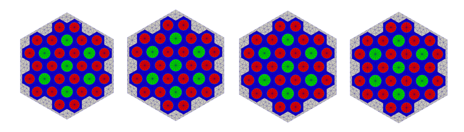
Figure 3: The identical 2D fuel assembly meshes; heat pipe pin cell meshes are in green and the fuel pin cell meshes are in red.
The last fuel pin assembly mesh generated includes a control rod channel. The same steps as above are followed, but block ids must be assigned to the larger, to be deleted, void region before being meshed. Then the control rod hole is carved and stitched back to the hexagonal assembly mesh.
  [assembly3]
    type = PatternedHexMeshGenerator
    inputs = 'fake_pin fuel3_pin heat_pipe_pin fake_pin_2'
    rotate_angle = 0
    pattern_boundary = none
    pattern = '0 1 1 0;
              1 1 2 1 1;
             1 2 3 3 2 1;
            0 1 3 3 3 1 0;
             1 2 3 3 2 1;
              1 1 2 1 1;
               0 1 1 0'
    id_name = 'pin_id'
    #external_boundary_id = '${assembly3_boundary_id}'
    #external_boundary_name = '${assembly3_boundary_name}'
  []
  [assmebly3_fake2_boundary]
    type = SideSetsAroundSubdomainGenerator
    block = ${to_remove2_tri_block_id}
    input = assembly3
    new_boundary = 867
  []
  # delete outer fake pin cells
  [assembly3_del_outer]
    type = BlockDeletionGenerator
    input = assmebly3_fake2_boundary
    block = '${to_remove_tri_block_id}'
    new_boundary = 53
  []
  # This creates a void of 7 pin cells in the center where fake_pin_2 was defined
  [assembly3_del_center]
    type = BlockDeletionGenerator
    input = assembly3_del_outer
    block = '${to_remove2_tri_block_id}'
    new_boundary = 76
  []
  # The deletion has created a void where the deleted pin cells were. We now assign a block ID to the deleted area
  [assembly3_rebuild_center]
    type = LowerDBlockFromSidesetGenerator
    input = assembly3_del_center
    sidesets = '76'
    new_block_id = '6123'
    new_block_name = 'rebuilt_center'
  []
  # Next we mesh the area with the new block ID, removing the void
  # In reality, we need to use XYDG to actually "mesh" this, this is just an intermediate step for using XYDG
  [assembly3_remesh_center]
    type = BlockToMeshConverterGenerator
    input = assembly3_rebuild_center
    target_blocks = 'rebuilt_center'
  []
  # Hole to carve using ParsedCurveGenerator
  [assembly3_carved_hole]
    type = ParsedCurveGenerator
    x_formula = '${hole_radius}*cos(t)'
    y_formula = 'y1:=${hole_radius}*sin(t);
                 y2:=${hole_radius}*sin(t);
                 if (t<${fparse pi},y1,y2)'
    section_bounding_t_values = '0.0 ${fparse pi} ${fparse 2.0*pi}'
    # 24 segments total around the hole can be refined based on the pin refinement
    nums_segments = '12 12'
    is_closed_loop = true
  []
  # Next we use XYDelaunayGenerator (XYDG) to carve the hole in the area of the pin cells we designated for the hole
  [assembly3_center_area_with_hole]
    type = XYDelaunayGenerator
    boundary = 'assembly3_remesh_center'
    holes = 'assembly3_carved_hole'
    hole_boundaries = 'center_hole_boundary'
    add_nodes_per_boundary_segment = 0
    output_boundary = 10010 # xy_output_boundary
    refine_boundary = false
    smooth_triangulation = true
    desired_area = 0.5
    output_subdomain_name = ${monolith_tri_block_id}
  []
  # Next we can stitch the area meshed by XYDG, which is the deleted pin cell area OUTSIDE of the hole, to the hex assembly mesh
  [assembly3_center_w_hole_void]
    type = StitchedMeshGenerator
    inputs = 'assembly3_del_center assembly3_center_area_with_hole'
    stitch_boundaries_pairs = '76 10010'
    prevent_boundary_ids_overlap = true
  []
  # Since we want the hole meshed we need to get the hole boundary and use XYDG to mesh it as well
  [assembly3_mesh_center_hole]
    type = XYDelaunayGenerator
    boundary = 'assembly3_center_w_hole_void'
    add_nodes_per_boundary_segment = 0
    input_boundary_names = center_hole_boundary # xy_output_boundary
    refine_boundary = false
    smooth_triangulation = true
    output_subdomain_name = ${rod_channel_block_id}
    output_boundary = to_be_stitched
    desired_area = 0.8
  []
  # Now we must stitch the meshed hole to the center area with the hole void
  [assembly3_center_stitched]
    type = StitchedMeshGenerator
    inputs = 'assembly3_center_w_hole_void assembly3_mesh_center_hole'
    stitch_boundaries_pairs = 'center_hole_boundary to_be_stitched'
    prevent_boundary_ids_overlap = true
  []
  [assembly3_outer_hex]
    type = HexagonConcentricCircleAdaptiveBoundaryMeshGenerator
    hexagon_size_style = apothem
    hexagon_size = '${asm_apothem}'
    # Re-use pin_cell_sectors_per_side, the number of sectors will be overridden by automatic refinement by the subsequent XYDG
    num_sectors_per_side = '${pin_cell_sectors_per_side}'
    background_block_ids = '${monolith_tri_block_id}'
    background_block_names = '${monolith_tri_block_name}'
  []
  # add background meshes of hex assembly and merge with hex cells
  [hex_assembly3]
    type = XYDelaunayGenerator
    boundary = 'assembly3_outer_hex'
    holes = 'assembly3_center_stitched'
    stitch_holes = 'true'
    refine_holes = 'false'
    add_nodes_per_boundary_segment = ${hex_assembly_xydg_nodes_to_add}
    output_boundary = 10000
    # Get a bunch of errors if this is set to 'true'
    refine_boundary = false
    desired_area = 0.4
    smooth_triangulation = true
  []
  [hex_assembly3_rename_boundary_id]
    type = RenameBoundaryGenerator
    input = hex_assembly3
    old_boundary = '1'
    new_boundary = '13'
  []
  [hex_assembly3_meta]
    type = AddMetaDataGenerator
    input = hex_assembly3_rename_boundary_id
  []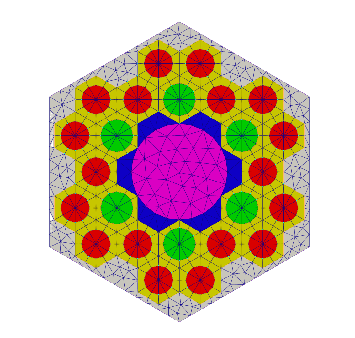
Figure 4: The 2D fuel assembly mesh containing a control rod channel in the center; heat pipe pin cell meshes are in green and the fuel pin cell meshes are in red.
Hexagonal Core Assembly
The hexagonal core assembly mesh is generated using the previous step's fuel pin assembly meshes. The block ids are renamed to separate the monolith triangular elements. Then the outer core ring boundary is created.
  [core1]
    type = PatternedHexMeshGenerator
    inputs = 'hex_assembly1_R0_meta hex_assembly1_R1_meta hex_assembly1_R2_meta hex_assembly1_R3_meta hex_assembly3_meta'
    rotate_angle = 30
    pattern_boundary = none
    pattern = '
          3 2 2 2 2 2 3;
         2 1 1 1 1 1 1 2;
        2 1 0 0 0 0 0 1 2;
       2 1 0 4 0 0 4 0 1 2;
      2 1 0 0 0 4 0 0 0 1 2;
     2 1 0 0 4 0 0 4 0 0 1 2;
    3 1 0 4 0 0 4 0 0 4 0 1 3;
     2 1 0 0 4 0 0 4 0 0 1 2;
      2 1 0 0 0 4 0 0 0 1 2;
       2 1 0 4 0 0 4 0 1 2;
        2 1 0 0 0 0 0 1 2;
         2 1 1 1 1 1 1 2;
          3 2 2 2 2 2 3'
    id_name = 'assembly_id'
    external_boundary_id = '${core_boundary_id}'
    external_boundary_name = '${core_boundary_name}'
  []
  # separate monolith tri
  [rename_block_ids_mono]
    type = RenameBlockGenerator
    input = 'core1'
    old_block = '0'
    new_block = '${monolith_tri_block_id}'
  []
  # Use parsed curve because we will remesh it with XYDG
  [outer_core_ring]
    type = ParsedCurveGenerator
    x_formula = '${outer_core_radius}*cos(t)'
    y_formula = 'y1:=${outer_core_radius}*sin(t);
                 y2:=${outer_core_radius}*sin(t);
                 if (t<${fparse pi},y1,y2)'
    section_bounding_t_values = '0.0 ${fparse pi} ${fparse 2.0*pi}'
    nums_segments = '40 40'
    is_closed_loop = true
  []
  # Mesh control drums using PolygonConcentricCircleMeshGenerator
  # and then AzimuthalBlockSplitGenerator for part of the mesh
  # then use XYDG to merge the two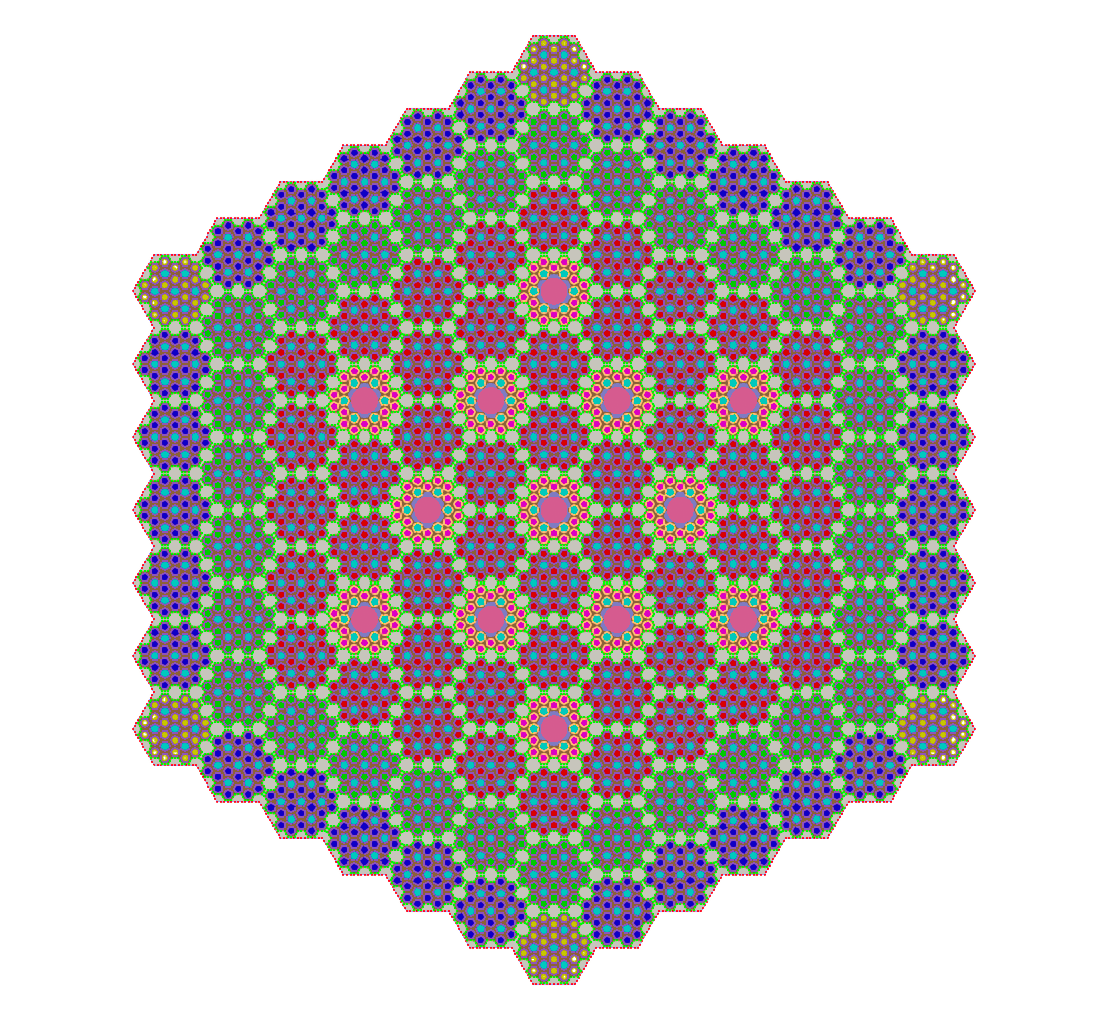
Figure 5: The 2D hexagonal core assembly mesh.
Control Drum Meshes
The meshes for the 12 control drums are then generated. The control drum base mesh is first generated, then the outer polygon area is deleted to keep only the circular control drum.
  [control_drum_base]
    type = PolygonConcentricCircleMeshGenerator
    num_sides = 6
    polygon_size = ${control_drum_polygon_apothem}
    polygon_size_style = apothem
    num_sectors_per_side = ${control_drum_num_sectors}
    background_intervals = 1
    background_block_ids = '${to_remove_quad_block_id}'
    background_block_names = '${to_remove_quad_block_name}'
    ring_radii = '${control_drum_inner_radius} ${control_drum_outer_radius}'
    ring_intervals = '1 2'
    ring_block_ids = '${drum_reflector_quad_block_id} ${drum_vary_block_id}'
    ring_block_names = '${drum_reflector_quad_block_name} ${drum_vary_block_name}'
    preserve_volumes = true
    quad_center_elements = true
    #is_control_drum = true
  []
  [control_drum_01]
    type = AzimuthalBlockSplitGenerator
    input = control_drum_base
    start_angle = 300
    angle_range = ${control_drum_absorber_angle}
    old_blocks = ${drum_vary_block_id}
    new_block_ids = ${drum_absorber_block_id}
    new_block_names = ${drum_absorber_block_name}
    preserve_volumes = true
  []
  # Delete outer polygon area, keeping only circles
  [control_drum_01_delete]
    type = BlockDeletionGenerator
    input = control_drum_01
    block = '${to_remove_quad_block_id}'
    new_boundary = ${drum_boundary_id}
[]The control drum mesh is rotated then translated multiple times to account for every position and placement of the drums in the core.
  [control_drum_S1_A]
    type = TransformGenerator
    input = control_drum_01_delete
    transform = TRANSLATE
    vector_value = '-${control_drum_x_coord} ${control_drum_y_coord} 0'
  []
  [control_drum_S1_B]
    type = TransformGenerator
    input = control_drum_01_delete
    transform = TRANSLATE
    vector_value = '-${control_drum_x_coord} -${control_drum_y_coord} 0'
  []
  # Rotate the control drum which is placed on another side
  [control_drum_S2]
    type = TransformGenerator
    input = control_drum_01_delete
    transform = ROTATE
    vector_value = '60 0 0'
  []
  [control_drum_S3]
    type = TransformGenerator
    input = control_drum_01_delete
    transform = ROTATE
    vector_value = '120 0 0'
  []
  [control_drum_S4]
    type = TransformGenerator
    input = control_drum_01_delete
    transform = ROTATE
    vector_value = '180 0 0'
  []
  [control_drum_S5]
    type = TransformGenerator
    input = control_drum_01_delete
    transform = ROTATE
    vector_value = '240 0 0'
  []
  [control_drum_S6]
    type = TransformGenerator
    input = control_drum_01_delete
    transform = ROTATE
    vector_value = '300 0 0'
  []
  [control_drum_S4_A]
    type = TransformGenerator
    input = control_drum_S4
    transform = TRANSLATE
    vector_value = '${control_drum_x_coord} ${control_drum_y_coord} 0'
  []
  [control_drum_S4_B]
    type = TransformGenerator
    input = control_drum_S4
    transform = TRANSLATE
    #vector_value = '120.1 -30.31 0'
    vector_value = '${control_drum_x_coord} -${control_drum_y_coord} 0'
  []
  [control_drum_S5_A]
    type = TransformGenerator
    input = control_drum_S5
    transform = TRANSLATE
    vector_value = '${control_drum_x_coord_s5_b} ${control_drum_y_coord_s5_b} 0'
  []
  [control_drum_S5_B]
    type = TransformGenerator
    input = control_drum_S5
    transform = TRANSLATE
    vector_value = '${control_drum_x_coord_s5_a} ${control_drum_y_coord_s5_a} 0'
  []
  [control_drum_S6_A]
    type = TransformGenerator
    input = control_drum_S6
    transform = TRANSLATE
    vector_value = '-${control_drum_x_coord_s5_a} ${control_drum_y_coord_s5_a} 0'
  []
  [control_drum_S6_B]
    type = TransformGenerator
    input = control_drum_S6
    transform = TRANSLATE
    vector_value = '-${control_drum_x_coord_s5_b} ${control_drum_y_coord_s5_b} 0'
  []
  [control_drum_S2_A]
    type = TransformGenerator
    input = control_drum_S2
    transform = TRANSLATE
    vector_value = '-${control_drum_x_coord_s5_b} -${control_drum_y_coord_s5_b} 0'
  []
  [control_drum_S2_B]
    type = TransformGenerator
    input = control_drum_S2
    transform = TRANSLATE
    vector_value = '-${control_drum_x_coord_s5_a} -${control_drum_y_coord_s5_a} 0'
  []
  [control_drum_S3_A]
    type = TransformGenerator
    input = control_drum_S3
    transform = TRANSLATE
    vector_value = '${control_drum_x_coord_s5_b} -${control_drum_y_coord_s5_b} 0'
  []
  [control_drum_S3_B]
    type = TransformGenerator
    input = control_drum_S3
    transform = TRANSLATE
    vector_value = '${control_drum_x_coord_s5_a} -${control_drum_y_coord_s5_a} 0'
  []
  # Polygons in the outer reflector region in an effort to reduce areas meshed by XYDG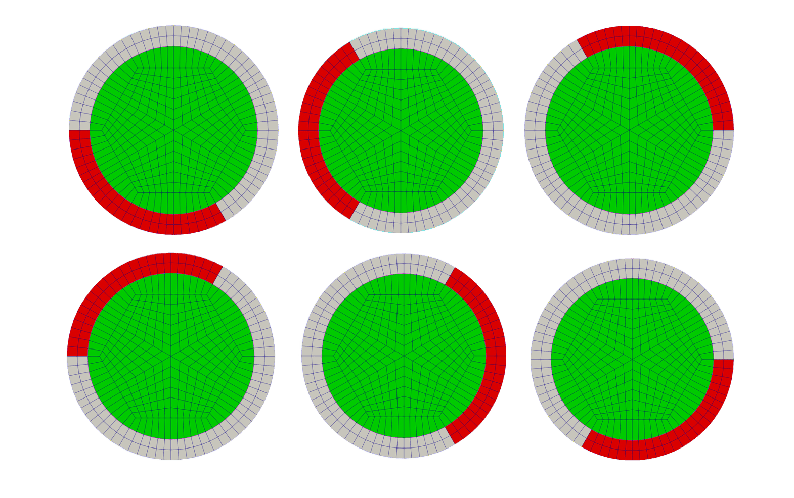
Figure 6: Six control rods with different orientations.
Reflector Mesh
The mesh for the reflector is generated using a lattice of polygonal meshes to keep a more structured mesh, and avoid generating a 2D mesh in a large area. The mesh is then translated several times to account for every position and placement of reflectors in the core.
  [reflector_polygon]
    type = PolygonConcentricCircleMeshGenerator
    num_sides = 6
    polygon_size = ${reflector_polygon_size}
    polygon_size_style = apothem
    num_sectors_per_side = ${reflector_polygon_num_sectors_per_side}
    ring_intervals = 1
    ring_radii = ${reflector_ring_radius}
    ring_block_ids = '${reflector_quad_block_id}'
    ring_block_names = '${reflector_quad_block_name}'
    background_intervals = 1
    background_block_ids = '${to_remove_quad_block_id}'
    background_block_names = '${to_remove_quad_block_name}'
    preserve_volumes = true
    quad_center_elements = true
    #is_control_drum = true
  []
  [reflector_polygon_delete]
    type = BlockDeletionGenerator
    input = reflector_polygon
    block = '${to_remove_quad_block_id}'
    new_boundary = ${drum_boundary_id}
  []
  [reflector_polygon_01]
    type = TransformGenerator
    input = reflector_polygon_delete
    transform = TRANSLATE
    vector_value = '${reflector_polygon_x_coord} 0 0'
  []
  [reflector_polygon_02]
    type = TransformGenerator
    input = reflector_polygon_delete
    transform = TRANSLATE
    vector_value = '${reflector_polygon_alt_x_coord} ${reflector_polygon_alt_y_coord} 0'
  []
  [reflector_polygon_04]
    type = TransformGenerator
    input = reflector_polygon_delete
    transform = TRANSLATE
    vector_value = '-${reflector_polygon_x_coord} 0 0'
  []
# add background meshes of hex assembly and merge with hex cellsOuter Core Mesh
Lastly, the core mesh is merged with the control drum and reflector meshes to generate a final core mesh which includes the outer core area. Block ids are renamed to keep triangular and quadrilateral elements separate. The outer vessel mesh is generated and sidesets are added to specify the radial boundary of the reactor vessel.
  [outer_core_mesh]
    type = XYDelaunayGenerator
    boundary = 'outer_core_ring'
    #holes = 'core1 control_drum_S1_A control_drum_S1_B control_drum_S4_A control_drum_S4_B control_drum_S5_A control_drum_S5_B control_drum_S6_A control_drum_S6_B control_drum_S2_A control_drum_S2_B control_drum_S3_A control_drum_S3_B'
    holes = 'rename_block_ids_mono control_drum_S1_A control_drum_S1_B control_drum_S4_A control_drum_S4_B control_drum_S5_A control_drum_S5_B control_drum_S6_A control_drum_S6_B control_drum_S2_A control_drum_S2_B control_drum_S3_A control_drum_S3_B'
    stitch_holes = 'true true true true true true true true true true true true true'
    refine_holes = 'false false false false false false false false false false false false false'
    #add_nodes_per_boundary_segment = 200
    output_boundary = 10002
    refine_boundary = true
    desired_area = 6.0
    smooth_triangulation = true
  []
  # separate reflector tri and quad
  [rename_block_ids_reflector]
    type = RenameBlockGenerator
    input = outer_core_mesh
    old_block = '0 ${drum_reflector_quad_block_id}'
    new_block = '${reflector_tri_block_id} ${reflector_quad_block_id}'
  []
  [outer_cannister]
    type = PeripheralTriangleMeshGenerator
    input = rename_block_ids_reflector
    peripheral_ring_radius = ${outer_cannister_radius}
    peripheral_ring_num_segments = 100
    desired_area = 10
    peripheral_ring_block_name = ${outer_cannister_block_name}
  []
  [sideset_gen]
    type = ParsedGenerateSideset
    input = outer_cannister
    combinatorial_geometry = 'x*x+y*y>146.5*146.5'
    new_sideset_name = 'radial_boundary'
  []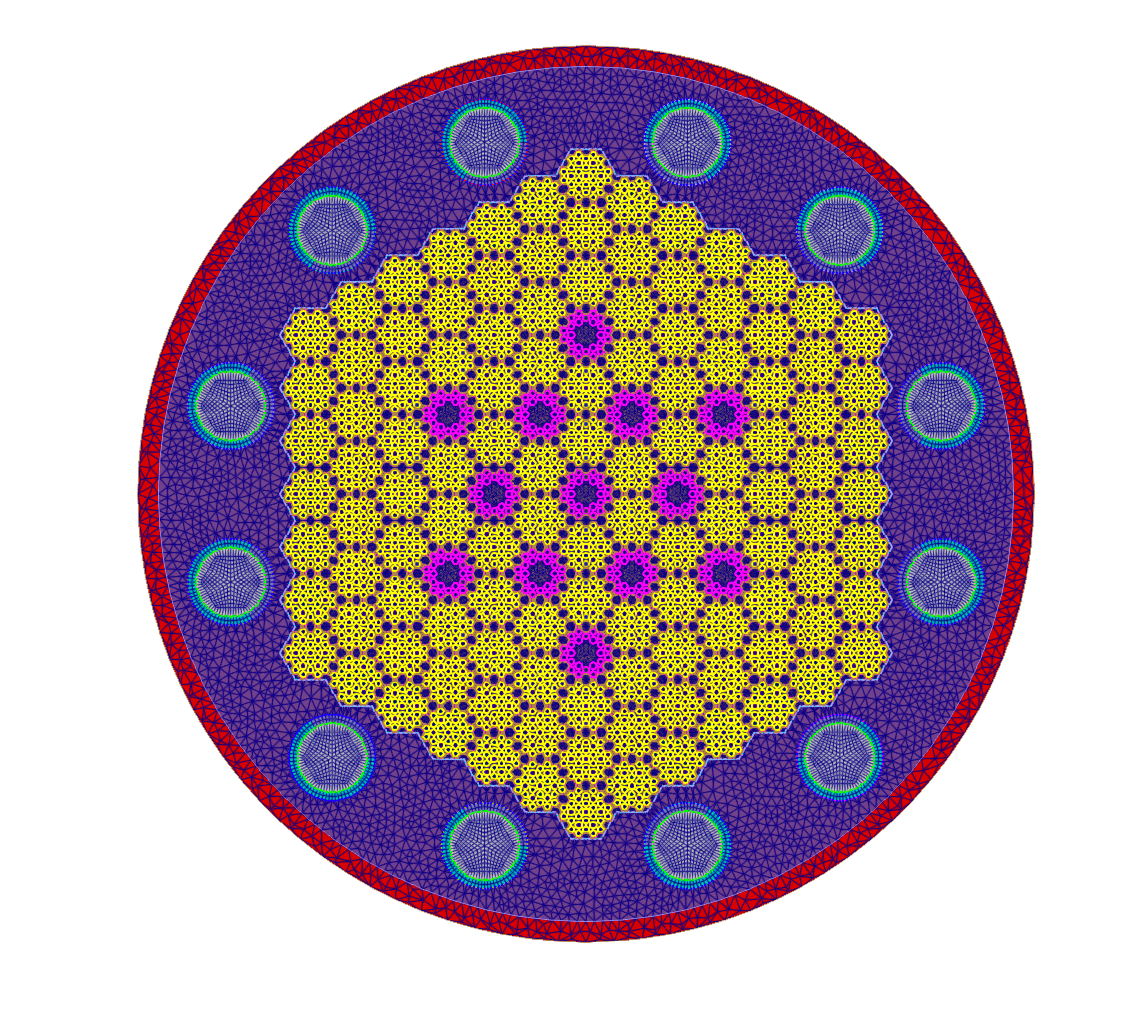
Figure 8: The 2D final core assembly mesh featuring 12 control drums, exterior reactor vessel ring in red, fuel assemblies in yellow, and fuel assemblies with control rod channels in pink.
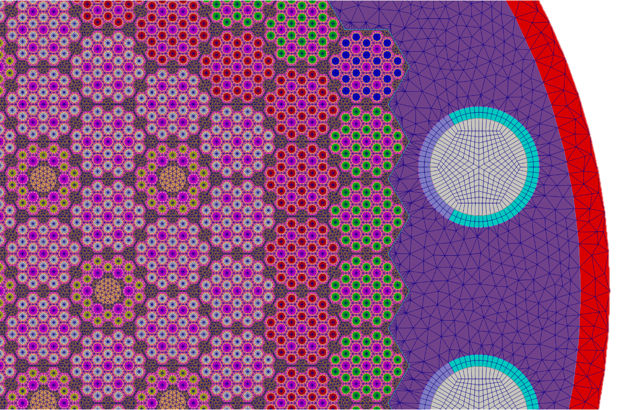
Figure 9: Closeup of the 2D final core assembly mesh featuring control drums in gray and fuel assemblies with and without control rod channels.
Extrusion to 3D Specifications
The spacial discretization specifications are summarized below.
Table 1: The 2D mesh can be extruded to form a 3D mesh. Table 1 summarizes the extrusion specifications in the gHPMR model, from Ortensi et al. (2024).
| Spacial Discretization | Value |
|---|---|
| Number of Axial Elements in Evaporator Section | 18 |
| Number of Axial Elements in Adiabatic Section | 4 |
| Number of Axial Elements in Condenser Section | 18 |
| Number of Radial Elements in Wick Region | 2 |
| Number of Radial Elements in Annular Gap Region | 2 |
| Number of Radial Elements in Cladding Region | 2 |
References
- Javier Ortensi, Mustafa K. Jaradat, Joshua Hansel, and Stefano Terlizzi.
The monolithic heat pipe microreactor reference plant model.
Technical Report INL/RPT-24-77914, Idaho National Laboratory, 4 2024.[BibTeX]
@techreport{gHPMR_main,
    author = "Ortensi, Javier and Jaradat, Mustafa K. and Hansel, Joshua and Terlizzi, Stefano",
    institution = "Idaho National Laboratory",
    title = "The Monolithic Heat Pipe Microreactor Reference Plant Model",
    year = "2024",
    month = "4",
    number = "INL/RPT-24-77914"
}
(microreactors/gHPMR/2D_gHPMR_Final.i)
# ###########################################################################
#   Created by: Javier Ortensi (INL), Olin Calvin (INL), Yinbin Miao (ANL), and Yeon Sang Jung (ANL)
#   Start Date: May 9, 2023
#   Revision Date: Jul 11, 2023
#   Version Number: 44
#   Project: Generic Micro Reactor Fuel Assembly Type 1- NRC support
#   Description: assembly with fuel compacts and heat pipe
#   Input units: cm
#   Mesh units: m
# ###########################################################################

# Abbreviations used:
# CR: Control rod
# TRI: Triangular elements
# QUAD: Quadrilateral elements
# XYDG: XYDelaunayGenerator

# Used for more easily calling pi in functions
#constant_names = 'pi'
#constant_expressions = '${fparse pi}'

# Overall reactor geometry parameters, changing these values will change the subsequent derived values.
# Ideally, the core can handle ANY changes to these parameters, but in reality there are lots of restrictions,
# such as some values needing to always be larger than others, such as assembly pitch ALWAYS being larger than pin cell pitch.
# Assembly pitch (flat-to-flat)
asm_pitch = 17.368
asm_apothem = '${fparse asm_pitch / 2}'
asm_side = '${fparse asm_pitch / sqrt(3)}'
# Pin cell pitch
cell_pitch = 2.782
# Radius of the control rod holes in the assemblies
# WARNING: Currently the control rod hole MUST fit within an area created by removing 7 pin cells from the center of the mesh.
# The resulting "maximum" size for the CR hold radius is thus 2 pin cell side lengths.
# In reality the maximum is slightly smaller than this because the mesh generators do not support any intersection of points
hole_radius = 3.212 # adjusted to conserve volume - nominal is 3.2 cm
fuel_pin_radius = 0.95
heat_pipe_radius = 1.07
# Number of pin cell ring intervals (radial intervals inside fuel pins, heat pipes, etc.)
# NOTE: when using only a single radial ring (with quad_center_elements=false) the elements of the ring are TRI.
# If MORE than one ring interval is specified, the innermost ring interval with be TRI and all other rings QUAD.
# This necessitates specifying a different block ID for the ring intervals as a single block ID cannot have both TRI and QUAD elements
num_cell_ring_intervals = 1
# Number of pin cell background intervals (radial intervals for the hexagonal background)
#num_cell_background_intervals = 1
# Radius of the reflector around the core which contains both the active core and the outer control rods
outer_core_radius = 140.07 # nominal 140.0 - adjusted to preserve volume
outer_cannister_radius = 146.85 # preserve volume
# Control drum outer radius
control_drum_outer_radius = 14.1
# Have to create an outer polygon around the central ring which we will later delete
control_drum_polygon_apothem = '${fparse control_drum_outer_radius + 1.0}'
# Thickness of the control material portion of the control drum
control_drum_thickness = 2.8
# The angle (in degrees) of the control drum portion which is made of absorber
control_drum_absorber_angle = 120
# Number of sectors per side per hexagonal pin cell
# These values cannot be less than 2
pin_cell_sectors_per_side = '2 2 2 2 2 2'
# The number of sides of the polygon used to generate the control drum
#control_drum_num_sides = 6
# The number of sectors per side of the polygon used to generate the control drum
control_drum_sectors_per_side = 12
# Number of control rod hole segments for the curve of the holes.
# NOTE: Two curves are generated to create the circle, each with this specified number of segments.
# So the number of segments of the entire circle is equal to double this number.
#control_rod_hole_num_segments = 12
# Control drum position specification
# In order to specify the center of the control drums, we first determine the position of the control drum
# in Quadrant I where the control drum on the same side of the hexagon is in Quadrant IV.
# It becomes relatively trivial to determine the y-axis coordinate of this control drum
# and then specify the x-axis based on the desired gap between the assemblies and the control drum.
# Once this position is determined, trigonometry can be used to determine the x-y coordinates of all other control drums.
# Coord runs
control_drum_y_coord = '${fparse asm_pitch * 1.66}'
# Doesn't run
#control_drum_y_coord = ${fparse asm_pitch * 1.66}
# Gap between the end of the assemblies and the outer radius of the control drum
control_drum_gap = 2.0
control_drum_x_coord = '${fparse (10 * asm_side) + control_drum_gap + control_drum_outer_radius}'
control_drum_hypotenuse = '${fparse sqrt(control_drum_x_coord^2 + control_drum_y_coord^2)}'
control_drum_angle = '${fparse atan(control_drum_y_coord / control_drum_x_coord)}'
control_drum_angle_s5_a = '${fparse (pi/3) + control_drum_angle}'
control_drum_angle_s5_b = '${fparse (pi/3) - control_drum_angle}'
control_drum_x_coord_s5_a = '${fparse control_drum_hypotenuse * cos(control_drum_angle_s5_a)}'
control_drum_y_coord_s5_a = '${fparse control_drum_hypotenuse * sin(control_drum_angle_s5_a)}'
control_drum_x_coord_s5_b = '${fparse control_drum_hypotenuse * cos(control_drum_angle_s5_b)}'
control_drum_y_coord_s5_b = '${fparse control_drum_hypotenuse * sin(control_drum_angle_s5_b)}'
#control_drum_x_coord = 120.1
#control_drum_y_coord = 30.31

hex_assembly_xydg_nodes_to_add = 5

# Reflector polygons
# XYDG can create a relatively fine mesh, especially compared to the active core assemblies.
# We can define some polygons in the outer reflector to impose some amount of regularity and coarsen the mesh somewhat.
reflector_polygon_size = 13.0
#reflector_polygon_num_sides = 6
reflector_polygon_num_sectors_per_side = '8 8 8 8 8 8'
reflector_ring_radius = '${fparse reflector_polygon_size - 1.0}'
reflector_polygon_x_coord = 120
reflector_polygon_alt_y_coord = '${fparse reflector_polygon_x_coord*sin(pi/3)}'
reflector_polygon_alt_x_coord = '${fparse reflector_polygon_x_coord*cos(pi/3)}'

cell_apothem = '${fparse cell_pitch / 2}'
#cell_side = ${fparse cell_pitch / sqrt(3)}
control_drum_inner_radius = '${fparse control_drum_outer_radius - control_drum_thickness}'
# Vector of size equal to control_drum_num_sides with control_drum_sectors_per_side specified for each side. The total number of sectors used to generate the circular control drum is control_drum_num_sides * control_drum_sectors_per_side
# Depending on the angles specified the sector boundaries can be moved
control_drum_num_sectors = '${control_drum_sectors_per_side} ${control_drum_sectors_per_side} ${control_drum_sectors_per_side} ${control_drum_sectors_per_side} ${control_drum_sectors_per_side} ${control_drum_sectors_per_side}'

# Define block IDs and block names
fuel_R0_tri_block_id = 100
fuel_R1_tri_block_id = 110
fuel_R2_tri_block_id = 120
fuel_R3_tri_block_id = 130
fuel3_tri_block_id = 300
# Put the element type in the block name in case there is a conflict between TRI and QUAD elements later
fuel_R0_tri_block_name = Fuel_R0
fuel_R1_tri_block_name = Fuel_R1
fuel_R2_tri_block_name = Fuel_R2
fuel_R3_tri_block_name = Fuel_R3
fuel3_tri_block_name = Fuel3_R0
# HP
heat_pipe_tri_block_id = 500
heat_pipe_tri_block_name = Heat_Pipe
# monolith
monolith_tri_block_id = 611
monolith_tri_block_name = Monolith_TRI
monolith_quad_block_id = 650
monolith_quad_block_name = Monolith_QUAD
# reflector
reflector_tri_block_id = 700
#reflector_tri_block_name = Reflector_TRI
reflector_quad_block_id = 750
reflector_quad_block_name = Reflector_QUAD
# drum ring
#ring_block_id = 800
#ring_block_name = Ring
# drum reflector
#drum_reflector_tri_block_id = 850
#drum_reflector_tri_block_name = Drum_Reflector_TRI
drum_reflector_quad_block_id = 860
drum_reflector_quad_block_name = Drum_Reflector_QUAD
# Vary corresponds to the region where the absorber exists and can rotate to change position with reflector
drum_vary_block_id = 603
drum_vary_block_name = Drum_Vary
drum_absorber_block_id = 604
drum_absorber_block_name = Drum_Absorber
rod_channel_block_id = 705
# outer cannister
# outer_cannister_block_id = 715
outer_cannister_block_name = SS316

# If these block IDs/names are on the output mesh there is a problem
to_remove_tri_block_id = 1001
to_remove_tri_block_name = Remove_TRI
to_remove2_tri_block_id = 1002
to_remove2_tri_block_name = Remove2_TRI
to_remove_quad_block_id = 1011
to_remove_quad_block_name = Remove_QUAD

# Define boundary IDs/names
#fuel_cell_boundary_id = 101
#fuel_cell_boundary_name = Fuel_Cell_Boundary
#assembly1_boundary_id = 1001
#assembly1_boundary_name = Assembly1_Boundary
#hex_assembly_1_boundary_id = 1002
#hex_assembly_1_boundary_name = HexAssembly1_Boundary
#assembly2_boundary_id = 2001
#assembly2_boundary_name = Assembly2_Boundary
#assembly3_boundary_id = 3001
#assembly3_boundary_name = Assembly3_Boundary

core_boundary_id = 4001
core_boundary_name = Core_Boundary
#ring_boundary_id = 4002
#ring_boundary_name = Ring_Boundary
drum_boundary_id = 4003
#drum_boundary_name = Drum_Boundary

#
# Axial mesh extrusion
# NOTE: Not currently in use. Add an AdvancedExtruderGenerator for this
#
#heights = '20.0 20.0 120.0 20.0 20.0'
#subdivisions = ' 4     4   24    4    4  ' # 5 cm - 40 axial
#subdivisions = ' 2     2   12    2    2  ' # 10 cm - 20 axial
#layers = ' 0     1    2    3    4  '
output_file_base = gHPMR_2d_core

# old_ids = '${fuel_R0_tri_block_id} ${fuel_R1_tri_block_id} ${fuel_R2_tri_block_id} ${fuel_R3_tri_block_id} ${fuel3_tri_block_id} ${heat_pipe_tri_block_id} ${monolith_tri_block_id} ${reflector_tri_block_id} ${rod_channel_block_id} ${monolith_quad_block_id} ${reflector_quad_block_id} ${drum_absorber_block_id} ${drum_vary_block_id}' - 'unused parameter'
# new_ids_lv0 = '       2710                    2710                  2710                       2710              2710                    2710                       2710                        2710                    2710                    2711                         2801                      2802                    2802' - 'unused parameter'
# new_ids_lv1 = '       2100                    2110                  2120                       2130              2300                    2500                       2600                        2730                    2705                    2601                         2801                      2803                    2802' - 'unused parameter'
# new_ids_lv2 = '       2101                    2111                  2121                       2131              2301                    2501                       2600                        2730                    2705                    2601                         2801                      2803                    2802' - 'unused parameter'
# new_ids_lv3 = '       2102                    2112                  2122                       2132              2302                    2502                       2600                        2730                    2705                    2601                         2801                      2803                    2802' - 'unused parameter'
# new_ids_lv4 = '       2720                    2720                  2720                       2720              2720                    2503                       2720                        2720                    2705                    2721                         2801                      2802                    2802' - 'unused parameter'

[GlobalParams]
  # These metadata values are required by PatternedHexMeshGenerator
  # These values are used by the AddMetaDataGenerator
  real_scalar_metadata_names = 'pitch_meta pattern_pitch_meta max_radius_meta'
  # Pitch of the hexagonal fuel assembly including duct around assembly
  real_scalar_metadata_values = '${asm_pitch} ${asm_pitch} ${asm_pitch}'
  boolean_scalar_metadata_names = 'is_control_drum_meta'
  boolean_scalar_metadata_values = 'false'
  uint_vector_metadata_names = 'num_sectors_per_side_meta'
  uint_vector_metadata_values = '12 12 12 12 12 12'
  uint_scalar_metadata_names = 'background_intervals_meta'
  uint_scalar_metadata_values = '1'
  dof_id_type_scalar_metadata_names = 'node_id_background_meta'
  dof_id_type_scalar_metadata_values = '${monolith_tri_block_id}'
[]

[Mesh]
  # Define the hexagonal pin cell meshes
  [fuel_pin_R0]
    type = PolygonConcentricCircleMeshGenerator
    num_sides = 6
    flat_side_up = false
    num_sectors_per_side = '${pin_cell_sectors_per_side}'
    polygon_size = '${cell_apothem}'
    ring_radii = '${fuel_pin_radius}'
    ring_intervals = '${num_cell_ring_intervals}'
    ring_block_ids = '${fuel_R0_tri_block_id}'
    ring_block_names = '${fuel_R0_tri_block_name}'
    background_intervals = 1
    background_block_ids = '${monolith_quad_block_id}'
    background_block_names = '${monolith_quad_block_name}'
    preserve_volumes = on
  []
  [fuel_pin_R1]
    type = PolygonConcentricCircleMeshGenerator
    num_sides = 6
    flat_side_up = false
    num_sectors_per_side = '${pin_cell_sectors_per_side}'
    polygon_size = '${cell_apothem}'
    ring_radii = '${fuel_pin_radius}'
    ring_intervals = '${num_cell_ring_intervals}'
    ring_block_ids = '${fuel_R1_tri_block_id}'
    ring_block_names = '${fuel_R1_tri_block_name}'
    background_intervals = 1
    background_block_ids = '${monolith_quad_block_id}'
    background_block_names = '${monolith_quad_block_name}'
    preserve_volumes = on
  []
  [fuel_pin_R2]
    type = PolygonConcentricCircleMeshGenerator
    num_sides = 6
    flat_side_up = false
    num_sectors_per_side = '${pin_cell_sectors_per_side}'
    polygon_size = '${cell_apothem}'
    ring_radii = '${fuel_pin_radius}'
    ring_intervals = '${num_cell_ring_intervals}'
    ring_block_ids = '${fuel_R2_tri_block_id}'
    ring_block_names = '${fuel_R2_tri_block_name}'
    background_intervals = 1
    background_block_ids = '${monolith_quad_block_id}'
    background_block_names = '${monolith_quad_block_name}'
    preserve_volumes = on
  []
  [fuel_pin_R3]
    type = PolygonConcentricCircleMeshGenerator
    num_sides = 6
    flat_side_up = false
    num_sectors_per_side = '${pin_cell_sectors_per_side}'
    polygon_size = '${cell_apothem}'
    ring_radii = '${fuel_pin_radius}'
    ring_intervals = '${num_cell_ring_intervals}'
    ring_block_ids = '${fuel_R3_tri_block_id}'
    ring_block_names = '${fuel_R3_tri_block_name}'
    background_intervals = 1
    background_block_ids = '${monolith_quad_block_id}'
    background_block_names = '${monolith_quad_block_name}'
    preserve_volumes = on
  []
  [fuel3_pin]
    type = PolygonConcentricCircleMeshGenerator
    num_sides = 6
    flat_side_up = false
    num_sectors_per_side = '${pin_cell_sectors_per_side}'
    polygon_size = '${cell_apothem}'
    ring_radii = '${fuel_pin_radius}'
    ring_intervals = '${num_cell_ring_intervals}'
    ring_block_ids = '${fuel3_tri_block_id}'
    ring_block_names = '${fuel3_tri_block_name}'
    background_intervals = 1
    background_block_ids = '${monolith_quad_block_id}'
    background_block_names = '${monolith_quad_block_name}'
    preserve_volumes = on
  []
  # Call it a pin so we know it is a pin cell
  [heat_pipe_pin]
    type = PolygonConcentricCircleMeshGenerator
    num_sides = 6
    flat_side_up = false
    num_sectors_per_side = '${pin_cell_sectors_per_side}'
    polygon_size = '${cell_apothem}'
    ring_radii = '${heat_pipe_radius}'
    ring_intervals = '${num_cell_ring_intervals}'
    ring_block_ids = '${heat_pipe_tri_block_id}'
    ring_block_names = '${heat_pipe_tri_block_name}'
    background_intervals = 1
    background_block_ids = '${monolith_quad_block_id}'
    background_block_names = '${monolith_quad_block_name}'
    preserve_volumes = on
  []
  # Fake pin which we delete later
  [fake_pin]
    type = PolygonConcentricCircleMeshGenerator
    num_sides = '6'
    flat_side_up = false
    num_sectors_per_side = '${pin_cell_sectors_per_side}'
    polygon_size = '${cell_apothem}'
    background_block_ids = '${to_remove_tri_block_id}'
    background_block_names = '${to_remove_tri_block_name}'
  []
  # We also delete this one, but delete it separately so we can generate a cohesive boundary for meshing
  [fake_pin_2]
    type = PolygonConcentricCircleMeshGenerator
    num_sides = '6'
    flat_side_up = false
    num_sectors_per_side = '${pin_cell_sectors_per_side}'
    polygon_size = '${cell_apothem}'
    background_block_ids = '${to_remove2_tri_block_id}'
    background_block_names = '${to_remove2_tri_block_name}'
  []
  #
  # Assembly type 1 R0
  #
  [assembly1_R0]
    type = PatternedHexMeshGenerator
    inputs = 'fake_pin fuel_pin_R0 heat_pipe_pin'
    rotate_angle = 0
    pattern_boundary = none
    pattern = '   0 1 1 0;
                 1 1 2 1 1;
                1 2 1 1 2 1;
               0 1 1 2 1 1 0;
                1 2 1 1 2 1;
                 1 1 2 1 1;
                  0 1 1 0'
    id_name = 'pin_id'
  []
  # delete fake cell
  [assembly1_R0_del]
    type = BlockDeletionGenerator
    input = assembly1_R0
    block = '${to_remove_tri_block_id}'
    #new_boundary = 'inner_bdy'
  []
  [assembly1_R0_outer_hex]
    type = HexagonConcentricCircleAdaptiveBoundaryMeshGenerator
    hexagon_size_style = apothem
    hexagon_size = '${asm_apothem}'
    # Re-use pin_cell_sectors_per_side, the number of sectors will be overridden by automatic refinement by the subsequent XYDG
    num_sectors_per_side = '${pin_cell_sectors_per_side}'
    background_block_ids = '${monolith_tri_block_id}'
    background_block_names = '${monolith_tri_block_name}'
  []
  # add background meshes of hex assembly and merge with hex cells
  [hex_assembly1_R0]
    type = XYDelaunayGenerator
    boundary = 'assembly1_R0_outer_hex'
    holes = 'assembly1_R0_del'
    stitch_holes = 'true'
    refine_holes = 'false'
    add_nodes_per_boundary_segment = ${hex_assembly_xydg_nodes_to_add}
    output_boundary = 10000
    # Get a bunch of errors if this is set to 'true'
    refine_boundary = false
    desired_area = 0.4
    smooth_triangulation = true
  []
  [hex_assembly1_R0_rename_boundary_id]
    type = RenameBoundaryGenerator
    input = hex_assembly1_R0
    old_boundary = '1'
    new_boundary = '11'
  []
  [hex_assembly1_R0_meta]
    type = AddMetaDataGenerator
    input = hex_assembly1_R0_rename_boundary_id
  []
  #
  # Assembly type 1 R1
  #
  [assembly1_R1]
    type = PatternedHexMeshGenerator
    inputs = 'fake_pin fuel_pin_R1 heat_pipe_pin'
    rotate_angle = 0
    pattern_boundary = none
    pattern = '   0 1 1 0;
                 1 1 2 1 1;
                1 2 1 1 2 1;
               0 1 1 2 1 1 0;
                1 2 1 1 2 1;
                 1 1 2 1 1;
                  0 1 1 0'
    id_name = 'pin_id'
  []
  # delete fake cell
  [assembly1_R1_del]
    type = BlockDeletionGenerator
    input = assembly1_R1
    block = '${to_remove_tri_block_id}'
  []
  [assembly1_R1_outer_hex]
    type = HexagonConcentricCircleAdaptiveBoundaryMeshGenerator
    hexagon_size_style = apothem
    hexagon_size = '${asm_apothem}'
    # Re-use pin_cell_sectors_per_side, the number of sectors will be overridden by automatic refinement by the subsequent XYDG
    num_sectors_per_side = '${pin_cell_sectors_per_side}'
    background_block_ids = '${monolith_tri_block_id}'
    background_block_names = '${monolith_tri_block_name}'
  []
  # add background meshes of hex assembly and merge with hex cells
  [hex_assembly1_R1]
    type = XYDelaunayGenerator
    boundary = 'assembly1_R1_outer_hex'
    holes = 'assembly1_R1_del'
    stitch_holes = 'true'
    refine_holes = 'false'
    add_nodes_per_boundary_segment = ${hex_assembly_xydg_nodes_to_add}
    output_boundary = 10000
    # Get a bunch of errors if this is set to 'true'
    refine_boundary = false
    desired_area = 0.4
    smooth_triangulation = true
  []
  [hex_assembly1_R1_rename_boundary_id]
    type = RenameBoundaryGenerator
    input = hex_assembly1_R1
    old_boundary = '1'
    new_boundary = '11'
  []
  [hex_assembly1_R1_meta]
    type = AddMetaDataGenerator
    input = hex_assembly1_R1_rename_boundary_id
  []
  #
  # Assembly type 1 R2
  #
  [assembly1_R2]
    type = PatternedHexMeshGenerator
    inputs = 'fake_pin fuel_pin_R2 heat_pipe_pin'
    rotate_angle = 0
    pattern_boundary = none
    pattern = '   0 1 1 0;
                 1 1 2 1 1;
                1 2 1 1 2 1;
               0 1 1 2 1 1 0;
                1 2 1 1 2 1;
                 1 1 2 1 1;
                  0 1 1 0'
    id_name = 'pin_id'
    #external_boundary_id = '${assembly1_boundary_id}'
    #external_boundary_name = '${assembly1_boundary_name}'
  []
  # delete fake cell
  [assembly1_R2_del]
    type = BlockDeletionGenerator
    input = assembly1_R2
    block = '${to_remove_tri_block_id}'
    #new_boundary = 'inner_bdy'
  []
  [assembly1_R2_outer_hex]
    type = HexagonConcentricCircleAdaptiveBoundaryMeshGenerator
    hexagon_size_style = apothem
    hexagon_size = '${asm_apothem}'
    # Re-use pin_cell_sectors_per_side, the number of sectors will be overridden by automatic refinement by the subsequent XYDG
    num_sectors_per_side = '${pin_cell_sectors_per_side}'
    background_block_ids = '${monolith_tri_block_id}'
    background_block_names = '${monolith_tri_block_name}'
  []
  # add background meshes of hex assembly and merge with hex cells
  [hex_assembly1_R2]
    type = XYDelaunayGenerator
    boundary = 'assembly1_R2_outer_hex'
    holes = 'assembly1_R2_del'
    stitch_holes = 'true'
    refine_holes = 'false'
    add_nodes_per_boundary_segment = ${hex_assembly_xydg_nodes_to_add}
    output_boundary = 10000
    # Get a bunch of errors if this is set to 'true'
    refine_boundary = false
    desired_area = 0.4
    smooth_triangulation = true
  []
  [hex_assembly1_R2_rename_boundary_id]
    type = RenameBoundaryGenerator
    input = hex_assembly1_R2
    old_boundary = '1'
    new_boundary = '11'
  []
  [hex_assembly1_R2_meta]
    type = AddMetaDataGenerator
    input = hex_assembly1_R2_rename_boundary_id
  []
  #
  # Assembly type 1 R3
  #
  [assembly1_R3]
    type = PatternedHexMeshGenerator
    inputs = 'fake_pin fuel_pin_R3 heat_pipe_pin'
    rotate_angle = 0
    pattern_boundary = none
    pattern = '   0 1 1 0;
                 1 1 2 1 1;
                1 2 1 1 2 1;
               0 1 1 2 1 1 0;
                1 2 1 1 2 1;
                 1 1 2 1 1;
                  0 1 1 0'
    id_name = 'pin_id'
    #external_boundary_id = '${assembly1_boundary_id}'
    #external_boundary_name = '${assembly1_boundary_name}'
  []
  # delete fake cell
  [assembly1_R3_del]
    type = BlockDeletionGenerator
    input = assembly1_R3
    block = '${to_remove_tri_block_id}'
    #new_boundary = 'inner_bdy'
  []
  [assembly1_R3_outer_hex]
    type = HexagonConcentricCircleAdaptiveBoundaryMeshGenerator
    hexagon_size_style = apothem
    hexagon_size = '${asm_apothem}'
    # Re-use pin_cell_sectors_per_side, the number of sectors will be overridden by automatic refinement by the subsequent XYDG
    num_sectors_per_side = '${pin_cell_sectors_per_side}'
    background_block_ids = '${monolith_tri_block_id}'
    background_block_names = '${monolith_tri_block_name}'
  []
  # add background meshes of hex assembly and merge with hex cells
  [hex_assembly1_R3]
    type = XYDelaunayGenerator
    boundary = 'assembly1_R3_outer_hex'
    holes = 'assembly1_R3_del'
    stitch_holes = 'true'
    refine_holes = 'false'
    add_nodes_per_boundary_segment = ${hex_assembly_xydg_nodes_to_add}
    output_boundary = 10000
    # Get a bunch of errors if this is set to 'true'
    refine_boundary = false
    desired_area = 0.4
    smooth_triangulation = true
  []
  [hex_assembly1_R3_rename_boundary_id]
    type = RenameBoundaryGenerator
    input = hex_assembly1_R3
    old_boundary = '1'
    new_boundary = '11'
  []
  [hex_assembly1_R3_meta]
    type = AddMetaDataGenerator
    input = hex_assembly1_R3_rename_boundary_id
  []
  #
  # Assembly type 3 (with CR hole)
  #
  [assembly3]
    type = PatternedHexMeshGenerator
    inputs = 'fake_pin fuel3_pin heat_pipe_pin fake_pin_2'
    rotate_angle = 0
    pattern_boundary = none
    pattern = '0 1 1 0;
              1 1 2 1 1;
             1 2 3 3 2 1;
            0 1 3 3 3 1 0;
             1 2 3 3 2 1;
              1 1 2 1 1;
               0 1 1 0'
    id_name = 'pin_id'
    #external_boundary_id = '${assembly3_boundary_id}'
    #external_boundary_name = '${assembly3_boundary_name}'
  []
  [assmebly3_fake2_boundary]
    type = SideSetsAroundSubdomainGenerator
    block = ${to_remove2_tri_block_id}
    input = assembly3
    new_boundary = 867
  []
  # delete outer fake pin cells
  [assembly3_del_outer]
    type = BlockDeletionGenerator
    input = assmebly3_fake2_boundary
    block = '${to_remove_tri_block_id}'
    new_boundary = 53
  []
  # This creates a void of 7 pin cells in the center where fake_pin_2 was defined
  [assembly3_del_center]
    type = BlockDeletionGenerator
    input = assembly3_del_outer
    block = '${to_remove2_tri_block_id}'
    new_boundary = 76
  []
  # The deletion has created a void where the deleted pin cells were. We now assign a block ID to the deleted area
  [assembly3_rebuild_center]
    type = LowerDBlockFromSidesetGenerator
    input = assembly3_del_center
    sidesets = '76'
    new_block_id = '6123'
    new_block_name = 'rebuilt_center'
  []
  # Next we mesh the area with the new block ID, removing the void
  # In reality, we need to use XYDG to actually "mesh" this, this is just an intermediate step for using XYDG
  [assembly3_remesh_center]
    type = BlockToMeshConverterGenerator
    input = assembly3_rebuild_center
    target_blocks = 'rebuilt_center'
  []
  # Hole to carve using ParsedCurveGenerator
  [assembly3_carved_hole]
    type = ParsedCurveGenerator
    x_formula = '${hole_radius}*cos(t)'
    y_formula = 'y1:=${hole_radius}*sin(t);
                 y2:=${hole_radius}*sin(t);
                 if (t<${fparse pi},y1,y2)'
    section_bounding_t_values = '0.0 ${fparse pi} ${fparse 2.0*pi}'
    # 24 segments total around the hole can be refined based on the pin refinement
    nums_segments = '12 12'
    is_closed_loop = true
  []
  # Next we use XYDelaunayGenerator (XYDG) to carve the hole in the area of the pin cells we designated for the hole
  [assembly3_center_area_with_hole]
    type = XYDelaunayGenerator
    boundary = 'assembly3_remesh_center'
    holes = 'assembly3_carved_hole'
    hole_boundaries = 'center_hole_boundary'
    add_nodes_per_boundary_segment = 0
    output_boundary = 10010 # xy_output_boundary
    refine_boundary = false
    smooth_triangulation = true
    desired_area = 0.5
    output_subdomain_name = ${monolith_tri_block_id}
  []
  # Next we can stitch the area meshed by XYDG, which is the deleted pin cell area OUTSIDE of the hole, to the hex assembly mesh
  [assembly3_center_w_hole_void]
    type = StitchedMeshGenerator
    inputs = 'assembly3_del_center assembly3_center_area_with_hole'
    stitch_boundaries_pairs = '76 10010'
    prevent_boundary_ids_overlap = true
  []
  # Since we want the hole meshed we need to get the hole boundary and use XYDG to mesh it as well
  [assembly3_mesh_center_hole]
    type = XYDelaunayGenerator
    boundary = 'assembly3_center_w_hole_void'
    add_nodes_per_boundary_segment = 0
    input_boundary_names = center_hole_boundary # xy_output_boundary
    refine_boundary = false
    smooth_triangulation = true
    output_subdomain_name = ${rod_channel_block_id}
    output_boundary = to_be_stitched
    desired_area = 0.8
  []
  # Now we must stitch the meshed hole to the center area with the hole void
  [assembly3_center_stitched]
    type = StitchedMeshGenerator
    inputs = 'assembly3_center_w_hole_void assembly3_mesh_center_hole'
    stitch_boundaries_pairs = 'center_hole_boundary to_be_stitched'
    prevent_boundary_ids_overlap = true
  []
  [assembly3_outer_hex]
    type = HexagonConcentricCircleAdaptiveBoundaryMeshGenerator
    hexagon_size_style = apothem
    hexagon_size = '${asm_apothem}'
    # Re-use pin_cell_sectors_per_side, the number of sectors will be overridden by automatic refinement by the subsequent XYDG
    num_sectors_per_side = '${pin_cell_sectors_per_side}'
    background_block_ids = '${monolith_tri_block_id}'
    background_block_names = '${monolith_tri_block_name}'
  []
  # add background meshes of hex assembly and merge with hex cells
  [hex_assembly3]
    type = XYDelaunayGenerator
    boundary = 'assembly3_outer_hex'
    holes = 'assembly3_center_stitched'
    stitch_holes = 'true'
    refine_holes = 'false'
    add_nodes_per_boundary_segment = ${hex_assembly_xydg_nodes_to_add}
    output_boundary = 10000
    # Get a bunch of errors if this is set to 'true'
    refine_boundary = false
    desired_area = 0.4
    smooth_triangulation = true
  []
  [hex_assembly3_rename_boundary_id]
    type = RenameBoundaryGenerator
    input = hex_assembly3
    old_boundary = '1'
    new_boundary = '13'
  []
  [hex_assembly3_meta]
    type = AddMetaDataGenerator
    input = hex_assembly3_rename_boundary_id
  []
  [core1]
    type = PatternedHexMeshGenerator
    inputs = 'hex_assembly1_R0_meta hex_assembly1_R1_meta hex_assembly1_R2_meta hex_assembly1_R3_meta hex_assembly3_meta'
    rotate_angle = 30
    pattern_boundary = none
    pattern = '
          3 2 2 2 2 2 3;
         2 1 1 1 1 1 1 2;
        2 1 0 0 0 0 0 1 2;
       2 1 0 4 0 0 4 0 1 2;
      2 1 0 0 0 4 0 0 0 1 2;
     2 1 0 0 4 0 0 4 0 0 1 2;
    3 1 0 4 0 0 4 0 0 4 0 1 3;
     2 1 0 0 4 0 0 4 0 0 1 2;
      2 1 0 0 0 4 0 0 0 1 2;
       2 1 0 4 0 0 4 0 1 2;
        2 1 0 0 0 0 0 1 2;
         2 1 1 1 1 1 1 2;
          3 2 2 2 2 2 3'
    id_name = 'assembly_id'
    external_boundary_id = '${core_boundary_id}'
    external_boundary_name = '${core_boundary_name}'
  []
  # separate monolith tri
  [rename_block_ids_mono]
    type = RenameBlockGenerator
    input = 'core1'
    old_block = '0'
    new_block = '${monolith_tri_block_id}'
  []
  # Use parsed curve because we will remesh it with XYDG
  [outer_core_ring]
    type = ParsedCurveGenerator
    x_formula = '${outer_core_radius}*cos(t)'
    y_formula = 'y1:=${outer_core_radius}*sin(t);
                 y2:=${outer_core_radius}*sin(t);
                 if (t<${fparse pi},y1,y2)'
    section_bounding_t_values = '0.0 ${fparse pi} ${fparse 2.0*pi}'
    nums_segments = '40 40'
    is_closed_loop = true
  []
  # Mesh control drums using PolygonConcentricCircleMeshGenerator
  # and then AzimuthalBlockSplitGenerator for part of the mesh
  # then use XYDG to merge the two
  [control_drum_base]
    type = PolygonConcentricCircleMeshGenerator
    num_sides = 6
    polygon_size = ${control_drum_polygon_apothem}
    polygon_size_style = apothem
    num_sectors_per_side = ${control_drum_num_sectors}
    background_intervals = 1
    background_block_ids = '${to_remove_quad_block_id}'
    background_block_names = '${to_remove_quad_block_name}'
    ring_radii = '${control_drum_inner_radius} ${control_drum_outer_radius}'
    ring_intervals = '1 2'
    ring_block_ids = '${drum_reflector_quad_block_id} ${drum_vary_block_id}'
    ring_block_names = '${drum_reflector_quad_block_name} ${drum_vary_block_name}'
    preserve_volumes = true
    quad_center_elements = true
    #is_control_drum = true
  []
  [control_drum_01]
    type = AzimuthalBlockSplitGenerator
    input = control_drum_base
    start_angle = 300
    angle_range = ${control_drum_absorber_angle}
    old_blocks = ${drum_vary_block_id}
    new_block_ids = ${drum_absorber_block_id}
    new_block_names = ${drum_absorber_block_name}
    preserve_volumes = true
  []
  # Delete outer polygon area, keeping only circles
  [control_drum_01_delete]
    type = BlockDeletionGenerator
    input = control_drum_01
    block = '${to_remove_quad_block_id}'
    new_boundary = ${drum_boundary_id}
  []
  [control_drum_S1_A]
    type = TransformGenerator
    input = control_drum_01_delete
    transform = TRANSLATE
    vector_value = '-${control_drum_x_coord} ${control_drum_y_coord} 0'
  []
  [control_drum_S1_B]
    type = TransformGenerator
    input = control_drum_01_delete
    transform = TRANSLATE
    vector_value = '-${control_drum_x_coord} -${control_drum_y_coord} 0'
  []
  # Rotate the control drum which is placed on another side
  [control_drum_S2]
    type = TransformGenerator
    input = control_drum_01_delete
    transform = ROTATE
    vector_value = '60 0 0'
  []
  [control_drum_S3]
    type = TransformGenerator
    input = control_drum_01_delete
    transform = ROTATE
    vector_value = '120 0 0'
  []
  [control_drum_S4]
    type = TransformGenerator
    input = control_drum_01_delete
    transform = ROTATE
    vector_value = '180 0 0'
  []
  [control_drum_S5]
    type = TransformGenerator
    input = control_drum_01_delete
    transform = ROTATE
    vector_value = '240 0 0'
  []
  [control_drum_S6]
    type = TransformGenerator
    input = control_drum_01_delete
    transform = ROTATE
    vector_value = '300 0 0'
  []
  [control_drum_S4_A]
    type = TransformGenerator
    input = control_drum_S4
    transform = TRANSLATE
    vector_value = '${control_drum_x_coord} ${control_drum_y_coord} 0'
  []
  [control_drum_S4_B]
    type = TransformGenerator
    input = control_drum_S4
    transform = TRANSLATE
    #vector_value = '120.1 -30.31 0'
    vector_value = '${control_drum_x_coord} -${control_drum_y_coord} 0'
  []
  [control_drum_S5_A]
    type = TransformGenerator
    input = control_drum_S5
    transform = TRANSLATE
    vector_value = '${control_drum_x_coord_s5_b} ${control_drum_y_coord_s5_b} 0'
  []
  [control_drum_S5_B]
    type = TransformGenerator
    input = control_drum_S5
    transform = TRANSLATE
    vector_value = '${control_drum_x_coord_s5_a} ${control_drum_y_coord_s5_a} 0'
  []
  [control_drum_S6_A]
    type = TransformGenerator
    input = control_drum_S6
    transform = TRANSLATE
    vector_value = '-${control_drum_x_coord_s5_a} ${control_drum_y_coord_s5_a} 0'
  []
  [control_drum_S6_B]
    type = TransformGenerator
    input = control_drum_S6
    transform = TRANSLATE
    vector_value = '-${control_drum_x_coord_s5_b} ${control_drum_y_coord_s5_b} 0'
  []
  [control_drum_S2_A]
    type = TransformGenerator
    input = control_drum_S2
    transform = TRANSLATE
    vector_value = '-${control_drum_x_coord_s5_b} -${control_drum_y_coord_s5_b} 0'
  []
  [control_drum_S2_B]
    type = TransformGenerator
    input = control_drum_S2
    transform = TRANSLATE
    vector_value = '-${control_drum_x_coord_s5_a} -${control_drum_y_coord_s5_a} 0'
  []
  [control_drum_S3_A]
    type = TransformGenerator
    input = control_drum_S3
    transform = TRANSLATE
    vector_value = '${control_drum_x_coord_s5_b} -${control_drum_y_coord_s5_b} 0'
  []
  [control_drum_S3_B]
    type = TransformGenerator
    input = control_drum_S3
    transform = TRANSLATE
    vector_value = '${control_drum_x_coord_s5_a} -${control_drum_y_coord_s5_a} 0'
  []
  # Polygons in the outer reflector region in an effort to reduce areas meshed by XYDG
  [reflector_polygon]
    type = PolygonConcentricCircleMeshGenerator
    num_sides = 6
    polygon_size = ${reflector_polygon_size}
    polygon_size_style = apothem
    num_sectors_per_side = ${reflector_polygon_num_sectors_per_side}
    ring_intervals = 1
    ring_radii = ${reflector_ring_radius}
    ring_block_ids = '${reflector_quad_block_id}'
    ring_block_names = '${reflector_quad_block_name}'
    background_intervals = 1
    background_block_ids = '${to_remove_quad_block_id}'
    background_block_names = '${to_remove_quad_block_name}'
    preserve_volumes = true
    quad_center_elements = true
    #is_control_drum = true
  []
  [reflector_polygon_delete]
    type = BlockDeletionGenerator
    input = reflector_polygon
    block = '${to_remove_quad_block_id}'
    new_boundary = ${drum_boundary_id}
  []
  [reflector_polygon_01]
    type = TransformGenerator
    input = reflector_polygon_delete
    transform = TRANSLATE
    vector_value = '${reflector_polygon_x_coord} 0 0'
  []
  [reflector_polygon_02]
    type = TransformGenerator
    input = reflector_polygon_delete
    transform = TRANSLATE
    vector_value = '${reflector_polygon_alt_x_coord} ${reflector_polygon_alt_y_coord} 0'
  []
  [reflector_polygon_04]
    type = TransformGenerator
    input = reflector_polygon_delete
    transform = TRANSLATE
    vector_value = '-${reflector_polygon_x_coord} 0 0'
  []
  # add background meshes of hex assembly and merge with hex cells
  [outer_core_mesh]
    type = XYDelaunayGenerator
    boundary = 'outer_core_ring'
    #holes = 'core1 control_drum_S1_A control_drum_S1_B control_drum_S4_A control_drum_S4_B control_drum_S5_A control_drum_S5_B control_drum_S6_A control_drum_S6_B control_drum_S2_A control_drum_S2_B control_drum_S3_A control_drum_S3_B'
    holes = 'rename_block_ids_mono control_drum_S1_A control_drum_S1_B control_drum_S4_A control_drum_S4_B control_drum_S5_A control_drum_S5_B control_drum_S6_A control_drum_S6_B control_drum_S2_A control_drum_S2_B control_drum_S3_A control_drum_S3_B'
    stitch_holes = 'true true true true true true true true true true true true true'
    refine_holes = 'false false false false false false false false false false false false false'
    #add_nodes_per_boundary_segment = 200
    output_boundary = 10002
    refine_boundary = true
    desired_area = 6.0
    smooth_triangulation = true
  []
  # separate reflector tri and quad
  [rename_block_ids_reflector]
    type = RenameBlockGenerator
    input = outer_core_mesh
    old_block = '0 ${drum_reflector_quad_block_id}'
    new_block = '${reflector_tri_block_id} ${reflector_quad_block_id}'
  []
  [outer_cannister]
    type = PeripheralTriangleMeshGenerator
    input = rename_block_ids_reflector
    peripheral_ring_radius = ${outer_cannister_radius}
    peripheral_ring_num_segments = 100
    desired_area = 10
    peripheral_ring_block_name = ${outer_cannister_block_name}
  []
  [sideset_gen]
    type = ParsedGenerateSideset
    input = outer_cannister
    combinatorial_geometry = 'x*x+y*y>146.5*146.5'
    new_sideset_name = 'radial_boundary'
  []
  final_generator = sideset_gen

  # Change final_generator to use this diagnostics
  [diag]
    type = MeshDiagnosticsGenerator
    input = outer_core_mesh
    examine_element_overlap = WARNING
    examine_element_types = WARNING
    examine_element_volumes = WARNING
    examine_non_conformality = WARNING
    examine_nonplanar_sides = INFO
    examine_sidesets_orientation = WARNING
    search_for_adaptivity_nonconformality = WARNING
    check_local_jacobian = WARNING
  []
[]

[Problem]
  kernel_coverage_check = false
  solve = false
[]

[Executioner]
  type = Steady
[]

[GlobalParams]
  execute_on = 'final'
[]

[Postprocessors]
  [Fuel1_R0]
    type = VolumePostprocessor
    block = '${fuel_R0_tri_block_name}'
  []
  [Fuel1_R1]
    type = VolumePostprocessor
    block = '${fuel_R1_tri_block_name}'
  []
  [Fuel1_R2]
    type = VolumePostprocessor
    block = '${fuel_R2_tri_block_name}'
  []
  [Fuel1_R3]
    type = VolumePostprocessor
    block = '${fuel_R3_tri_block_name}'
  []
  [Fuel3_R0]
    type = VolumePostprocessor
    block = '${fuel3_tri_block_name}'
  []
  [HP]
    type = VolumePostprocessor
    block = '${heat_pipe_tri_block_name}'
  []
  [Rod_channel]
    type = VolumePostprocessor
    block = '${rod_channel_block_id}'
  []
  [Monolith]
    type = VolumePostprocessor
    block = '${monolith_tri_block_name} ${monolith_quad_block_name}'
  []
  [Drum_abs]
    type = VolumePostprocessor
    block = '${drum_absorber_block_name}'
  []
  [Drum_graphite]
    type = VolumePostprocessor
    block = '${drum_vary_block_name}'
  []
[]

[Outputs]
  file_base = ${output_file_base}
  exodus = true
  csv = true
[]