High Temperature Engineering Test Reactor (HTTR) Steady State Multiphysics Model Description
Contact: Javier Ortensi javier.ortensi.at.inl.gov
Model link: HTTR Steady State Multiphysics
Introduced below is the steady-state multiphysics HTTR model, which includes neutronics, homogenized full core heat transfer, heterogeneous single pin heat transfer, and thermal-hydraulics channel simulations.
Neutronics
The neutronics calculation utilizes the NEAMS code Griffin, DeHart et al. (2020). The calculations rely on a two-step approach in which cross sections are generated for a multitude of core conditions that form a grid covering the conditions present in the steady state configuration. A 10-energy-group macroscopic cross sections tabulation is created based on the average moderator and fuel temperatures and assume time-independent temperature profiles. A continuous finite element diffusion transport solver is used, Labouré et al. (2022).
Mesh
The 'Mesh' block loads a coarse mesh. The mesh loads 'material_id' and 'equivalence-id' with the 'exodus_extra_element_integers' parameter to match group cross sections and equivalence factors to mesh regions.
[Mesh]
  [fmg]
    type = FileMeshGenerator
    file = '../mesh/full_core/full_core_HTTR.e'
    exodus_extra_element_integers = 'material_id equivalence_id'
  []
  # Restart relies on the ExodusII_IO functionality, which only works with ReplicatedMesh.
  parallel_type = replicated
[].](../../media/htgr/httr/neutronics_mesh.png)
Figure 1: Radial cut of the 3D homogenized coarse mesh loaded in neutronics_eigenvalue.i.
Transport System
The 'TransportSystem' block defines the neutronics eigenvalue problem to be solved using 10 energy groups and a continuous finite element diffusion scheme.
[TransportSystems]
  particle = neutron
  equation_type = eigenvalue
  G = 10
  VacuumBoundary = '1 2 3'
  use_custom_bxnorm_for_eigenvalue = true

  [diff]
    scheme = CFEM-Diffusion
    n_delay_groups = 6
    assemble_scattering_jacobian = true
    assemble_fission_jacobian = true
    assemble_delay_jacobian = true
  []
[]Cross sections
We define group cross sections in the 'Materials' block. The macroscopic group cross section library file was specified in the GlobalParams block. It is tabulated with respect to fuel & moderator temperatures.
[Materials]
  [fuel_sph]
    type = CoupledFeedbackMatIDNeutronicsMaterial
    block = '${fuel_blocks}'
    plus = true
  []
  [nonfuel_sph]
    type = CoupledFeedbackMatIDNeutronicsMaterial
    block = '${sph_nonfuel_blocks}'
  []
  [nonsph]
    type = CoupledFeedbackMatIDNeutronicsMaterial
    block = '${axial_reflector_blocks} ${radial_reflector_blocks}'
  []
[]Equivalence
The 'Equivalence' block specifies the equivalence-corrected (SPH) group cross section library, tabulated w.r.t fuel and moderator temperature, which is used to correct the macroscopic cross-sections. The equivalence factors were computed on the full core geometry to ensure perfect preservation of reaction rates at tabulated conditions.
[Equivalence]
  type = SPH
  transport_system = diff
  compute_factors = false
  equivalence_library = '../cross_sections/HTTR_5x5${extension}_equiv_corrected.xml'
  library_name = 'HTTR_5x5_equiv${extension}'

  equivalence_grid_names = 'Tfuel Tmod'
  equivalence_grid_variables = 'Tfuel Tmod'
  sph_block = '${fuel_blocks} ${sph_nonfuel_blocks}'
[]Poison Tracking
Poison tracking is activated by setting the 'poison_tracking_chains' parameter in the 'PowerDensity' block. It is used to track the concentration of Xe-135 in the fuel regions. The same cross section file and interpolation variables are used in poison tracking as specified in 'Materials' block for the 'fuel_sph' material covering the fueled regions.
[PowerDensity]
  power = ${fission_power}
  power_density_variable = power_density
  integrated_power_postprocessor = integrated_power
  # activates poison tracking
  poison_tracking_chains = 'XE135'
[]Heat Transfer
Heat transfer simulations utilize the NEAMS code BISON, Williamson et al. (2021), as well as the heat conduction module in MOOSE. The model includes a macroscale 3-D full core homogenized heat transfer and 2-D axisymmetric pin-scale fuel rod heat transfer. The macroscale 3-D full core homogenized heat transfer model simulates the thermal behavior of the homogenized blocks.
Some kernels in this input are actually extracted from Griffin. Therefore either Griffin or a combined application such as Sabertooth must be used. Slight modifications can also be made to use BISON-only kernels.
The local heat flux in the homogenized calculation is not directly relied upon to couple to the distributed thermal-hydraulics channel simulations and 2-D axisymmetric pin-scale fuel rod heat transfer. Instead, two volumetric heat transfer terms are applied at the homogenized full-core level:
(1) ,
where is the homogenized gap conductance (in W/K/m) and is the block-averaged temperature of the outer surface of graphite sleeve (i.e., inner surface of the fuel cooling channels). Heat removal by convection is modeled by adding the following source to the homogenized fuel and CR columns, Labouré et al. (2022):
(2) ,
where is the homogenized heat transfer coefficient of the outer wall and is the block-averaged fluid temperature, Labouré et al. (2022).
Equation 1 relies on the thermal-hydraulics calculation to simulate heat removal by convection in the cooling channels; Equation 2 uses data from the pin-scale model to simulate heat transfer throughout the gaps between the graphite sleeve and graphite blocks by conduction and radiation, Labouré et al. (2022) and Laboure et al. (2019).
The homogenized full core heat transfer and heterogeneous single pin heat transfer solves will now be discussed.
Heat Transfer - Homogenized Full Core
The homogenized full core model simulates the homogenized heat conduction of the core, solved by the heat conduction module.
Mesh
The 'Mesh' block loads a homogenized mesh from an Exodus file.
[Mesh]
  [fmg]
    type = FileMeshGenerator
    file = '../mesh/full_core/thermal_mesh_in.e'
  []
[]. The reactor pressure vessel exchanges heat with the core via radiation and conduction.](../../media/htgr/httr/fullcoremesh.png)
Figure 2: Radial cut of the 3D homogenized coarse mesh loaded in full_core_ht_steady.i. The reactor pressure vessel exchanges heat with the core via radiation and conduction.
Boundary Conditions (BCs)
The 'BCs' block imposes a boundary conditions that are all applied to the temperature variable.
'RPV_in_BC' imposes a forced convective boundary condition on the inner side of the RPV.
[BCs]
  [RPV_in_BC]
    # FIXME: this BC adds energy to the RPV that is not removed from the fluid! (but only ~40kW for 9MW so about 0.6K error on the inlet fluid temperature)
    type = ConvectiveFluxFunction # (Robin BC)
    variable = Tsolid
    boundary = '200' # inner RPV
    coefficient = 30.7 # calculated value for 9MW forced convection # old value: 1e2 W/K/m^2 - arbitrary value
    T_infinity = T_init
  []
[]'RPV_out_BC' imposes a natural convective boundary condition on the outer side of the RPV.
[BCs]
  [RPV_out_BC]
    # k \nabla T = h (T- T_inf) at RPV outer boundary
    type = ConvectiveFluxFunction # (Robin BC)
    variable = Tsolid
    boundary = '100' # outer RPV
    coefficient = 2.58 # calculated value for natural convection following NRC report method
    T_infinity = T_outside # matches Figure 13 value concrete shield
  []
[]'radiative_BC' imposes a radiative boundary condition on the outer side of the RPV.
[BCs]
  [radiative_BC]
    # radiation from RPV to bio shield
    type = InfiniteCylinderRadiativeBC
    boundary = '100' # outer RPV
    variable = Tsolid
    boundary_radius = ${rpv_outer_radius}
    boundary_emissivity = ${rpv_emissivity}
    cylinder_radius = ${vcs_radius}
    cylinder_emissivity = ${vcs_emissivity} # matching NRC value, 0.79 for inner RPV
    Tinfinity = T_outside # matches Figure 13 value concrete shield
  []
[]Kernels
The 'heat_conduction' block defines the heat conduction in the reactor pressure vessel.
[Kernels]
  [heat_conduction]
    type = HeatConduction
    variable = Tsolid
    block = '${rpv_blocks}'
  []
[]The 'aniso_heat_conduction' block defines the anisotropic heat conduction inside the core. The anisotropy accounts for holes in the radial direction, within fuel and CR blocks.
[Kernels]
  [aniso_heat_conduction]
    type = AnisoHeatConduction
    variable = Tsolid
    thermal_conductivity = aniso_thermal_conductivity
    block = '${full_fuel_blocks} ${full_cr_blocks} ${full_pr_blocks}' # all blocks but RPV
  []
[]The time derivative of the energy equation is added using 'HeatConductionTimeDerivative'.
[Kernels]
  [heat_ie]
    type = HeatConductionTimeDerivative
    variable = Tsolid
    block = '${rpv_blocks}'
  []
[][Kernels]
[aniso_heat_ie]
type = HeatConductionTimeDerivative
variable = Tsolid
block = '${full_fuel_blocks} ${full_cr_blocks} ${full_pr_blocks}' # all blocks but RPV
specific_heat = aniso_specific_heat
[]
[]A term that accounts for radiative and conductive heat transfers through the gap between the fuel pins and the graphite blocks is added.
[Kernels]
  [heat_loss_conductance_active_fuel]
    type = Removal
    variable = Tsolid
    block = '${fuel_blocks_31pin} ${fuel_blocks_33pin}'
    sigr = gap_conductance_mat
  []
[][Kernels]
[heat_gain_conductance_active_fuel]
type = MatCoupledForce
variable = Tsolid
v = inner_Twall
block = '${fuel_blocks_31pin} ${fuel_blocks_33pin}'
material_properties = gap_conductance_mat
[]
[]A term that accounts for the heat extracted by fluid convection in the fuel and CR cooling channels is represented with those two kernels:
[Kernels]
  [heat_loss_convection_outer]
    type = Removal
    variable = Tsolid
    block = '${full_fuel_blocks} ${full_cr_blocks}'
    sigr = Hw_outer_homo_mat
  []
[][Kernels]
[heat_gain_convection_outer]
type = MatCoupledForce
variable = Tsolid
v = Tfluid
block = '${full_fuel_blocks} ${full_cr_blocks}'
material_properties = Hw_outer_homo_mat
[]
[]Thermal Contact
The 'ThermalContact' block is used to model radiation and conduction between the permanent reflectors and the reactor pressure vessel. The gap is filled with cooled helium gas. The two boundaries involved are '200' (boundary id) on the reactor pressure vessel and '1' (boundary id) on the permanent reflectors.
[ThermalContact]
  [RPV_gap]
    type = GapHeatTransfer
    gap_geometry_type = 'CYLINDER'
    emissivity_primary = 0.8
    emissivity_secondary = 0.8 # varies from 0.6 to 1.0 in RPV paper, 0.79 in NRC paper
    variable = Tsolid # graphite -> rpv gap
    primary = '200'
    secondary = '1'
    gap_conductivity = 0.2091 # for He at 453K, 2.8 MPa
    quadrature = true
    #paired_boundary = '1'
    cylinder_axis_point_1 = '0 0 0'
    cylinder_axis_point_2 = '5.22 0 0'
  []
[]Materials
The material solid thermal properties are defined using 'HeatConductionMaterial' and 'AnisoHeatConductionMaterial'; this includes thermal conductivity and specific heat.
[Materials]
  [graphite_moderator]
    type = AnisoHeatConductionMaterial
    block = '${full_fuel_blocks} ${full_cr_blocks} ${full_pr_blocks}' # all blocks but RPV
    temperature = Tsolid
    base_name = 'aniso'
    reference_temperature = 0.0
    thermal_conductivity_temperature_coefficient_function = IG110_k
    thermal_conductivity = '1    0    0
                            0 0.54    0
                            0    0 0.54' # isotropic for testing only, otherwise one in the x-direction
    specific_heat = IG110_cp
  []
[][Materials]
[ss304_rpv]
type = HeatConductionMaterial
block = '${rpv_blocks}'
thermal_conductivity_temperature_function = ssteel_304_k
specific_heat = 500 # J/kg/K
temp = Tsolid
[]
[]The thermal conductivity is defined as a function of temperature defined in the 'Functions' block. It is divided by the temperature to get the desired behavior with AnisoHeatConductionMaterial.
[Functions]
  [IG110_k]
    # thermal conductivity divided by the temperature (dirty trick to make AnisoHeatConductionMaterial define a temperature-independent anistropic thermal conductivity)
    type = ParsedFunction
    symbol_values = '6.632e+01 -4.994e-02 1.712e-05' # [W/m/K]
    symbol_names = 'a0        a1         a2       '
    expression = '((a0 + a1 * t + a2 * t * t) - 1) / t'
  []
[]Additionally the densities of the various regions are defined in the 'Materials' block.
[Materials]
  [graphite_density_fuel33]
    type = Density
    block = '${fuel_blocks_33pin}'
    density = '${fparse 1770 * vol_frac_fuel33}'
  []
[][Materials]
[graphite_density_fuel31]
type = Density
block = '${fuel_blocks_31pin}'
density = '${fparse 1770 * vol_frac_fuel31}'
[]
[][Materials]
[graphite_density_rr_fuel33]
type = Density
block = '${rr_fuel_blocks_33pin}'
density = '${fparse 1760 * vol_frac_fuel33}'
[]
[][Materials]
[graphite_density_rr_fuel31]
type = Density
block = '${rr_fuel_blocks_31pin}'
density = '${fparse 1760 * vol_frac_fuel31}'
[]
[][Materials]
[graphite_density_cr]
type = Density
block = '${full_cr_blocks}'
density = '${fparse 1770 * vol_frac_cr}'
[]
[][Materials]
[graphite_density_rest]
type = Density
block = '${full_pr_blocks}'
density = '${fparse 1760}' # In reality, the actual PR blocks are made of PGX graphite of density 1.732 g/cc but here we assume IG110 graphite for now.
[]
[][Materials]
[ss304_density]
type = Density
block = '${rpv_blocks}'
density = 800 #1/10th of the typical value (8000) for ss304 in kg/m^3 to accelerate steady-state solution
[]
[]Heat Transfer - Single Pin Heterogeneous
Mesh
The 'Mesh' block loads a mesh to simulate the 5 fuel pins within the fuel column.
[Mesh]
  [fmg]
    type = FileMeshGenerator
    file = '../mesh/fuel_element/HTTR_fuel_pin_2D_refined_m_5pins_axialref.e'
  []
  uniform_refine = 0 # do not modify if using ThermalContact
  coord_type = RZ
  rz_coord_axis = X
[]. Shown is one of the five fuel pins from the mesh; composed of a fuel block, in grey, a graphite sleeve, in red, and a graphite moderator block, in green. Areas 1, 2, and 3 contain the thermal contact boundaries and will be described in greater detail in the next section.](../../media/htgr/httr/fuelpinmesh.png)
Figure 3: The 2D heterogeneous mesh in RZ geometry loaded in fuel_elem_steady.i. Shown is one of the five fuel pins from the mesh; composed of a fuel block, in grey, a graphite sleeve, in red, and a graphite moderator block, in green. Areas 1, 2, and 3 contain the thermal contact boundaries and will be described in greater detail in the next section.
Thermal Contact
The ThermalContact block solves for the heat conduction and radiation in the gap between the graphite sleeve and the top of the fuel compact, the gap between the side of graphite sleeve and side of the fuel compact, and the gap between the side of the graphite sleeve and the side of the moderator block.
[ThermalContact]
  [gap_top]
    type = GapHeatTransfer
    gap_geometry_type = 'PLATE'
    emissivity_primary = 0.8 # MHTGR: 0.85, Shi PhD: 0.8
    emissivity_secondary = 0.8 # MHTGR: 0.85, Shi PhD: 0.8
    # coarser side should be primary
    # (in theory using quadrature = true should make it independent but other errors appear and not exactly conservative)
    primary = Sleeve_top
    secondary = Fuel_top
    gap_conductivity = 0.2735 # He at 668K, 2.8 MPa - Original: 1e-5 W/m/K, Shi PhD: 0.35 (but no gap on the inside)
    variable = temp
    quadrature = true
  []
[]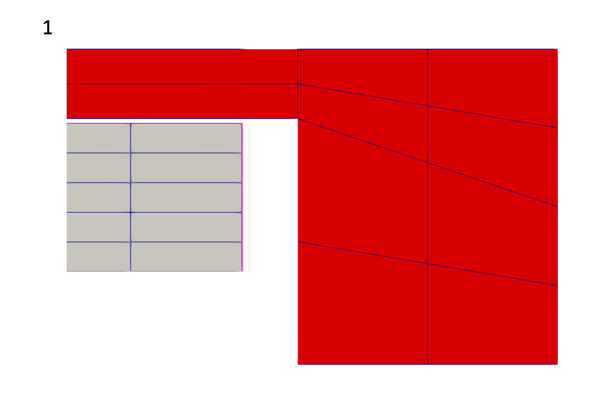
Figure 4: A close up of the fuel pin mesh, Area 1, showing the gap between the 'Sleeve_top' (the section of the graphite sleeve to the right, in red) and the 'Fuel_top' (the section of the fuel pin to the left, in grey), where heat transfer takes place; the boundaries are shown as faint pink lines.
[ThermalContact]
  [gap_side]
    type = GapHeatTransfer
    gap_geometry_type = 'CYLINDER'
    emissivity_primary = 0.8 # MHTGR: 0.85, Shi PhD: 0.8
    emissivity_secondary = 0.8 # MHTGR: 0.85, Shi PhD: 0.8
    primary = Sleeve_side
    secondary = Fuel_side
    gap_conductivity = 0.2735 # He at 668K, 2.8 MPa - Original: 1e-5 W/m/K, Shi PhD: 0.35 (but no gap on the inside)
    variable = temp
    quadrature = true
  []
[]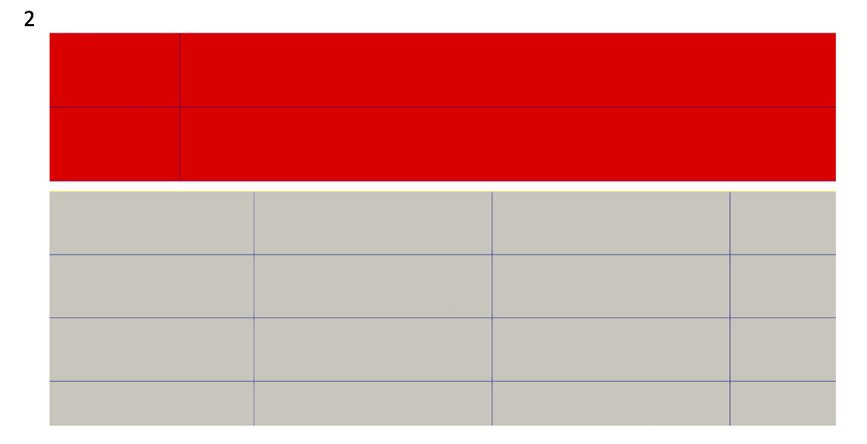
Figure 5: A close up of the fuel pin mesh, Area 2, showing the 'Sleeve_side' (the section of the graphite sleeve at the top, in red) and the 'Fuel_side' (the section of the fuel pin at the bottom, in grey), which contains a very slight gap in which heat transfer takes place. The boundaries are shown as faint blue and yellow lines.
[ThermalContact]
  [cooling_channel]
    type = GapHeatTransfer
    gap_geometry_type = 'CYLINDER'
    emissivity_primary = 0.8 # MHTGR: 0.85, Shi PhD: 0.8
    emissivity_secondary = 0.8 # MHTGR: 0.85, Shi PhD: 0.8
    primary = Inner_outer_ring
    secondary = Relap7_Tw
    gap_conductivity = 0.2309 # He at 523K, 2.8MPa
    variable = temp
    quadrature = true
  []
[]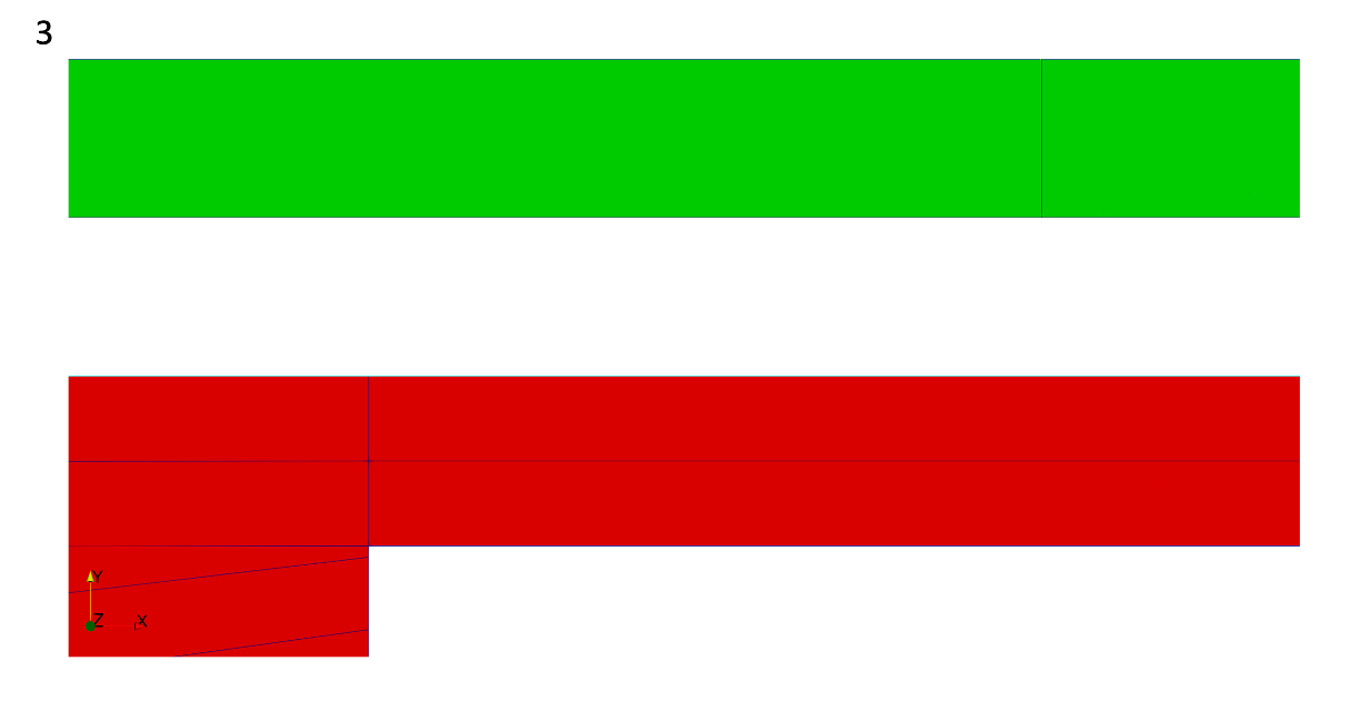
Figure 6: A close up of the fuel pin mesh, Area 3, showing the gap between the 'Inner_outer_ring' (the outer wall of the graphite sleeve, in red) and the 'Relap7_Tw' (the inner wall of the graphite block, in green) where heat transfer takes place. The boundaries are shown as faint teal and black lines.
Boundary Conditions (BCs)
We impose a zero heat flux using a Neumann boundary condition on the bottom of the graphite sleeve.
[BCs]
  [Neumann]
    type = NeumannBC
    variable = temp
    value = 0.0
    boundary = 'Neumann Sleeve_bot'
  []
[]A pseudo-Dirichlet boundary is also defined; it weakly imposes 'T = Tmod' on the outer most radial wall of the graphite block.
[BCs]
  [outside_bc]
    type = CoupledConvectiveHeatFluxBC
    variable = temp
    boundary = 'Outer_outer_ring'
    T_infinity = Tmod
    htc = 1e5
  []
[]The convective heat transfer with the helium channel is modeled using 'CoupledConvectiveHeatFluxBC'.
The 'convective_inner' block specifies a heat transfer coefficient for the inner radius of the cooling channel in W/K/.
[BCs]
  [convective_inner]
    type = CoupledConvectiveHeatFluxBC
    boundary = 'Relap7_Tw'
    variable = temp
    T_infinity = Tfluid
    htc = Hw_inner
  []
[]The 'convective_outer' block specifies a heat transfer coefficient for the outer radius of the cooling channel in W/K/.
[BCs]
  [convective_outer]
    type = CoupledConvectiveHeatFluxBC
    boundary = 'Inner_outer_ring'
    variable = temp
    T_infinity = Tfluid
    htc = Hw_outer
  []
[]Kernels
The 'Kernels' block defines a steady-state heat conduction equation. A source term is defined using the 'CoupledForce' kernel to model how much power is deposited in the fuel compact.
[Kernels]
  [heat]
    type = HeatConduction
    variable = temp
  []
  # [heat_ie] # omit to speed up steady state convergence
  #   type = HeatConductionTimeDerivative
  #   variable = temp
  # []
  [heat_source]
    type = CoupledForce
    variable = temp
    block = '${fuel_blocks}'
    v = scaled_power_density
  []
[]Thermal-Hydraulics
The thermal-hydraulics calculations in the coolant channels use the NEAMS code RELAP-7, Berry et al. (2014).
One cooling flow channel is simulated for each of the 30 fuel columns. Another flow channel simulation is performed for each of the 16 control rod channels. The cooling flow simulation is represented below in Figure 1, Labouré et al. (2022); the cold helium flows downwards from the top of the reactor core through the control rod channels and the fuel rod channels to cool the fuel pins.
Fuel cooling channels have a specified mass flow rate applied that is different from the mass flow rate applied to the CR cooling channels. To simplify the coolant flow path of the HTTR, the flow in inter-column gaps is neglected and the bypass flow is set to a fixed value.
.](../../media/htgr/httr/ThermalHydraulics.png)
Figure 1: Left: Radial cross-section of the Serpent model. Right: description of the RELAP-7 models for fuel and CR channels, at the example locations shown in the core view, from Labouré et al. (2022).
Thermal-Hydraulics - Control Rods
Components
The 'CR_cooling_channel' block describes the flow channels' position, orientation, and length to create 300 elements of equal length while providing the area of the pipe, hydraulic diameter, and wall friction.
[Components]
  [CR_cooling_channel]
    type = FlowChannel1Phase
    fp = helium
    # Geometry
    position = '5.22 0 0'
    orientation = '-1.0 0 0'
    A = '${fparse 0.25 * pi * D_ext * D_ext}' # Area of the pipe m^2
    D_h = ${D_ext} # Hydraulic diameter A = Dout
    f = 0 # Wall friction

    length = 5.22 # m
    n_elems = 300
  []
[]The 'inlet' block defines the cooling channel inlet and imposes the temperature of the fluid and the mass flow rate, which are both constants.
[Components]
  [inlet]
    type = InletMassFlowRateTemperature1Phase
    input = 'CR_cooling_channel:in'
    m_dot = ${mdot}
    T = ${Tinlet} # K
  []
[]The 'outlet' block defines the cooling channel outlet and imposes the value of the pressure as a constant, as an outlet boundary condition.
[Components]
  [outlet]
    type = Outlet1Phase
    input = 'CR_cooling_channel:out'
    p = ${pressure}
  []
[]The 'ht_ext' block defines a convective boundary condition using the 'HeatTransferFromExternalAppTemperature1Phase'. This heat structure is attached to the flow channel by specifying the 'flow_channel' parameter.
[Components]
  [ht_ext]
    type = HeatTransferFromExternalAppTemperature1Phase
    flow_channel = CR_cooling_channel
    P_hf = '${fparse pi * D_ext}' # Heat flux perimeter m
    initial_T_wall = 500
  []
[]Fluid Properties
In the 'FluidProperties' block, we use the Spline Based Table Lookup fluid properties for Helium.
Helium SBTL properties are available as a submodule of RELAP-7. If your access level does not provide them, please contact the MOOSE team for access. They should be open-sourced shortly.
[FluidProperties]
  [helium]
    type = HeliumSBTLFluidProperties
  []
[]Thermal-Hydraulics - Fuel Pins
Components
The Components block sets up the geometry for the cooling channels, heat transfers for the flow channels, and boundary conditions to couple to the graphite moderator blocks and fuel pins. The pipe is broken up into three sections to account for the upper and lower reflectors (which contain no fuel). The interior and exterior wall temperatures and heated perimeter are specified to model the heat transfer throughout the cooling channel.
The 'pipe_top', 'pipe1', and 'pipe_bottom' blocks define a 'FlowChannel1Phase' type as well as the position, orientation, and length of this section of the pipe. It specifies the area and hydraulic diameter as constants; 'pipe1' uses a different hydraulic diameter than 'pipe_top' and 'pipe_bottom' to account for the fuel pin inside the cooling channel. 60 'pipe_top' elements, 180 'pipe1' elements, and 60 'pipe_bottom' elements are requested.
[Components]
  [pipe_top]
    type = FlowChannel1Phase
    fp = helium
    # Geometry
    position = '5.22 0 0'
    orientation = '-1.0 0 0'
    A = '${fparse 0.25 * pi * D_ext * D_ext}' # Area of the pipe m^2
    D_h = ${D_ext} # Hydraulic diameter A = Dout
    f = 0 # Wall friction

    length = 1.16 # m
    n_elems = 60
  []
[][Components]
[pipe1]
type = FlowChannel1Phase
fp = helium
# Geometry
position = '4.06 0 0'
orientation = '-1.0 0 0'
A = '${fparse 0.25 * pi * (D_ext * D_ext - D_int * D_int)}' # Area of the pipe m^2
D_h = '${fparse D_ext - D_int}' # Hydraulic diameter A = Dout-Din
f = 0 # Wall friction
length = 2.9 # m
n_elems = 180
[]
[][Components]
[pipe_bottom]
type = FlowChannel1Phase
fp = helium
# Geometry
position = '1.16 0 0'
orientation = '-1.0 0 0'
A = '${fparse 0.25 * pi * D_ext * D_ext}' # Area of the pipe m^2
D_h = ${D_ext} # Hydraulic diameter A = Dout
f = 0 # Wall friction
length = 1.16
n_elems = 60
[]
[]The 'inlet' block defines the cooling channel inlet as an 'InletMassFlowRateTemperature1Phase' type. It imposes the temperature of the inlet and the mass flow rate, which are both constants.
[Components]
  [inlet]
    type = InletMassFlowRateTemperature1Phase
    input = 'pipe_top:in'
    m_dot = ${mdot}
    T = ${Tinlet} # K
  []
[]The 'junction1' block defines the junction connecting 'pipe_top' to 'pipe1'.
[Components]
  [junction1]
    type = JunctionOneToOne1Phase
    connections = 'pipe_top:out pipe1:in'
  []
[]The 'junction2' block defines the junction connecting 'pipe1' to 'pipe_bottom'.
[Components]
  [junction2]
    type = JunctionOneToOne1Phase
    connections = 'pipe1:out pipe_bottom:in'
  []
[]The 'outlet' block imposes the pressure of helium as it exits the cooling channel as a constant.
[Components]
  [outlet]
    type = Outlet1Phase
    input = 'pipe_bottom:out'
    p = ${pressure}
  []
[]The 'ht_int' block defines the BC on the interior radius of the cooling channel. It specifies a heat flux perimeter as a constant and has an initial wall temperature of 600K.
The 'ht_ext_top' block defines the BC on the exterior radius, the 'ht_ext' block defines the BC on the interior radius, and the 'ht_ext_bottom' block defines the BC on the exterior radius of the cooling channel. Each block specifies in a heat flux perimeter as a constant and has an initial wall temperature of 500K.
[Components]
  [ht_int]
    type = HeatTransferFromExternalAppTemperature1Phase
    flow_channel = pipe1
    P_hf = '${fparse pi * D_int}' # Heat flux perimeter m
    initial_T_wall = 600
  []
[][Components]
[ht_ext_top]
type = HeatTransferFromExternalAppTemperature1Phase
flow_channel = pipe_top
P_hf = '${fparse pi * D_ext}' # Heat flux perimeter m
initial_T_wall = 500
[]
[][Components]
[ht_ext]
type = HeatTransferFromExternalAppTemperature1Phase
flow_channel = pipe1
P_hf = '${fparse pi * D_ext}' # Heat flux perimeter m
initial_T_wall = 500
[]
[][Components]
[ht_ext_bottom]
type = HeatTransferFromExternalAppTemperature1Phase
flow_channel = pipe_bottom
P_hf = '${fparse pi * D_ext}' # Heat flux perimeter m
initial_T_wall = 500
[]
[]Coupled Multiphysics Model
The HTTR model released is a multiphysics model that combines 3-D full core super homogenization-corrected neutronics, macroscale 3-D full core homogenized heat transfer, 2-D axisymmetric pin-scale fuel rod heat transfer, and distributed 1-D thermal-hydraulics channels Laboure et al. (2019), shown below in Figure 2. The HTTR model released utilizes the MOOSE framework's MultiApps and Transfers systems to couple the individual physics models.
.](../../media/htgr/httr/Coupling.png)
Figure 2: Workflow of the steady-state coupling, from Labouré et al. (2022).
Coupling Neutronics and Heat Conduction
The homogeneous full core heat conduction solve is a child application of the neutronics application. This is selected because the neutronics solve is solved for steady state directly as an eigenvalue problem, while some of the downstream simulations are relaxation to steady-state transients.
[MultiApps]
  [moose_modules]
    type = FullSolveMultiApp
    positions = '0 0 0'
    input_files = full_core_ht_steady.i
    execute_on = 'timestep_end'
    keep_solution_during_restore = true # to restart from the latest solve of the multiapp (for pseudo-transient)
  []
[]The neutronics data (local power) is sent to the homogenized heat conduction model, which then sends fuel temperature data back to the neutronics model.
[Transfers]
  [pdens_to_modules]
    type = MultiAppProjectionTransfer
    to_multi_app = moose_modules
    source_variable = power_density
    variable = power_density
    execute_on = 'timestep_end'
  []
  [tmod_from_modules]
    type = MultiAppProjectionTransfer
    from_multi_app = moose_modules
    source_variable = Tmod
    variable = Tmod
    execute_on = 'timestep_end'
  []
  [tfuel_from_modules]
    type = MultiAppProjectionTransfer
    from_multi_app = moose_modules
    source_variable = Tfuel
    variable = Tfuel
    execute_on = 'timestep_end'
  []
[]Coupling Homogenized Heat Conduction and Heterogenous Heat Conduction
.](../../media/htgr/httr/MultiphysicsCoupling.png)
Figure 4: Relationship between various sub-models, from Laboure et al. (2019).
Distributed heterogeneous single pin heat transfer simulations and distributed thermal-hydraulics cooling channel calculations are created using MultiApps.
[MultiApps]
  [bison]
    type = TransientMultiApp
    positions_file = '../mesh/centers_relap_33pins.txt
                      ../mesh/centers_relap_31pins.txt'
    input_files = 'fuel_elem_steady.i'
    cli_args = 'npins=33 npins=33 npins=33 npins=33 npins=33 npins=33 npins=33 npins=33 npins=33 npins=33 npins=33 npins=33
                npins=31 npins=31 npins=31 npins=31 npins=31 npins=31 npins=31 npins=31 npins=31 npins=31 npins=31 npins=31 npins=31 npins=31 npins=31 npins=31 npins=31 npins=31'
    execute_on = 'timestep_begin'
    output_in_position = true
  []
  [relap]
    type = TransientMultiApp
    positions_file = '../mesh/centers_relap_33pins.txt
                      ../mesh/centers_relap_31pins.txt
                      ../mesh/centers_relap_CR.txt'
    # the first 12 positions are fuel with 33 pins, the next 18 are fuel with 31 pins, the last 16 are CR
    input_files = 'thermal_hydraulics_fuel_pins_steady.i
                   thermal_hydraulics_fuel_pins_steady.i
                   thermal_hydraulics_CR_steady.i'
    cli_args = 'npins=33 npins=33 npins=33 npins=33 npins=33 npins=33 npins=33 npins=33 npins=33 npins=33 npins=33 npins=33
                npins=31 npins=31 npins=31 npins=31 npins=31 npins=31 npins=31 npins=31 npins=31 npins=31 npins=31 npins=31 npins=31 npins=31 npins=31 npins=31 npins=31 npins=31
                npins=2  npins=2  npins=2  npins=2  npins=2  npins=2  npins=2  npins=2  npins=2  npins=2  npins=2  npins=2  npins=2  npins=2  npins=2  npins=2'
    execute_on = 'timestep_end'
    max_procs_per_app = 1
    sub_cycling = true
  []
[]The homogenized heat transfer model sends gap conductance information to the single pin heterogeneous heat transfer model and sleeve temperature data to both thermal-hydraulics models.
Power density, moderator temperature, fluid temperature, and temperatures of the inner and outer radius of fuel and cooling rod channel walls are all sent to the Bison Heat Transfer application.
[Transfers]
  [pdens_to_bison]
    type = MultiAppUserObjectTransfer
    to_multi_app = bison
    user_object = average_power_UO
    variable = power_density
  []
[][Transfers]
[tmod_to_bison]
type = MultiAppUserObjectTransfer
to_multi_app = bison
user_object = average_Tsolid_UO
variable = Tmod
[]
[][Transfers]
[tfluid_to_bison]
type = MultiAppInterpolationTransfer
to_multi_app = bison
source_variable = Tfluid
variable = Tfluid
[]
[][Transfers]
[htc_inner_to_bison]
type = MultiAppInterpolationTransfer
to_multi_app = bison
source_variable = Hw_inner
variable = Hw_inner
[]
[][Transfers]
[htc_outer_to_bison]
type = MultiAppInterpolationTransfer
to_multi_app = bison
source_variable = Hw_outer
variable = Hw_outer
[]
[]Average fuel temperature, graphite sleeve temperature, inner radius temperature of the fuel and cooling rod channel walls, gap conductance heat source, total heat flux, and total power are then sent back from the Bison Heat Transfer application after further calculations have been made.
[Transfers]
  [tfuel_from_bison]
    type = MultiAppUserObjectTransfer
    from_multi_app = bison
    user_object = average_Tfuel_UO
    variable = Tfuel
    nearest_sub_app = true
  []
[][Transfers]
[tsleeve_from_bison]
type = MultiAppUserObjectTransfer
from_multi_app = bison
user_object = average_Tsleeve_UO
variable = Tsleeve
nearest_sub_app = true
[]
[][Transfers]
[twall_from_bison]
type = MultiAppUserObjectTransfer
from_multi_app = bison
user_object = inner_wall_temp_UO
variable = inner_Twall
nearest_sub_app = true
[]
[][Transfers]
[heat_source_from_bison]
type = MultiAppUserObjectTransfer
from_multi_app = bison
user_object = gap_conductance_UO
variable = gap_conductance
nearest_sub_app = true
[]
[][Transfers]
[total_power_from_bison]
type = MultiAppPostprocessorTransfer
from_multi_app = bison
from_postprocessor = 'fuel_block_total_power'
to_postprocessor = 'bison_total_power'
reduction_type = sum
[]
[][Transfers]
[bison_heat_flux]
type = MultiAppPostprocessorTransfer
from_multi_app = bison
from_postprocessor = 'bdy_heat_flux_tot'
to_postprocessor = 'bison_total_bdy_heat_flux'
reduction_type = sum
[]
[]Inner wall temperatures and outer wall temperatures of the fuel cooling channels are sent to the RELAP7 Thermal-Hydraulics application.
[Transfers]
  [inner_twall_to_relap]
    type = MultiAppInterpolationTransfer
    to_multi_app = relap
    source_variable = inner_Twall
    variable = T_wall:1
  []
[][Transfers]
[tmod_to_relap]
type = MultiAppUserObjectTransfer
to_multi_app = relap
user_object = average_Tsolid_UO
variable = T_wall:2
[]
[][Transfers]
[tmod_to_relap_topbottom]
type = MultiAppUserObjectTransfer
to_multi_app = relap
user_object = average_Tsolid_UO
variable = T_wall
[]
[]Fluid temperature, homogenized outer wall heat transfer coefficient, outlet temperature, and enthalpy difference are then sent back from the RELAP7 Thermal-Hydraulics application. The heat transfer coefficients and fluid temperatures can be used to compute the heat flux to verify conservation. The temperatures fields are also gathered to the parent application for output of the fluid temperature on the core scale.
[Transfers]
  [tfluid_from_relap]
    type = MultiAppUserObjectTransfer
    from_multi_app = relap
    variable = Tfluid
    user_object = avg_Tfluid_UO
    nearest_sub_app = true
  []
[][Transfers]
[hw_inner_from_relap]
type = MultiAppUserObjectTransfer
from_multi_app = relap
variable = Hw_inner
user_object = avg_Hw_inner_UO
nearest_sub_app = true
[]
[][Transfers]
[hw_outer_from_relap]
type = MultiAppUserObjectTransfer
from_multi_app = relap
variable = Hw_outer
user_object = avg_Hw_outer_UO
nearest_sub_app = true
[]
[][Transfers]
[hw_outer_homo_from_relap]
type = MultiAppUserObjectTransfer
from_multi_app = relap
variable = Hw_outer_homo
user_object = avg_Hw_outer_homo_UO
nearest_sub_app = true
[]
[][Transfers]
[tout_from_relap]
type = MultiAppPostprocessorTransfer
from_multi_app = relap
from_postprocessor = Tout_weighted
to_postprocessor = Tfluid_out
reduction_type = sum
[]
[][Transfers]
[deltaH_from_relap]
type = MultiAppPostprocessorTransfer
from_multi_app = relap
from_postprocessor = delta_H
to_postprocessor = delta_H
reduction_type = sum
[]
[]Files
Cross section Files:
The cross sections are located in httr/cross_sections.
Multigroup cross-section library with Xe-135 contribution removed - HTTR_5x5_9MW_profiled_VR_kappa_adjusted.xml
SPH factor library - HTTR_5x5_9MW_equiv_corrected.xml
Mesh Files:
Mesh files are located under httr/mesh.
Griffin full-core mesh - full_core_HTTR.e
Full-core heat transfer mesh - thermal_mesh_in.e
BISON 5-pin mesh - HTTR_fuel_pin_2D_refined_m_5pins_axialref.e
Input Files:
Input files are located in httr/steady_state_and_null_transient.
Steady-State Model
Griffin model - neutronics_eigenvalue.i
Full-core heat transfer model - full_core_ht_steady.i
BISON 5-pin model - fuel_elem_steady.i
RELAP-7 Control Rod Assembly thermal-hydraulics model - thermal_hydraulics_CR_steady.i
RELAP-7 Fuel Assembly thermal-hydraulics model - thermal_hydraulics_fuel_pins_steady.i
Running the simulation
To apply for access to Sabertooth and access to INL High Performance Computing, please visit NCRC. These inputs can be run on your local machine or on a computing cluster, depending on your level of access to the simulation software and the computing power available to you.
Idaho National Laboratory HPC
Run the Griffin parent application input with Sabertooth. With at least level 1 access to Sabertooth, the sabertooth module can be loaded and from the sabertooth-opt executable can be used. The neutronics_eigenvalue.i input is the input for the steady state calculation. The null transient is considered on this page.
module load use.moose moose-apps sabertooth

mpirun -n 6 sabertooth-opt -i neutronics_eigenvalue.i
Local Device
In all cases (steady-state and null-transient - which should be executed in this order), run the Griffin input with Sabertooth.
For instance, if you have level 2 access to the binaries, you can download sabertooth through miniconda and use them (once downloaded) as follows:
conda activate sabertooth

mpirun -n 6 sabertooth-opt -i neutronics_eigenvalue.i
If using or modifying this model, please cite:
1. Vincent Labouré, Javier Ortensi, Nicolas Martin, Paolo Balestra, Derek Gaston, Yinbin Miao, Gerhard Strydom, "Improved multiphysics model of the High Temperature Engineering Test Reactor for the simulation of loss-of-forced-cooling experiments", Annals of Nuclear Energy, Volume 189, 2023, 109838, ISSN 0306-4549, https://doi.org/10.1016/j.anucene.2023.109838. (https://www.sciencedirect.com/science/article/pii/S0306454923001573)
2. Vincent M Laboure, Matilda A Lindell, Javier Ortensi, Gerhard Strydom and Paolo Balestra, "FY22 Status Report on the ART-GCR CMVB and CNWG International Collaborations." INL/RPT-22-68891-Rev000 Web. doi:10.2172/1893099.
Documentation written by Kylee Swanson.
References
- R. A. Berry, J. W. Peterson, H. Zhang, R. C. Martineau, H. Zhao, L. Zou, and D. Andrš.
RELAP-7 Theory Manual.
Technical Report INL/EXT-14-31366, Idaho National Laboratory, 2014.[BibTeX]
@TechReport{relap7, author = "Berry, R. A. and Peterson, J. W. and Zhang, H. and Martineau, R. C. and Zhao, H. and Zou, L. and Andr\v{s}, D.", title = "{{RELAP-7} Theory Manual}", institution = "Idaho National Laboratory", year = "2014", number = "INL/EXT-14-31366" } - Mark DeHart, Fredrick N. Gleicher, Vincent Laboure, Javier Ortensi, Zachary Prince, Sebastian Schunert, and Yaqi Wang.
Griffin user manual.
Technical Report INL/EXT-19-54247, Idaho National Laboratory, 2020.[BibTeX]
@techreport{Griffin2020, author = "DeHart, Mark and Gleicher, Fredrick N. and Laboure, Vincent and Ortensi, Javier and Prince, Zachary and Schunert, Sebastian and Wang, Yaqi", title = "Griffin User Manual", institution = "Idaho National Laboratory", number = "INL/EXT-19-54247", year = "2020" } - Vincent Laboure, Javier Ortensi, Yaqi Wang, Sebastian Schunert, Frederick Gleicher, Mark Dehart, and R. Martineau.
Multiphysics Steady-State Simulation of the High Temperature Test Reactor with MAMMOTH, BISON and RELAP-7.
Technical Report, Idaho National Laboratory, 2019.[BibTeX]
@techreport{INL/CON-18-52202-Revision-0, author = "Laboure, Vincent and Ortensi, Javier and Wang, Yaqi and Schunert, Sebastian and Gleicher, Frederick and Dehart, Mark and Martineau, R.", year = "2019", title = "{Multiphysics Steady-State Simulation of the High Temperature Test Reactor with MAMMOTH, BISON and RELAP-7}", institution = "Idaho National Laboratory" } - Vincent M. Labouré, Matilda Anna Elisabeth Åberg Lindell, Javier Ortensi, Gerhard Strydom, and Paolo Balestra.
FY22 Status Report on the ART-GCR CMVB and CNWG International Collaborations.
Technical Report, Idaho National Laboratory, 2022.
doi:10.2172/1893099.[BibTeX]
@techreport{osti_1893099, author = "Labouré, Vincent M. and Åberg Lindell, Matilda Anna Elisabeth and Ortensi, Javier and Strydom, Gerhard and Balestra, Paolo", title = "{FY22 Status Report on the ART-GCR CMVB and CNWG International Collaborations}", doi = "10.2172/1893099", year = "2022", institution = "Idaho National Laboratory" } - Richard L. Williamson, Jason D. Hales, Stephen R. Novascone, Giovanni Pastore, Kyle A. Gamble, Benjamin W. Spencer, Wen Jiang, Stephanie A. Pitts, Albert Casagranda, Daniel Schwen, Adam X. Zabriskie, Aysenur Toptan, Russell Gardner, Christoper Matthews, Wenfeng Liu, and Hailong Chen.
Bison: a flexible code for advanced simulation of the performance of multiple nuclear fuel forms.
Nuclear Technology, 207(7):1–27, 2021.
URL: https://doi.org/10.1080/00295450.2020.1836940, doi:10.1080/00295450.2020.1836940.[BibTeX]
@article{BISON,
    author = "Williamson, Richard L. and Hales, Jason D. and Novascone, Stephen R. and Pastore, Giovanni and Gamble, Kyle A. and Spencer, Benjamin W. and Jiang, Wen and Pitts, Stephanie A. and Casagranda, Albert and Schwen, Daniel and Zabriskie, Adam X. and Toptan, Aysenur and Gardner, Russell and Matthews, Christoper and Liu, Wenfeng and Chen, Hailong",
    title = "BISON: A Flexible Code for Advanced Simulation of the Performance of Multiple Nuclear Fuel Forms",
    journal = "Nuclear Technology",
    volume = "207",
    number = "7",
    pages = "1-27",
    year = "2021",
    publisher = "Taylor \& Francis",
    doi = "10.1080/00295450.2020.1836940",
    URL = "https://doi.org/10.1080/00295450.2020.1836940"
}
(htgr/httr/steady_state_and_null_transient/neutronics_eigenvalue.i)
# ==============================================================================
# Full-core homogenized neutronics model (steady-state)
# Application: Griffin (Sabertooth with child applications)
# ------------------------------------------------------------------------------
# Idaho Falls, INL, April 2023
# Author(s): Vincent Laboure
# If using or referring to this model, please cite as explained in
# https://mooseframework.inl.gov/virtual_test_bed/citing.html
# ==============================================================================

# Defining i as the axial layer index (1 being the top and 18 the bottom), we have the following block IDs:
# 1050 + i: fuel columns of type 1
# 1150 + i: fuel columns of type 2
# 1250 + i: fuel columns of type 3
# 1350 + i: fuel columns of type 4
# 1450 + i: RR columns
# 1550 + i: PR columns
# 2050 + i: CR column, type C
# 2150 + i: CR columns, type R1 without neutron sources for i = 5-6
# 2170 + i: CR columns, type R1 with neutron sources for i = 5-6 (only modeled during transient)
# 2250 + i: CR columns, type R2
# 2350 + i: I columns,
# 2450 + i: CR columns, type R3

# Block IDs of fuel regions (to be SPH corrected)
fuel_blocks = '
1055 1056 1057 1058 1059 1060 1061 1062 1063 1064
1155 1156 1157 1158 1159 1160 1161 1162 1163 1164
1255 1256 1257 1258 1259 1260 1261 1262 1263 1264
1355 1356 1357 1358 1359 1360 1361 1362 1363 1364
'

# Block IDs of non-fuel (CR, RR, I) stack regions to be SPH corrected (active core + one layer of axial reflector on top and bottom)
sph_nonfuel_blocks = '
1054                                                   1065
1154                                                   1165
1254                                                   1265
1354                                                   1365
1454 1455 1456 1457 1458 1459 1460 1461 1462 1463 1464 1465
2054 2055 2056 2057 2058 2059 2060 2061 2062 2063 2064 2065
2154 2155 2156 2157 2158 2159 2160 2161 2162 2163 2164 2165
2174 2175 2176 2177 2178 2179 2180 2181 2182 2183 2184 2185
2254 2255 2256 2257 2258 2259 2260 2261 2262 2263 2264 2265
2354 2355 2356 2357 2358 2359 2360 2361 2362 2363 2364 2365
2454 2455 2456 2457 2458 2459 2460 2461 2462 2463 2464 2465
'

# Block IDs of the part of the axial reflector to not be SPH corrected (3 layers on top and bottom)
axial_reflector_blocks = '
1051 1052 1053 1066 1067 1068 2051 2052 2053 2066 2067 2068
1151 1152 1153 1166 1167 1168 2151 2152 2153 2166 2167 2168 2171 2172 2173 2186 2187 2188
1251 1252 1253 1266 1267 1268 2251 2252 2253 2266 2267 2268
1351 1352 1353 1366 1367 1368 2351 2352 2353 2366 2367 2368
1451 1452 1453 1466 1467 1468 2451 2452 2453 2466 2467 2468
'

# Block IDs of the permanent reflector (PR)
radial_reflector_blocks = '
1551 1552 1553 1554 1555 1556 1557 1558 1559 1560 1561 1562 1563 1564 1565 1566 1567 1568
'

x1 = 4.06 # m - bottom of active fuel region
x2 = 1.16 # m - top of active fuel region
Tinlet = 453.15 # fluid inlet temperature
Toutlet = 593.15 # (expected) fluid outlet temperature

initial_decay_heat = 5.7472e5 # decay heat for 9MW steady-state, in W
total_power = 9e6 # total power (including decay heat), in W
fission_power = '${fparse total_power - initial_decay_heat}'

extension = '_9MW'

[Mesh]
  [fmg]
    type = FileMeshGenerator
    file = '../mesh/full_core/full_core_HTTR.e'
    exodus_extra_element_integers = 'material_id equivalence_id'
  []
  # Restart relies on the ExodusII_IO functionality, which only works with ReplicatedMesh.
  parallel_type = replicated
[]

[TransportSystems]
  particle = neutron
  equation_type = eigenvalue
  G = 10
  VacuumBoundary = '1 2 3'
  use_custom_bxnorm_for_eigenvalue = true

  [diff]
    scheme = CFEM-Diffusion
    n_delay_groups = 6
    assemble_scattering_jacobian = true
    assemble_fission_jacobian = true
    assemble_delay_jacobian = true
  []
[]

[Equivalence]
  type = SPH
  transport_system = diff
  compute_factors = false
  equivalence_library = '../cross_sections/HTTR_5x5${extension}_equiv_corrected.xml'
  library_name = 'HTTR_5x5_equiv${extension}'

  equivalence_grid_names = 'Tfuel Tmod'
  equivalence_grid_variables = 'Tfuel Tmod'
  sph_block = '${fuel_blocks} ${sph_nonfuel_blocks}'
[]

[PowerDensity]
  power = ${fission_power}
  power_density_variable = power_density
  integrated_power_postprocessor = integrated_power
  # activates poison tracking
  poison_tracking_chains = 'XE135'
[]

[GlobalParams]
  # for materials
  library_file = '../cross_sections/HTTR_5x5${extension}_profiled_VR_kappa_adjusted.xml'
  library_name = 'HTTR_5x5${extension}'
  isotopes = 'pseudo'
  densities = '1.0'
  is_meter = true
  grid_names = 'Tfuel Tmod'
  grid_variables = 'Tfuel Tmod'
  constant_on = ELEMENT
[]

[Materials]
  [fuel_sph]
    type = CoupledFeedbackMatIDNeutronicsMaterial
    block = '${fuel_blocks}'
    plus = true
  []
  [nonfuel_sph]
    type = CoupledFeedbackMatIDNeutronicsMaterial
    block = '${sph_nonfuel_blocks}'
  []
  [nonsph]
    type = CoupledFeedbackMatIDNeutronicsMaterial
    block = '${axial_reflector_blocks} ${radial_reflector_blocks}'
  []
[]

[AuxVariables]
  [Tfuel]
    initial_condition = 620
    order = CONSTANT
    family = MONOMIAL
  []
  [Tmod]
    # initial_condition = 700
    order = FIRST
    family = L2_LAGRANGE
  []
[]

[ICs]
  [Tmod_ic]
    type = FunctionIC
    variable = Tmod
    function = Tsolid_init_func
  []
[]

[Functions]
  [Tsolid_init_func] # initial guess for moderator temperature
    type = ParsedFunction
    # value = '${Tinlet} + (5.22 - x) * (${Toutlet} - ${Tinlet}) / 5.22'
    expression = 'if(x < ${x2}, ${Toutlet},
             if(x > ${x1}, ${Tinlet},
                          (${Tinlet} - ${Toutlet}) * (x - ${x2}) / (${x1} - ${x2}) + ${Toutlet}))'
  []
[]

[Postprocessors]
  [Tm_avg]
    type = ElementAverageValue
    variable = Tmod
    execute_on = 'initial timestep_end'
  []
  [Tf_avg]
    type = ElementAverageValue
    variable = Tfuel
    execute_on = 'initial timestep_end'
  []
  [Tm_max]
    type = ElementExtremeValue
    value_type = max
    variable = Tmod
    execute_on = 'initial timestep_end'
  []
  [Tf_max]
    type = ElementExtremeValue
    value_type = max
    variable = Tfuel
    execute_on = 'initial timestep_end'
  []
  [NI_avg]
    type = ElementIntegralArrayVariablePostprocessor
    variable = poison_tracking
    component = 0
    block = '${fuel_blocks}'
  []
  [NXe_avg]
    type = ElementIntegralArrayVariablePostprocessor
    variable = poison_tracking
    component = 1
    block = '${fuel_blocks}'
  []
[]

[UserObjects]
  [ss_temperatures]
    type = SolutionVectorFile
    var = 'Tfuel Tmod'
    writing = true
    execute_on = 'final'
  []
  [restart_poison_densities]
    type = SolutionVectorFile
    var = 'poison_tracking'
    writing = true
    execute_on = 'final'
  []
[]

[Preconditioning]
  [SMP]
    type = SMP
    off_diag_row = '
                       sflux_g1
                       sflux_g2
                       sflux_g3
                       sflux_g4
                       sflux_g5 sflux_g5
                       sflux_g6 sflux_g6 sflux_g6 sflux_g6
                       sflux_g7 sflux_g7 sflux_g7
                       sflux_g8 sflux_g8 sflux_g8
                       sflux_g9
                      '
    off_diag_column = '
                       sflux_g0
                       sflux_g1
                       sflux_g2
                       sflux_g3
                       sflux_g4 sflux_g6
                       sflux_g5 sflux_g7 sflux_g8 sflux_g9
                       sflux_g6 sflux_g8 sflux_g9
                       sflux_g6 sflux_g7 sflux_g9
                       sflux_g8
                      '
  []
[]

[Executioner]
  type = Eigenvalue

  petsc_options_iname = '-pc_type -pc_hypre_type -ksp_gmres_restart '
  petsc_options_value = 'hypre boomeramg 100'
  line_search = none # default seems bad for convergence

  free_power_iterations = 2

  automatic_scaling = true
  nl_abs_tol = 1e-11
  nl_rel_tol = 1e-11
  l_tol = 1e-2

  fixed_point_rel_tol = 1e-7
  fixed_point_abs_tol = 5e-6 # may start stagnating below that tolerance (double check)
  fixed_point_max_its = 5 #10
  accept_on_max_fixed_point_iteration = true
  disable_fixed_point_residual_norm_check = false
[]

[MultiApps]
  [moose_modules]
    type = FullSolveMultiApp
    positions = '0 0 0'
    input_files = full_core_ht_steady.i
    execute_on = 'timestep_end'
    keep_solution_during_restore = true # to restart from the latest solve of the multiapp (for pseudo-transient)
  []
[]

[Transfers]
  [pdens_to_modules]
    type = MultiAppProjectionTransfer
    to_multi_app = moose_modules
    source_variable = power_density
    variable = power_density
    execute_on = 'timestep_end'
  []
  [tmod_from_modules]
    type = MultiAppProjectionTransfer
    from_multi_app = moose_modules
    source_variable = Tmod
    variable = Tmod
    execute_on = 'timestep_end'
  []
  [tfuel_from_modules]
    type = MultiAppProjectionTransfer
    from_multi_app = moose_modules
    source_variable = Tfuel
    variable = Tfuel
    execute_on = 'timestep_end'
  []
[]

[Outputs]
  file_base = neutronics_eigenvalue${extension}

  [exodus]
    type = Exodus
    overwrite = true
  []

  csv = true
  perf_graph = true
[]
(htgr/httr/steady_state_and_null_transient/full_core_ht_steady.i)
# ==============================================================================
# Full-core homogenized heat transfer model (steady-state)
# Application: BISON (Sabertooth with child applications)
# ------------------------------------------------------------------------------
# Idaho Falls, INL, April 2023
# Author(s): Vincent Laboure
# If using or referring to this model, please cite as explained in
# https://mooseframework.inl.gov/virtual_test_bed/citing.html
# ==============================================================================
# Defining i as the axial layer index (1 being the top and 18 the bottom), we have the following block IDs:
# 1050 + i: fuel columns of type 1
# 1150 + i: fuel columns of type 2
# 1250 + i: fuel columns of type 3
# 1350 + i: fuel columns of type 4
# 1450 + i: RR columns
# 1550 + i: PR columns
# 2050 + i: CR column, type C
# 2150 + i: CR columns, type R1 without neutron sources for i = 5-6
# 2170 + i: CR columns, type R1 with neutron sources for i = 5-6 (only modeled during transient)
# 2250 + i: CR columns, type R2
# 2350 + i: I columns,
# 2450 + i: CR columns, type R3
# Block IDs of fuel regions
fuel_blocks = '
1055 1056 1057 1058 1059 1060 1061 1062 1063 1064
1155 1156 1157 1158 1159 1160 1161 1162 1163 1164
1255 1256 1257 1258 1259 1260 1261 1262 1263 1264
1355 1356 1357 1358 1359 1360 1361 1362 1363 1364
'
# fuel columns including the axial reflectors (since cooling will occur there)
full_fuel_blocks = '
1051 1052 1053 1054 1055 1056 1057 1058 1059 1060 1061 1062 1063 1064 1065 1066 1067 1068
1151 1152 1153 1154 1155 1156 1157 1158 1159 1160 1161 1162 1163 1164 1165 1166 1167 1168
1251 1252 1253 1254 1255 1256 1257 1258 1259 1260 1261 1262 1263 1264 1265 1266 1267 1268
1351 1352 1353 1354 1355 1356 1357 1358 1359 1360 1361 1362 1363 1364 1365 1366 1367 1368
'
fuel_blocks_33pin = '
1055 1056 1057 1058 1059 1060 1061 1062 1063 1064
1155 1156 1157 1158 1159 1160 1161 1162 1163 1164
'
fuel_blocks_31pin = '
1255 1256 1257 1258 1259 1260 1261 1262 1263 1264
1355 1356 1357 1358 1359 1360 1361 1362 1363 1364
'
rr_fuel_blocks_33pin = '
1051 1052 1053 1054 1065 1066 1067 1068
1151 1152 1153 1154 1165 1166 1167 1168
'
rr_fuel_blocks_31pin = '
1251 1252 1253 1254 1265 1266 1267 1268
1351 1352 1353 1354 1365 1366 1367 1368
'
# CR columns including the axial reflectors (since cooling will occur there)
full_cr_blocks = '
2051 2052 2053 2054 2055 2056 2057 2058 2059 2060 2061 2062 2063 2064 2065 2066 2067 2068
2151 2152 2153 2154 2155 2156 2157 2158 2159 2160 2161 2162 2163 2164 2165 2166 2167 2168
2171 2172 2173 2174 2175 2176 2177 2178 2179 2180 2181 2182 2183 2184 2185 2186 2187 2188
2251 2252 2253 2254 2255 2256 2257 2258 2259 2260 2261 2262 2263 2264 2265 2266 2267 2268
2451 2452 2453 2454 2455 2456 2457 2458 2459 2460 2461 2462 2463 2464 2465 2466 2467 2468
'
# Remaining blocks containing the removable, permanent reflectors, and instrumentation
full_pr_blocks = '
1451 1452 1453 1454 1455 1456 1457 1458 1459 1460 1461 1462 1463 1464 1465 1466 1467 1468
1551 1552 1553 1554 1555 1556 1557 1558 1559 1560 1561 1562 1563 1564 1565 1566 1567 1568
2351 2352 2353 2354 2355 2356 2357 2358 2359 2360 2361 2362 2363 2364 2365 2366 2367 2368
'
rpv_blocks = '2'
# x1 = 4.06 # m - bottom of active fuel region
# x2 = 1.16 # m - top of active fuel region
Tinlet = 453.15 # fluid inlet temperature
Toutlet = 593.15 # (expected) fluid outlet temperature
# core_outer_radius = 2.3 # m
# rpv_inner_radius = 2.75 # m
rpv_outer_radius = 2.872 # m
vcs_radius = 4.00 # m
stefan_boltzmann_constant = 5.670367e-8
vcs_emissivity = 0.95
rpv_emissivity = 0.95
D_ext_fuel = 4.1e-2 # external diameter in m
npins_fuel33 = 33
npins_fuel31 = 31
D_ext_cr = 1.23e-1 # external diameter in m
p = 0.36 # hexagonal pitch in m
Sblock = '${fparse 0.5 * sqrt(3) * p * p}' # Cross-section area of the hexagonal block in m^2
# volume fractions of graphite for the 31 fuel, 33 fuel and CR blocks
vol_frac_fuel33 = '${fparse 1 - 0.25 * npins_fuel33 * pi * D_ext_fuel * D_ext_fuel / Sblock}'
vol_frac_fuel31 = '${fparse 1 - 0.25 * npins_fuel31 * pi * D_ext_fuel * D_ext_fuel / Sblock}'
vol_frac_cr = '${fparse 1 - 0.25 * 3            * pi * D_ext_cr * D_ext_cr / Sblock}' # use 3 instead of 2 because 3 holes (but only 2 CRs)
# weighting factor of sleeve temperature [see HTTR_XS.xlsx for computation]
# Tmod is defined, in the fuel blocks, as: xi * Tsleeve + (1 - xi) * Tsolid
xi31 = 0.142146 # 31-pin fuel blocks
xi33 = 0.154815 # 33-pin fuel blocks
[Mesh]
  [fmg]
    type = FileMeshGenerator
    file = '../mesh/full_core/thermal_mesh_in.e'
  []
[]
[Variables]
  [Tsolid] # also wall temperature (moderator side) from Griffin to RELAP-7
  []
[]
[ICs]
  [Tsolid_ic]
    type = FunctionIC
    block = '${full_fuel_blocks} ${full_cr_blocks} ${full_pr_blocks}'
    variable = Tsolid
    function = Tsolid_init_func # so that RELAP gets a reasonable initial value
  []
  [Tfluid_ic]
    type = FunctionIC
    block = '${full_fuel_blocks} ${full_cr_blocks} ${full_pr_blocks}'
    variable = Tfluid
    function = Tsolid_init_func # so that RELAP gets a reasonable initial value
  []
  [Trpv_ic]
    type = ConstantIC
    block = '${rpv_blocks}'
    variable = Tsolid
    value = 400
  []
[]
[Functions]
  [Tsolid_init_func] # initial guess for moderator/fluid temperature
    type = ParsedFunction
    expression = '${Tinlet} + (5.22 - x) * (${Toutlet} - ${Tinlet}) / 5.22'
    # value = 'if(x < ${x2}, ${Toutlet},
    #          if(x > ${x1}, ${Tinlet},
    #                       (${Tinlet} - ${Toutlet}) * (x - ${x2}) / (${x1} - ${x2}) + ${Toutlet}))'
  []
  [T_init]
    type = ParsedFunction
    expression = '${Tinlet}'
  []
  [T_outside]
    type = ParsedFunction
    # set to 300 K to match temp with VCS operation (concrete bio shield temp)
    expression = 300 # change to piecewise function for transient without VCS
  []
  [decay_heat_power_density_func]
    # x in s
    # y in W/m^3
    type = PiecewiseLinear
    x = '0' # 8.64 86.4 259.2 432 864 1296 1728 2160 2592 3024 3456 3888 4320 8640 12960 17280 21600 25920 30240 34560 38880 43200 47520 51840 56160 60480 64800 69120 73440 77760 82080 86400'
    y = '5.7472e+5' # 4.2455e+5 2.8708e+5 2.3162e+5 2.0972e+5 1.8030e+5 1.6245e+5 1.4962e+5 1.3976e+5 1.3190e+5 1.2547e+5 1.2011e+5 1.1555e+5 1.1163e+5 8.9431e+4 7.9024e+4 7.2585e+4 6.8042e+4 6.4565e+4 6.1753e+4 5.9397e+4 5.7373e+4 5.5606e+4 5.4042e+4 5.2646e+4 5.1388e+4 5.0247e+4 4.9205e+4 4.8248e+4 4.7366e+4 4.6547e+4 4.5785e+4 4.5073e+4'
  []
  [ssteel_304_k]
    type = PiecewiseLinear # [W/mK]
    x = '300.0 400.0 500.0 600.0 800.0 1000.0'
    y = '14.9   16.7  18.3  19.7  22.6  25.4'
  []
  [IG110_k] # thermal conductivity divided by the temperature (dirty trick to make AnisoHeatConductionMaterial define a temperature-independent anistropic thermal conductivity)
    type = ParsedFunction
    symbol_values = '6.632e+01 -4.994e-02 1.712e-05' # [W/m/K]
    symbol_names = 'a0        a1         a2       '
    expression = '((a0 + a1 * t + a2 * t * t) - 1) / t'
  []
  [IG110_cp] # assumed to be the same as for H-451 graphite, taken from MHTGR-350-Appendices.r0.pdf
    type = ParsedFunction
    symbol_values = '0.54212 -2.42667e-6 -90.2725 -43449.3 1.59309e7 -1.43688e9 4184' # [J/kg/K]
    symbol_names = 'a0     a1          a2       a3       a4        a5         b'
    expression = 'if(t < 300, 712.76, (a0 + a1 * t + a2 / t + a3 / t / t + a4 / t / t / t + a5 / t / t / t / t) * b)'
  []
[]
[Kernels]
  [heat_conduction]
    type = HeatConduction
    variable = Tsolid
    block = '${rpv_blocks}'
  []
  [aniso_heat_conduction]
    type = AnisoHeatConduction
    variable = Tsolid
    thermal_conductivity = aniso_thermal_conductivity
    block = '${full_fuel_blocks} ${full_cr_blocks} ${full_pr_blocks}' # all blocks but RPV
  []
  [heat_ie]
    type = HeatConductionTimeDerivative
    variable = Tsolid
    block = '${rpv_blocks}'
  []
  [aniso_heat_ie]
    type = HeatConductionTimeDerivative
    variable = Tsolid
    block = '${full_fuel_blocks} ${full_cr_blocks} ${full_pr_blocks}' # all blocks but RPV
    specific_heat = aniso_specific_heat
  []
  # conductance kernels (homogenized conduction + radiation through block-sleeve gap)
  [heat_loss_conductance_active_fuel]
    type = Removal
    variable = Tsolid
    block = '${fuel_blocks_31pin} ${fuel_blocks_33pin}'
    sigr = gap_conductance_mat
  []
  [heat_gain_conductance_active_fuel]
    type = MatCoupledForce
    variable = Tsolid
    v = inner_Twall
    block = '${fuel_blocks_31pin} ${fuel_blocks_33pin}'
    material_properties = gap_conductance_mat
  []
  # convection kernels (homogenized convection extracted by fuel and CR cooling channels)
  [heat_loss_convection_outer]
    type = Removal
    variable = Tsolid
    block = '${full_fuel_blocks} ${full_cr_blocks}'
    sigr = Hw_outer_homo_mat
  []
  [heat_gain_convection_outer]
    type = MatCoupledForce
    variable = Tsolid
    v = Tfluid
    block = '${full_fuel_blocks} ${full_cr_blocks}'
    material_properties = Hw_outer_homo_mat
  []
[]
[BCs]
  # for now, do not use BC out of the core to not lose heat (most of it should go back in the core since it pre-cools the helium)
  [RPV_in_BC] # FIXME: this BC adds energy to the RPV that is not removed from the fluid! (but only ~40kW for 9MW so about 0.6K error on the inlet fluid temperature)
    type = ConvectiveFluxFunction # (Robin BC)
    variable = Tsolid
    boundary = '200' # inner RPV
    coefficient = 30.7 # calculated value for 9MW forced convection # old value: 1e2 W/K/m^2 - arbitrary value
    T_infinity = T_init
  []
  [RPV_out_BC] # k \nabla T = h (T- T_inf) at RPV outer boundary
    type = ConvectiveFluxFunction # (Robin BC)
    variable = Tsolid
    boundary = '100' # outer RPV
    coefficient = 2.58 # calculated value for natural convection following NRC report method
    T_infinity = T_outside # matches Figure 13 value concrete shield
  []
  [radiative_BC] # radiation from RPV to bio shield
    type = InfiniteCylinderRadiativeBC
    boundary = '100' # outer RPV
    variable = Tsolid
    boundary_radius = ${rpv_outer_radius}
    boundary_emissivity = ${rpv_emissivity}
    cylinder_radius = ${vcs_radius}
    cylinder_emissivity = ${vcs_emissivity} # matching NRC value, 0.79 for inner RPV
    Tinfinity = T_outside # matches Figure 13 value concrete shield
  []
[]
[ThermalContact]
  [RPV_gap]
    type = GapHeatTransfer
    gap_geometry_type = 'CYLINDER'
    emissivity_primary = 0.8
    emissivity_secondary = 0.8 # varies from 0.6 to 1.0 in RPV paper, 0.79 in NRC paper
    variable = Tsolid # graphite -> rpv gap
    primary = '200'
    secondary = '1'
    gap_conductivity = 0.2091 # for He at 453K, 2.8 MPa
    quadrature = true
    #paired_boundary = '1'
    cylinder_axis_point_1 = '0 0 0'
    cylinder_axis_point_2 = '5.22 0 0'
  []
[]
[AuxVariables]
  [power_density]
    block = '${fuel_blocks}'
    initial_condition = 0.86283835e6
    order = FIRST
    family = L2_LAGRANGE
  []
  [scaled_initial_power_density] # necessary for the transient to make the decay heat proportional to the initial power
    block = '${fuel_blocks}'
    order = FIRST
    family = L2_LAGRANGE
  []
  [decay_heat_power_density]
    block = '${fuel_blocks}'
    order = FIRST
    family = L2_LAGRANGE
  []
  [heat_source_tot]
    block = '${fuel_blocks}'
    order = FIRST
    family = L2_LAGRANGE
  []
  [Tfuel] # fuel temperature to transfer back to Griffin
    order = CONSTANT
    family = MONOMIAL
  []
  [Tsleeve] # sleeve temperature from BISON (only for fueled blocks)
    block = '${fuel_blocks}'
    order = CONSTANT
    family = MONOMIAL
  []
  [Tmod] # moderator temperature: xi * Tsleeve + (1 - xi) * Tsolid (in the fuel blocks), Tsolid otherwise
    block = '${fuel_blocks} ${rr_fuel_blocks_33pin} ${rr_fuel_blocks_31pin} ${full_cr_blocks} ${full_pr_blocks}'
    order = FIRST
    family = L2_LAGRANGE
  []
  [inner_Twall] # wall temperature (fuel side) from BISON to RELAP-7
    block = '${fuel_blocks}'
    initial_condition = 600
    order = CONSTANT
    family = MONOMIAL
  []
  [Tfluid] # fluid temperature from RELAP-7
    order = CONSTANT
    family = MONOMIAL
  []
  [average_axial_tsolid]
    block = '${full_fuel_blocks}' #' ${full_cr_blocks}'
    order = CONSTANT
    family = MONOMIAL
  []
  [Tinit_var]
    initial_condition = ${Tinlet}
    block = '${rpv_blocks}'
  []
  [T_inf_outside]
    block = '${rpv_blocks}'
  []
  [RPV_convection_removal]
    block = '${rpv_blocks}'
  []
  [layered_averaged_power_density]
    block = '${fuel_blocks}'
    order = CONSTANT
    family = MONOMIAL
  []
  [heat_balance]
    block = '${full_fuel_blocks} ${full_cr_blocks}'
    order = FIRST
    family = L2_LAGRANGE
  []
  [gap_conductance] # homogenized gap conductance for the inner radius of fuel cooling channels [W/K/m^3]
    block = '${fuel_blocks}'
    order = CONSTANT
    family = MONOMIAL
    initial_condition = 100
  []
  [Hw_inner] # heat transfer coefficient for the inner radius of fuel cooling channels [W/K/m^2] (not homogenized because only meant to be transferred to BISON)
    block = '${fuel_blocks}'
    order = CONSTANT
    family = MONOMIAL
    initial_condition = 500
  []
  [Hw_outer] # heat transfer coefficient for the inner radius of fuel cooling channels [W/K/m^2] (not homogenized because only meant to be transferred to BISON)
    block = '${full_fuel_blocks}' # No need to include the CR blocks because only meant to be transferred to BISON for a homogeneous full-core heat transfer model
    order = CONSTANT
    family = MONOMIAL
    initial_condition = 500
  []
  [Hw_outer_homo] # homogenized heat transfer coefficient for the outer radius of cooling channels [W/K/m^3]
    # Homogenization performed in the RELAP inputs  because scaling depends on the number of pins
    block = '${full_fuel_blocks} ${full_cr_blocks}'
    order = CONSTANT
    family = MONOMIAL
    initial_condition = '${fparse 500 * pi * D_ext_fuel * npins_fuel33 / Sblock}' # npins_fuel33 used everywhere because only initial guess
  []
[]
[AuxKernels]
  [assign_initial_power_density]
    type = NormalizationAux
    block = '${fuel_blocks}'
    variable = scaled_initial_power_density
    source_variable = power_density
    normalization = ptot
    execute_on = 'initial timestep_begin timestep_end'
  []
  [assign_decay_heat_power_density]
    type = ScaleAux
    block = '${fuel_blocks}'
    variable = decay_heat_power_density
    source_variable = scaled_initial_power_density
    multiplying_pp = decay_heat_pp
    execute_on = 'initial timestep_begin timestep_end'
  []
  [assign_heat_source_tot]
    type = ParsedAux
    block = '${fuel_blocks}'
    variable = heat_source_tot
    expression = 'power_density + decay_heat_power_density'
    coupled_variables = 'power_density decay_heat_power_density'
    execute_on = 'initial timestep_begin timestep_end'
  []
  [assign_T_inf_outside] # needs to be time dependent for the case without VCS
    type = FunctionAux
    block = '${rpv_blocks}'
    variable = T_inf_outside
    function = T_outside
    execute_on = 'initial timestep_begin timestep_end'
  []
  [assign_average_axial_tsolid]
    type = SpatialUserObjectAux
    variable = average_axial_tsolid
    user_object = average_axial_temperature_UO
    block = '${full_fuel_blocks}' #' ${full_cr_blocks}'
    execute_on = 'timestep_end'
  []
  [assign_layered_averaged_power_density]
    type = SpatialUserObjectAux
    variable = layered_averaged_power_density
    user_object = average_power_UO
    block = '${fuel_blocks}'
    execute_on = 'timestep_end'
  []
  [heat_balance_active_fuel]
    type = ParsedAux
    variable = heat_balance
    block = '${fuel_blocks}'
    expression = 'gap_conductance * (inner_Twall - Tsolid) + Hw_outer_homo * (Tfluid - Tsolid)'
    coupled_variables = 'gap_conductance inner_Twall Tsolid Hw_outer_homo Tfluid'
  []
  [heat_balance_convection_rr_cr]
    type = ParsedAux
    variable = heat_balance
    block = '${rr_fuel_blocks_31pin} ${rr_fuel_blocks_33pin} ${full_cr_blocks}'
    expression = 'Hw_outer_homo * (Tfluid - Tsolid)'
    coupled_variables = 'Hw_outer_homo Tfluid Tsolid'
  []
  [RPV_convection_removal_aux]
    type = ParsedAux
    variable = RPV_convection_removal
    block = '${rpv_blocks}'
    expression = '${stefan_boltzmann_constant} * ${rpv_emissivity} * ${vcs_emissivity} * ${vcs_radius} / (${vcs_emissivity} * ${vcs_radius} + ${rpv_emissivity} * ${rpv_outer_radius} * (1 - ${vcs_emissivity})) * (pow(Tsolid, 4) - pow(T_inf_outside,4))'
    coupled_variables = 'T_inf_outside Tsolid'
  []
  [assign_Tmod_fuelblocks31]
    type = ParsedAux
    variable = Tmod
    block = '${fuel_blocks_31pin}'
    expression = '${xi31} * Tsleeve + (1 - ${xi31}) * Tsolid'
    coupled_variables = 'Tsleeve Tsolid'
    execute_on = 'timestep_end'
  []
  [assign_Tmod_fuelblocks33]
    type = ParsedAux
    variable = Tmod
    block = '${fuel_blocks_33pin}'
    expression = '${xi33} * Tsleeve + (1 - ${xi33}) * Tsolid'
    coupled_variables = 'Tsleeve Tsolid'
    execute_on = 'timestep_end'
  []
  [assign_Tmod_elsewhere]
    type = ParsedAux
    variable = Tmod
    block = ' ${rr_fuel_blocks_33pin} ${rr_fuel_blocks_31pin} ${full_cr_blocks} ${full_pr_blocks}'
    expression = 'Tsolid'
    coupled_variables = 'Tsolid'
    execute_on = 'timestep_end'
  []
[]
[UserObjects]
  [average_power_UO]
    type = NearestPointLayeredAverage
    block = '${fuel_blocks}'
    variable = heat_source_tot
    direction = x
    points_file = '../mesh/centers_fuel_blocks.txt' # fuel column centers
    bounds = '1.16 1.74 2.32 2.90 3.48 4.06' # axial boundaries of each block
    execute_on = 'initial timestep_begin timestep_end'
  []
  [average_Tsolid_UO]
    type = NearestPointLayeredAverage
    block = '${full_fuel_blocks} ${full_cr_blocks}'
    variable = Tsolid
    direction = x
    points_file = '../mesh/centers_relap.txt' # fuel and CR column centers
    bounds = '0 0.58 1.16 1.74 2.32 2.90 3.48 4.06 4.64 5.22' # axial boundaries of each block
    execute_on = 'initial timestep_begin timestep_end'
  []
  [average_inner_Twall_UO]
    type = NearestPointLayeredAverage
    block = '${fuel_blocks}'
    variable = inner_Twall
    direction = x
    points_file = '../mesh/centers_fuel_blocks.txt' # fuel and CR column centers
    bounds = '0 0.58 1.16 1.74 2.32 2.90 3.48 4.06 4.64 5.22' # axial boundaries of each block
    execute_on = 'initial timestep_begin timestep_end'
  []
  [average_htc_inner_UO]
    type = NearestPointLayeredAverage
    block = '${fuel_blocks}'
    variable = Hw_inner
    direction = x
    points_file = '../mesh/centers_fuel_blocks.txt' # fuel and CR column centers
    bounds = '0 0.58 1.16 1.74 2.32 2.90 3.48 4.06 4.64 5.22' # axial boundaries of each block
    execute_on = 'initial timestep_begin timestep_end'
  []
  [average_htc_outer_UO]
    type = NearestPointLayeredAverage
    block = '${full_fuel_blocks}'
    variable = Hw_outer
    direction = x
    points_file = '../mesh/centers_fuel_blocks.txt' # fuel and CR column centers
    bounds = '0 0.58 1.16 1.74 2.32 2.90 3.48 4.06 4.64 5.22' # axial boundaries of each block
    execute_on = 'initial timestep_begin timestep_end'
  []
  [average_Tfluid_UO]
    type = NearestPointLayeredAverage
    block = '${full_fuel_blocks} ${full_cr_blocks}'
    variable = Tfluid
    direction = x
    points_file = '../mesh/centers_relap.txt' # fuel and CR column centers
    bounds = '0 0.58 1.16 1.74 2.32 2.90 3.48 4.06 4.64 5.22' # axial boundaries of each block
    execute_on = 'initial timestep_begin timestep_end'
  []
  [average_axial_temperature_UO] # for postprocessing only (e.g. to get an idea of the axial average temperature)
    type = LayeredAverage
    block = '${full_fuel_blocks}' #' ${full_cr_blocks}'
    variable = Tsolid
    direction = x
    # bounds = '0 0.29 0.58 0.87 1.16 1.45 1.74 2.03 2.32 2.61 2.9 3.19 3.48 3.77 4.06 4.35 4.64 4.93 5.22' # for 18 axial elements
    bounds = '0 0.145 0.29 0.435 0.58 0.725 0.87 1.015 1.16 1.305 1.45 1.595 1.74 1.885 2.03 2.175 2.32 2.465 2.61 2.755 2.9 3.045 3.19 3.335 3.48 3.625 3.77 3.915 4.06 4.205 4.35 4.495 4.64 4.785 4.93 5.075 5.22' # for 36 axial elements
    execute_on = 'initial timestep_begin timestep_end'
  []
[]
[Materials]
  [graphite_moderator]
    type = AnisoHeatConductionMaterial
    block = '${full_fuel_blocks} ${full_cr_blocks} ${full_pr_blocks}' # all blocks but RPV
    temperature = Tsolid
    base_name = 'aniso'
    reference_temperature = 0.0
    thermal_conductivity_temperature_coefficient_function = IG110_k
    thermal_conductivity = '1    0    0
                            0 0.54    0
                            0    0 0.54' # isotropic for testing only, otherwise one in the x-direction
    specific_heat = IG110_cp
  []
  # The base graphite densities come from table 1.27 of the NEA/NSC/DOC(2006)1 report and are then corrected with the volume fraction of graphite in each block
  [graphite_density_fuel33]
    type = Density
    block = '${fuel_blocks_33pin}'
    density = '${fparse 1770 * vol_frac_fuel33}'
  []
  [graphite_density_fuel31]
    type = Density
    block = '${fuel_blocks_31pin}'
    density = '${fparse 1770 * vol_frac_fuel31}'
  []
  [graphite_density_rr_fuel33]
    type = Density
    block = '${rr_fuel_blocks_33pin}'
    density = '${fparse 1760 * vol_frac_fuel33}'
  []
  [graphite_density_rr_fuel31]
    type = Density
    block = '${rr_fuel_blocks_31pin}'
    density = '${fparse 1760 * vol_frac_fuel31}'
  []
  [graphite_density_cr]
    type = Density
    block = '${full_cr_blocks}'
    density = '${fparse 1770 * vol_frac_cr}'
  []
  [graphite_density_rest]
    type = Density
    block = '${full_pr_blocks}'
    density = '${fparse 1760}' # In reality, the actual PR blocks are made of PGX graphite of density 1.732 g/cc but here we assume IG110 graphite for now.
  []
  [ss304_rpv]
    type = HeatConductionMaterial
    block = '${rpv_blocks}'
    thermal_conductivity_temperature_function = ssteel_304_k
    specific_heat = 500 # J/kg/K
    temp = Tsolid
  []
  [ss304_density]
    type = Density
    block = '${rpv_blocks}'
    density = 800 #1/10th of the typical value (8000) for ss304 in kg/m^3 to accelerate steady-state solution
  []
  [gap_conductance_mat]
    type = Variable2Material
    block = '${fuel_blocks}'
    variables = 'gap_conductance'
    prop_names = 'gap_conductance_mat'
  []
  [Hw_outer_mat]
    type = Variable2Material
    block = '${full_fuel_blocks} ${full_cr_blocks}'
    variables = Hw_outer_homo
    prop_names = Hw_outer_homo_mat
  []
[]
[Postprocessors]
  [Tsolid_avg]
    type = ElementAverageValue
    variable = Tsolid
    block = '${full_fuel_blocks} ${full_cr_blocks}'
    execute_on = 'initial linear'
  []
  [Tsolid_max]
    type = ElementExtremeValue
    value_type = max
    variable = Tsolid
    block = '${full_fuel_blocks} ${full_cr_blocks}'
    execute_on = 'initial linear'
  []
  [Tsolid_min]
    type = ElementExtremeValue
    value_type = min
    variable = Tsolid
    block = '${full_fuel_blocks} ${full_cr_blocks}'
    execute_on = 'initial linear'
  []
  [Tsolid_fuel_avg]
    type = ElementAverageValue
    variable = Tsolid
    block = '${fuel_blocks}'
    execute_on = 'initial linear'
  []
  [Tsolid_fuel_max]
    type = ElementExtremeValue
    value_type = max
    variable = Tsolid
    block = '${fuel_blocks}'
    execute_on = 'initial linear'
  []
  [Tsolid_fuel_min]
    type = ElementExtremeValue
    value_type = min
    variable = Tsolid
    block = '${fuel_blocks}'
    execute_on = 'initial linear'
  []
  [Tsolid_pr_avg]
    type = ElementAverageValue
    variable = Tsolid
    block = '${full_pr_blocks}'
    execute_on = 'initial linear'
  []
  [Tsolid_pr_max]
    type = ElementExtremeValue
    value_type = max
    variable = Tsolid
    block = '${full_pr_blocks}'
    execute_on = 'initial linear'
  []
  [Tsolid_pr_min]
    type = ElementExtremeValue
    value_type = min
    variable = Tsolid
    block = '${full_pr_blocks}'
    execute_on = 'initial linear'
  []
  [Tfuel_avg]
    type = ElementAverageValue
    variable = Tfuel
    block = '${fuel_blocks}'
    execute_on = 'initial linear'
  []
  [Tfuel_max]
    type = ElementExtremeValue
    value_type = max
    variable = Tfuel
    block = '${fuel_blocks}'
    execute_on = 'initial linear'
  []
  [Tfuel_min]
    type = ElementExtremeValue
    value_type = min
    variable = Tfuel
    block = '${fuel_blocks}'
    execute_on = 'initial linear'
  []
  [Tsleeve_avg]
    type = ElementAverageValue
    variable = Tsleeve
    block = '${fuel_blocks}'
    execute_on = 'initial linear'
  []
  [Tsleeve_max]
    type = ElementExtremeValue
    value_type = max
    variable = Tsleeve
    block = '${fuel_blocks}'
    execute_on = 'initial linear'
  []
  [Tsleeve_min]
    type = ElementExtremeValue
    value_type = min
    variable = Tsleeve
    block = '${fuel_blocks}'
    execute_on = 'initial linear'
  []
  [Tmod_avg]
    type = ElementAverageValue
    variable = Tmod
    block = '${fuel_blocks}'
    execute_on = 'initial linear'
  []
  [Tmod_max]
    type = ElementExtremeValue
    value_type = max
    variable = Tmod
    block = '${fuel_blocks}'
    execute_on = 'initial linear'
  []
  [Tmod_min]
    type = ElementExtremeValue
    value_type = min
    variable = Tmod
    block = '${fuel_blocks}'
    execute_on = 'initial linear'
  []
  [Trpv_avg]
    type = ElementAverageValue
    variable = Tsolid
    block = '${rpv_blocks}'
    execute_on = 'initial linear'
  []
  [Trpv_max]
    type = ElementExtremeValue
    value_type = max
    variable = Tsolid
    block = '${rpv_blocks}'
    execute_on = 'initial linear'
  []
  [Trpv_min]
    type = ElementExtremeValue
    value_type = min
    variable = Tsolid
    block = '${rpv_blocks}'
    execute_on = 'initial linear'
  []
  [ptot]
    type = ElementIntegralVariablePostprocessor
    variable = power_density
    block = '${fuel_blocks}'
    execute_on = 'initial linear'
  []
  [ptot_decay]
    type = ElementIntegralVariablePostprocessor
    variable = decay_heat_power_density
    block = '${fuel_blocks}'
    execute_on = 'initial linear'
  []
  [decay_heat_pp]
    type = FunctionValuePostprocessor
    function = decay_heat_power_density_func
    execute_on = 'initial timestep_begin timestep_end'
  []
  [pdens_avg]
    type = ElementAverageValue
    variable = power_density
    block = '${fuel_blocks}'
    execute_on = 'initial linear'
  []
  [net_heat_src_avg]
    type = ElementAverageValue
    variable = heat_balance
    block = '${full_fuel_blocks} ${full_cr_blocks}'
    execute_on = 'initial linear'
  []
  [net_heat_src_max]
    type = ElementExtremeValue
    value_type = max
    variable = heat_balance
    block = '${full_fuel_blocks} ${full_cr_blocks}'
    execute_on = 'initial linear'
  []
  [net_heat_src_min]
    type = ElementExtremeValue
    value_type = min
    variable = heat_balance
    block = '${full_fuel_blocks} ${full_cr_blocks}'
    execute_on = 'initial linear'
  []
  [net_heat_src_tot]
    type = ElementIntegralVariablePostprocessor
    variable = heat_balance
    block = '${full_fuel_blocks} ${full_cr_blocks}'
    execute_on = 'initial linear'
  []
  [Tfluid_avg]
    type = ElementAverageValue
    variable = Tfluid
    block = '${full_fuel_blocks} ${full_cr_blocks}'
    execute_on = 'initial linear'
  []
  [Tfluid_max]
    type = ElementExtremeValue
    value_type = max
    variable = Tfluid
    block = '${full_fuel_blocks} ${full_cr_blocks}'
    execute_on = 'initial linear'
  []
  [rpv_convective_in]
    type = ConvectiveHeatTransferSideIntegral
    T_solid = Tsolid
    boundary = '200'
    T_fluid_var = Tinit_var
    htc = 30.7 # calculated value for 9MW forced convection
  []
  [rpv_convective_out]
    type = ConvectiveHeatTransferSideIntegral
    T_solid = Tsolid
    boundary = '100'
    T_fluid_var = T_inf_outside
    htc = 2.58 # calculated value for natural convection following NRC report method
  []
  [rpv_radiative_out]
    type = SideIntegralVariablePostprocessor
    variable = RPV_convection_removal
    boundary = '100'
  []
  [bison_total_power]
    type = Receiver
  []
  [bison_total_bdy_heat_flux]
    type = Receiver
  []
  [Tfluid_out]
    type = Receiver
  []
  [delta_H]
    type = Receiver
  []
  [gap_cond_max]
    type = ElementExtremeValue
    value_type = max
    variable = gap_conductance
    block = '${fuel_blocks}'
    execute_on = 'initial linear'
  []
  [gap_cond_min]
    type = ElementExtremeValue
    value_type = min
    variable = gap_conductance
    block = '${fuel_blocks}'
    execute_on = 'initial linear'
  []
  [dt_max]
    type = Receiver
    default = 5e5
    outputs = none
  []
[]
[Executioner]
  type = Transient
  automatic_scaling = true
  compute_scaling_once = false
  petsc_options_iname = '-pc_type -pc_hypre_type -ksp_gmres_restart '
  petsc_options_value = 'hypre boomeramg 100'
  start_time = 0
  end_time = 5e6
  dtmin = 0.01
  timestep_tolerance = 1e-4
  nl_rel_tol = 1e-8
  nl_abs_tol = 1e-9
  fixed_point_rel_tol = 1e-3
  fixed_point_abs_tol = 1e-7
  nl_max_its = 5
  l_max_its = 100
  [TimeStepper]
    type = IterationAdaptiveDT
    dt = 0.1
    growth_factor = 1.5
    timestep_limiting_postprocessor = dt_max # no real limit but extremely large time steps (with fixed end_time) may not quite reach steady-state
  []
  line_search = none # default seems bad for convergence
[]
[MultiApps]
  [bison]
    type = TransientMultiApp
    positions_file = '../mesh/centers_relap_33pins.txt
                      ../mesh/centers_relap_31pins.txt'
    input_files = 'fuel_elem_steady.i'
    cli_args = 'npins=33 npins=33 npins=33 npins=33 npins=33 npins=33 npins=33 npins=33 npins=33 npins=33 npins=33 npins=33
                npins=31 npins=31 npins=31 npins=31 npins=31 npins=31 npins=31 npins=31 npins=31 npins=31 npins=31 npins=31 npins=31 npins=31 npins=31 npins=31 npins=31 npins=31'
    execute_on = 'timestep_begin'
    output_in_position = true
  []
  [relap]
    type = TransientMultiApp
    positions_file = '../mesh/centers_relap_33pins.txt
                      ../mesh/centers_relap_31pins.txt
                      ../mesh/centers_relap_CR.txt'
    # the first 12 positions are fuel with 33 pins, the next 18 are fuel with 31 pins, the last 16 are CR
    input_files = 'thermal_hydraulics_fuel_pins_steady.i
                   thermal_hydraulics_fuel_pins_steady.i
                   thermal_hydraulics_CR_steady.i'
    cli_args = 'npins=33 npins=33 npins=33 npins=33 npins=33 npins=33 npins=33 npins=33 npins=33 npins=33 npins=33 npins=33
                npins=31 npins=31 npins=31 npins=31 npins=31 npins=31 npins=31 npins=31 npins=31 npins=31 npins=31 npins=31 npins=31 npins=31 npins=31 npins=31 npins=31 npins=31
                npins=2  npins=2  npins=2  npins=2  npins=2  npins=2  npins=2  npins=2  npins=2  npins=2  npins=2  npins=2  npins=2  npins=2  npins=2  npins=2'
    execute_on = 'timestep_end'
    max_procs_per_app = 1
    sub_cycling = true
  []
[]
[Transfers]
  [pdens_to_bison]
    type = MultiAppUserObjectTransfer
    to_multi_app = bison
    user_object = average_power_UO
    variable = power_density
  []
  [tmod_to_bison]
    type = MultiAppUserObjectTransfer
    to_multi_app = bison
    user_object = average_Tsolid_UO
    variable = Tmod
  []
  [tfluid_to_bison]
    type = MultiAppInterpolationTransfer
    to_multi_app = bison
    source_variable = Tfluid
    variable = Tfluid
  []
  [htc_inner_to_bison]
    type = MultiAppInterpolationTransfer
    to_multi_app = bison
    source_variable = Hw_inner
    variable = Hw_inner
  []
  [htc_outer_to_bison]
    type = MultiAppInterpolationTransfer
    to_multi_app = bison
    source_variable = Hw_outer
    variable = Hw_outer
  []
  [inner_twall_to_relap]
    type = MultiAppInterpolationTransfer
    to_multi_app = relap
    source_variable = inner_Twall
    variable = T_wall:1
  []
  [tmod_to_relap]
    type = MultiAppUserObjectTransfer
    to_multi_app = relap
    user_object = average_Tsolid_UO
    variable = T_wall:2
  []
  [tmod_to_relap_topbottom]
    type = MultiAppUserObjectTransfer
    to_multi_app = relap
    user_object = average_Tsolid_UO
    variable = T_wall
  []
  [tfuel_from_bison]
    type = MultiAppUserObjectTransfer
    from_multi_app = bison
    user_object = average_Tfuel_UO
    variable = Tfuel
    nearest_sub_app = true
  []
  [tsleeve_from_bison]
    type = MultiAppUserObjectTransfer
    from_multi_app = bison
    user_object = average_Tsleeve_UO
    variable = Tsleeve
    nearest_sub_app = true
  []
  [twall_from_bison]
    type = MultiAppUserObjectTransfer
    from_multi_app = bison
    user_object = inner_wall_temp_UO
    variable = inner_Twall
    nearest_sub_app = true
  []
  [heat_source_from_bison]
    type = MultiAppUserObjectTransfer
    from_multi_app = bison
    user_object = gap_conductance_UO
    variable = gap_conductance
    nearest_sub_app = true
  []
  [total_power_from_bison]
    type = MultiAppPostprocessorTransfer
    from_multi_app = bison
    from_postprocessor = 'fuel_block_total_power'
    to_postprocessor = 'bison_total_power'
    reduction_type = sum
  []
  [bison_heat_flux]
    type = MultiAppPostprocessorTransfer
    from_multi_app = bison
    from_postprocessor = 'bdy_heat_flux_tot'
    to_postprocessor = 'bison_total_bdy_heat_flux'
    reduction_type = sum
  []
  [tfluid_from_relap]
    type = MultiAppUserObjectTransfer
    from_multi_app = relap
    variable = Tfluid
    user_object = avg_Tfluid_UO
    nearest_sub_app = true
  []
  [hw_inner_from_relap]
    type = MultiAppUserObjectTransfer
    from_multi_app = relap
    variable = Hw_inner
    user_object = avg_Hw_inner_UO
    nearest_sub_app = true
  []
  [hw_outer_from_relap]
    type = MultiAppUserObjectTransfer
    from_multi_app = relap
    variable = Hw_outer
    user_object = avg_Hw_outer_UO
    nearest_sub_app = true
  []
  [hw_outer_homo_from_relap]
    type = MultiAppUserObjectTransfer
    from_multi_app = relap
    variable = Hw_outer_homo
    user_object = avg_Hw_outer_homo_UO
    nearest_sub_app = true
  []
  [tout_from_relap]
    type = MultiAppPostprocessorTransfer
    from_multi_app = relap
    from_postprocessor = Tout_weighted
    to_postprocessor = Tfluid_out
    reduction_type = sum
  []
  [deltaH_from_relap]
    type = MultiAppPostprocessorTransfer
    from_multi_app = relap
    from_postprocessor = delta_H
    to_postprocessor = delta_H
    reduction_type = sum
  []
[]
[Outputs]
  [exodus]
    type = Exodus
    overwrite = true
  []
  csv = true
  [checkpoint]
    type = Checkpoint
    num_files = 1
    additional_execute_on = 'FINAL' # seems to be a necessary to avoid a Checkpoint bug
  []
[]
(htgr/httr/steady_state_and_null_transient/fuel_elem_steady.i)
# ==============================================================================
# Fuel element heat transfer model (steady-state)
# Application: BISON (Sabertooth with child applications)
# ------------------------------------------------------------------------------
# Idaho Falls, INL, April 2023
# Author(s): Vincent Laboure
# If using or referring to this model, please cite as explained in
# https://mooseframework.inl.gov/virtual_test_bed/citing.html
# ==============================================================================

fuel_blocks = '1'
sleeve_blocks = '2'
mod_blocks = '4'

h = 0.577 # height of a block in m
p = 0.36 # hexagonal pitch in m
Sblock = '${fparse 0.5 * sqrt(3) * p * p}' # Cross-section area of the hexagonal block in m^2
Vblock = '${fparse h * Sblock}' # volume of a block in m^3

npins = 31 # number of fuel channels in the current block
h_fuel = '${fparse 0.56 - 0.014}' # height of a fuel pin in m
inner_radius = 0.005 # inner radius of a fuel pin in m
outer_radius = 0.013 # outer radius of a fuel pin in m
Vfuel = '${fparse npins * h_fuel * pi * (outer_radius * outer_radius - inner_radius * inner_radius)}' # volume of fuel compacts in a block

multiplier = '${fparse Vblock / Vfuel}' # multiplier to obtain the scaled power density. Roughly 8.0 for 33 pins, 8.5 for 31 pins [units = none]

sleeve_outer_radius = 0.017 # outer radius of the sleeve in m
inner_outer_radius = 0.0205 # outer radius of the mesh in m

htc_homo_scaling = '${fparse 2 * pi * inner_outer_radius * npins / Sblock}'

# x1 = 4.06 # m - bottom of active fuel region
# x2 = 1.16 # m - top of active fuel region
Tinlet = 453.15 # fluid inlet temperature
Toutlet = 593.15 # (expected) fluid outlet temperature

stefan_boltzmann_constant = 5.670367e-8
eps1 = 0.8
eps2 = 0.8
cond = 0.2309 # He at 523K, 2.8MPa

[Mesh]
  [fmg]
    type = FileMeshGenerator
    file = '../mesh/fuel_element/HTTR_fuel_pin_2D_refined_m_5pins_axialref.e'
  []
  uniform_refine = 0 # do not modify if using ThermalContact
  coord_type = RZ
  rz_coord_axis = X
[]

[Variables]
  [temp]
  []
[]

[ICs]
  [fuel_ic]
    type = FunctionIC
    variable = temp
    block = '${fuel_blocks}'
    function = Tsolid_init_func
  []
  [mod_ic]
    type = FunctionIC
    variable = temp
    block = '${sleeve_blocks} ${mod_blocks}'
    function = Tsolid_init_func
  []
  [Tfluid_ic]
    type = FunctionIC
    variable = Tfluid
    function = Tsolid_init_func
  []
[]

[AuxVariables]
  [power_density]
    block = '${fuel_blocks}'
    order = CONSTANT
    family = MONOMIAL
  []
  [scaled_power_density]
    block = '${fuel_blocks}'
    order = CONSTANT
    family = MONOMIAL
  []
  [Tmod]
    order = CONSTANT
    family = MONOMIAL
    initial_condition = 525
  []
  [Tfluid] # fluid temperature from RELAP-7
    order = CONSTANT
    family = MONOMIAL
  []
  [Tfuel] # Tfuel variable for XS interpolation, no longer includes the sleeve!
    block = '${fuel_blocks}'
  []
  [Tsleeve] # Tsleeve variable for XS interpolation (weighted summation with graphite block temperature)
    block = '${sleeve_blocks}'
  []
  [inner_Twall]
    block = '${fuel_blocks} ${sleeve_blocks}'
    order = CONSTANT
    family = MONOMIAL
  []
  [bdy_heat_flux_aux]
    order = FIRST # not CONSTANT MONOMIAL! (or weird effects when evaluating the boundary integral) but has to be discontinuous
    family = L2_LAGRANGE
  []
  [bdy_heat_flux_layered_integral]
    order = CONSTANT
    family = MONOMIAL
  []
  [gap_conductance]
    block = '${fuel_blocks} ${sleeve_blocks}' # because we only want it defined over the active fuel region for proper averaging (won't change radially)
    order = CONSTANT
    family = MONOMIAL
    initial_condition = 4e3
  []
  [Hw_inner] # heat transfer coefficient for the inner radius of fuel cooling channels [W/K/m^2]
    block = '${fuel_blocks} ${sleeve_blocks}' # because we only want it defined over the active fuel region for proper averaging (won't change radially)
    order = CONSTANT
    family = MONOMIAL
    initial_condition = 500
  []
  [Hw_outer] # heat transfer coefficient for the outer radius of fuel cooling channels [W/K/m^2]
    block = '${mod_blocks} ${fuel_blocks} ${sleeve_blocks}' # also define on fuel pins because needed for equivalent gap conductance
    order = CONSTANT
    family = MONOMIAL
    initial_condition = 500
  []
[]

[Kernels]
  [heat]
    type = HeatConduction
    variable = temp
  []
  # [heat_ie] # omit to speed up steady state convergence
  #   type = HeatConductionTimeDerivative
  #   variable = temp
  # []
  [heat_source]
    type = CoupledForce
    variable = temp
    block = '${fuel_blocks}'
    v = scaled_power_density
  []
[]

[AuxKernels]
  [GetPowerDensity]
    type = ScaleAux
    variable = scaled_power_density
    source_variable = power_density
    multiplier = ${multiplier}
  []
  [setTfuel]
    type = CoupledAux
    variable = Tfuel
    coupled = temp
    block = '${fuel_blocks}'
  []
  [setTsleeve]
    type = CoupledAux
    variable = Tsleeve
    coupled = temp
    block = '${sleeve_blocks}'
  []
  [set_inner_Twall]
    type = SpatialUserObjectAux
    variable = inner_Twall
    user_object = inner_wall_temp_UO
    block = '${fuel_blocks} ${sleeve_blocks}'
    execute_on = 'nonlinear timestep_end'
  []
  [set_bdy_heat_flux_aux]
    type = ParsedAux
    variable = bdy_heat_flux_aux
    block = '${mod_blocks}'
    expression = '1e5 * (temp - Tmod)'
    coupled_variables = 'temp Tmod'
    execute_on = 'nonlinear timestep_end'
  []
  [set_bdy_heat_flux_layered_integral]
    type = SpatialUserObjectAux
    variable = bdy_heat_flux_layered_integral
    user_object = bdy_heat_flux_UO
    # block = '${mod_blocks}'
    execute_on = 'nonlinear timestep_end'
  []
  [set_gap_conductance]
    type = ParsedAux
    variable = gap_conductance
    block = '${fuel_blocks} ${sleeve_blocks}' # because we only want it defined over the active fuel region for proper averaging (won't change radially)
    expression = '(${cond} / ${inner_outer_radius} / log(${inner_outer_radius} / ${sleeve_outer_radius}) + ${stefan_boltzmann_constant} * (inner_Twall * inner_Twall + Tmod * Tmod) * (inner_Twall + Tmod) / (1 / ${eps1} + 1 / ${eps2} - 1) * 0.5 * (${inner_outer_radius} + ${sleeve_outer_radius}) / ${inner_outer_radius}) * ${htc_homo_scaling}'
    coupled_variables = 'Tmod inner_Twall'
    execute_on = 'nonlinear timestep_end'
  []
[]

[ThermalContact]
  [gap_top]
    type = GapHeatTransfer
    gap_geometry_type = 'PLATE'
    emissivity_primary = 0.8 # MHTGR: 0.85, Shi PhD: 0.8
    emissivity_secondary = 0.8 # MHTGR: 0.85, Shi PhD: 0.8
    # coarser side should be primary
    # (in theory using quadrature = true should make it independent but other errors appear and not exactly conservative)
    primary = Sleeve_top
    secondary = Fuel_top
    gap_conductivity = 0.2735 # He at 668K, 2.8 MPa - Original: 1e-5 W/m/K, Shi PhD: 0.35 (but no gap on the inside)
    variable = temp
    quadrature = true
  []

  [gap_side]
    type = GapHeatTransfer
    gap_geometry_type = 'CYLINDER'
    emissivity_primary = 0.8 # MHTGR: 0.85, Shi PhD: 0.8
    emissivity_secondary = 0.8 # MHTGR: 0.85, Shi PhD: 0.8
    primary = Sleeve_side
    secondary = Fuel_side
    gap_conductivity = 0.2735 # He at 668K, 2.8 MPa - Original: 1e-5 W/m/K, Shi PhD: 0.35 (but no gap on the inside)
    variable = temp
    quadrature = true
  []

  # only use during transient (numerical issues during steady-state and amount of energy through gap should be very small in steady-state)
  [cooling_channel]
    type = GapHeatTransfer
    gap_geometry_type = 'CYLINDER'
    emissivity_primary = 0.8 # MHTGR: 0.85, Shi PhD: 0.8
    emissivity_secondary = 0.8 # MHTGR: 0.85, Shi PhD: 0.8
    primary = Inner_outer_ring
    secondary = Relap7_Tw
    gap_conductivity = 0.2309 # He at 523K, 2.8MPa
    variable = temp
    quadrature = true
  []
[]

[BCs]
  [Neumann]
    type = NeumannBC
    variable = temp
    value = 0.0
    boundary = 'Neumann Sleeve_bot'
  []

  [outside_bc]
    type = CoupledConvectiveHeatFluxBC
    variable = temp
    boundary = 'Outer_outer_ring'
    T_infinity = Tmod
    htc = 1e5
  []

  # For RELAP-7
  [convective_inner]
    type = CoupledConvectiveHeatFluxBC
    boundary = 'Relap7_Tw'
    variable = temp
    T_infinity = Tfluid
    htc = Hw_inner
  []
  [convective_outer]
    type = CoupledConvectiveHeatFluxBC
    boundary = 'Inner_outer_ring'
    variable = temp
    T_infinity = Tfluid
    htc = Hw_outer
  []
[]

[Functions]
  [Tsolid_init_func] # initial guess for moderator/fluid temperature
    type = ParsedFunction
    expression = '${Tinlet} + (5.22 - x) * (${Toutlet} - ${Tinlet}) / 5.22'
    # value = 'if(x < ${x2}, ${Toutlet},
    #          if(x > ${x1}, ${Tinlet},
    #                       (${Tinlet} - ${Toutlet}) * (x - ${x2}) / (${x1} - ${x2}) + ${Toutlet}))'
  []
  # Functions for the compact k and Cp (and rho) are obtained using the tpmain Fortran script with a packing fraction of 0.3, burnup = 0, fluence = 0
  # FIXME: recompute with real burnup and fluence
  [compact_k]
    type = ParsedFunction
    symbol_values = '-4.438e-09 2.569e-05 -5.186e-02 5.111e+01' # [W/m/K]
    symbol_names = 'a3         a2         a1        a0'
    expression = 'a0 + a1 * t + a2 * t * t + a3 * t * t * t'
  []
  [compact_cp] # assumed to be the same as for H-451 graphite, taken from MHTGR-350-Appendices.r0.pdf
    type = ParsedFunction
    symbol_values = '-2.408e-10 1.468e-06 -3.379e-03 3.654e+00 -2.875e+02' # [J/kg/K]
    symbol_names = 'a4         a3        a2         a1        a0'
    expression = 'a0 + a1 * t + a2 * t * t + a3 * t * t * t + a4 * t * t * t * t'
  []
  [IG110_k]
    type = ParsedFunction
    symbol_values = '6.632e+01 -4.994e-02 1.712e-05' # [W/m/K]
    symbol_names = 'a0        a1         a2'
    expression = 'a0 + a1 * t + a2 * t * t'
  []
  [IG110_cp] # assumed to be the same as for H-451 graphite, taken from MHTGR-350-Appendices.r0.pdf
    type = ParsedFunction
    symbol_values = '0.54212 -2.42667e-6 -90.2725 -43449.3 1.59309e7 -1.43688e9 4184' # [J/kg/K]
    symbol_names = 'a0     a1          a2       a3       a4        a5         b'
    expression = 'if(t < 300, 712.76, (a0 + a1 * t + a2 / t + a3 / t / t + a4 / t / t / t + a5 / t / t / t / t) * b)'
  []
[]

[Materials]
  [Fuel_compact]
    type = HeatConductionMaterial
    block = '${fuel_blocks}'
    temp = temp
    thermal_conductivity_temperature_function = compact_k
    specific_heat_temperature_function = compact_cp
  []
  [Fuel_sleeve]
    type = HeatConductionMaterial
    block = '${sleeve_blocks} ${mod_blocks}'
    temp = temp
    thermal_conductivity_temperature_function = IG110_k
    specific_heat_temperature_function = IG110_cp
  []
  [Fuel_compact_density]
    type = Density
    block = '${fuel_blocks}'
    density = 2573 # kg/m^3 - obtained using the tpmain Fortran script with a packing fraction of 0.3
  []
  [Fuel_sleeve_density]
    type = Density
    block = '${sleeve_blocks} ${mod_blocks}'
    density = 1770 # kg/m^3 - comes from table 1.27 of the NEA/NSC/DOC(2006)1 report
  []
[]

[Executioner]
  type = Transient
  nl_abs_tol = 1e-8
  nl_rel_tol = 1e-6

  petsc_options_iname = '-pc_type -pc_factor_mat_solver_package'
  petsc_options_value = 'lu       superlu_dist'

  start_time = 0
  end_time = 5e6
  timestep_tolerance = 1e-4
  #
  [TimeStepper]
    type = IterationAdaptiveDT
    dt = 1
  []
[]

[UserObjects]
  [inner_wall_temp_UO]
    type = LayeredSideAverage
    boundary = 'Relap7_Tw'
    variable = temp
    direction = x
    bounds = '1.16 1.74 2.32 2.9 3.48 4.06' # for 9 axial elements
    execute_on = 'nonlinear timestep_end'
  []
  [bdy_heat_flux_UO]
    type = LayeredSideIntegral
    boundary = 'Outer_outer_ring'
    variable = bdy_heat_flux_aux
    direction = x
    bounds = '0 0.58 1.16 1.74 2.32 2.9 3.48 4.06 4.64 5.22' # for 9 axial elements
    execute_on = 'nonlinear timestep_end'
  []
  [gap_conductance_UO]
    type = LayeredAverage
    block = '${fuel_blocks} ${sleeve_blocks}'
    variable = gap_conductance
    direction = x
    bounds = '0 0.58 1.16 1.74 2.32 2.9 3.48 4.06 4.64 5.22' # for 9 axial elements
    execute_on = 'nonlinear timestep_end'
  []
  [average_Tfuel_UO]
    type = LayeredAverage
    block = '${fuel_blocks}'
    variable = Tfuel
    direction = x
    bounds = '0 0.58 1.16 1.74 2.32 2.9 3.48 4.06 4.64 5.22' # for 9 axial elements
    execute_on = 'nonlinear timestep_end'
  []
  [average_Tsleeve_UO]
    type = LayeredAverage
    block = '${sleeve_blocks}'
    variable = Tsleeve
    direction = x
    bounds = '0 0.58 1.16 1.74 2.32 2.9 3.48 4.06 4.64 5.22' # for 9 axial elements
    execute_on = 'nonlinear timestep_end'
  []
[]

[Postprocessors]
  [fuel_k_average]
    type = ElementAverageMaterialProperty
    block = '${fuel_blocks}'
    mat_prop = 'thermal_conductivity'
  []
  [graphite_k_average]
    type = ElementAverageMaterialProperty
    block = '${sleeve_blocks} ${mod_blocks}'
    mat_prop = 'thermal_conductivity'
  []
  [TotalPower]
    type = ElementIntegralVariablePostprocessor
    block = '${fuel_blocks}'
    variable = scaled_power_density
    execute_on = 'initial timestep_end'
  []
  [fuel_block_total_power]
    type = ParsedPostprocessor
    function = '${npins} * TotalPower'
    pp_names = 'TotalPower'
    execute_on = 'initial timestep_end'
  []
  [avg_homo_gap_conductance]
    type = ElementAverageValue
    variable = gap_conductance
    block = '${fuel_blocks} ${sleeve_blocks}'
    execute_on = 'initial timestep_end'
  []
  [avg_gap_conductance]
    type = ParsedPostprocessor
    function = 'avg_homo_gap_conductance / ${htc_homo_scaling}'
    pp_names = 'avg_homo_gap_conductance'
    execute_on = 'initial timestep_end'
  []
  [avg_htc_inner]
    type = ElementAverageValue
    variable = Hw_inner
    block = '${fuel_blocks} ${sleeve_blocks}'
    execute_on = 'initial timestep_end'
  []
  [avg_htc_outer]
    type = ElementAverageValue
    variable = Hw_outer
    block = '${mod_blocks}' #  True average should be computed on mod_blocks to avoid bias towards active fuel regions
    execute_on = 'initial timestep_end'
  []
  [avg_Tfuel]
    type = ElementAverageValue
    variable = temp
    block = '${fuel_blocks}'
    execute_on = 'initial timestep_end'
  []
  [max_Tfuel]
    type = ElementExtremeValue
    variable = temp
    value_type = max
    block = '${fuel_blocks}'
    execute_on = 'initial timestep_end'
  []
  [avg_Tsleeve]
    type = ElementAverageValue
    variable = temp
    block = '${sleeve_blocks}'
    execute_on = 'initial timestep_end'
  []
  [max_Tsleeve]
    type = ElementExtremeValue
    variable = temp
    value_type = max
    block = '${sleeve_blocks}'
    execute_on = 'initial timestep_end'
  []
  [avg_scaled_pdensity]
    type = ElementAverageValue
    variable = scaled_power_density
    block = '${fuel_blocks}'
    execute_on = 'initial timestep_end'
  []
  [avg_pdensity]
    type = ElementAverageValue
    variable = power_density
    block = '${fuel_blocks}'
    execute_on = 'initial timestep_end'
  []
  [avg_Twall]
    type = SideAverageValue
    variable = temp
    boundary = Relap7_Tw
    execute_on = 'initial timestep_end'
  []
  [avg_Tfluid]
    type = ElementAverageValue
    variable = Tfluid
    execute_on = 'initial timestep_end'
  []
  [avg_Tmod]
    type = ElementAverageValue
    variable = Tmod
    execute_on = 'initial timestep_end'
  []
  [convection_sleeve_fluid]
    type = ConvectiveHeatTransferSideIntegral
    T_fluid_var = Tfluid
    htc_var = Hw_outer
    T_solid = temp
    boundary = 'Inner_outer_ring'
  []
  [convection_mod_fluid]
    type = ConvectiveHeatTransferSideIntegral
    T_fluid_var = Tfluid
    htc_var = Hw_inner
    T_solid = temp
    boundary = 'Relap7_Tw'
  []
  [bdy_heat_flux]
    type = ConvectiveHeatTransferSideIntegral
    boundary = 'Outer_outer_ring'
    T_solid = temp
    T_fluid_var = Tmod
    htc = 1e5
  []
  [bdy_heat_flux_tot]
    type = ParsedPostprocessor
    function = '${npins} * bdy_heat_flux'
    pp_names = 'bdy_heat_flux'
  []
[]

[Outputs]
  csv = true
[]
(htgr/httr/steady_state_and_null_transient/thermal_hydraulics_CR_steady.i)
# ==============================================================================
# Control Rod Assembly thermal-hydraulics model (steady-state)
# Application: RELAP-7 (Sabertooth with child applications)
# ------------------------------------------------------------------------------
# Idaho Falls, INL, April 2023
# Author(s): Vincent Laboure
# If using or referring to this model, please cite as explained in
# https://mooseframework.inl.gov/virtual_test_bed/citing.html
# ==============================================================================

# - the number of pins should be 33 for fuel blocks of type 1 and 2, 31 for type 3 and 4.
#   For the control rods, the component below should be adjusted and the number of pins is set to 2
#
# - mdot should be computed from the total mass flow rate Mdot with:
#        Mdot = 12.4 kg/s for the 30 MW with Tout = 850C and for the 9 MW
#        Mdot = 10.2 kg/s for the 30 MW with Tout = 950C
#   Then, an assumption must be made to know how much of the helium cools the CR, which is chosen to be
#   5.5% < (1 - alpha) < 8.8% of Mdot [see Maruyama 1994, Shi 2015]. For now choose alpha = 92%
#   For the fuel regions, the mass flow rate is then:
#       mdot = alpha * Mdot / 954, 954 being the total number of fuel channels (33*12+31*18)
#   For the CR regions, the mass flow rate is then:
#       mdot = (1 - alpha) * Mdot / 32, 32 being the total number of CR cooling channels (2*16)

# For now, this assumes that there is no CR impeding the flow (although most of them have partially inserted CRs)
# Thus, we only have one component

pressure = 2.8e6 # pressure in Pa

Mdot = 12.4 # total mass flow rate of coolant in kg/s
Npins = 32 # total number of CR channels
npins = 2 # number of CR channels in the current assembly
alpha = 0.92 # (1-alpha) is the by-pass flow proportion

mdot = '${fparse Mdot * (1-alpha) / Npins }' # kg/s
mdot_npins_over_Mdot = '${fparse (1-alpha) * npins / Npins }'

D_ext = 1.23e-1 # external diameter in m

p = 0.36 # hexagonal pitch in m
Sblock = '${fparse 0.5 * sqrt(3) * p * p}' # Cross-section area of the hexagonal block in m^2
htc_homo_scaling = '${fparse pi * D_ext * npins / Sblock}'

Tinlet = 453.15 # fluid inlet temperature
Toutlet = 593.15 # (expected) fluid outlet temperature

[GlobalParams]
  # HTTR system at 2.8 MPa
  # Tinlet 180C for 9MW
  initial_T = Tfluid_init_func
  initial_p = ${pressure} # Pa
  initial_vel = 11.01462386 # m/s
  scaling_factor_1phase = '1 1e-2 1e-5' # scaling mass, mommentum, and energy
  closures = closure_high_temp_gas
[]

[Closures]
  [closure_high_temp_gas]
    type = Closures1PhaseHighTempGas
  []
[]

[Functions]
  [Tfluid_init_func] # initial guess for moderator/fluid temperature
    type = ParsedFunction
    expression = '${Tinlet} + (5.22 - x) * (${Toutlet} - ${Tinlet}) / 5.22'
  []
[]

[AuxVariables]
  [T_wall:1]
    # dummy variable to make the transfers not crash
  []
  [T_wall:2]
    # dummy variable to make the transfers not crash
  []

  [Hw_inner] # heat transfer coefficient for the inner radius of fuel cooling channels [W/K/m^2] (not homogenized because only meant to be transferred to BISON)
    # dummy variable to make the transfers not crash
    family = MONOMIAL
    order = CONSTANT
  []
  [Hw_outer] # heat transfer coefficient for the outer radius of cooling channels [W/K/m^2]
    family = MONOMIAL
    order = CONSTANT
  []
  [Hw_outer_homo] # homogenized heat transfer coefficient for the outer radius of cooling channels [W/K/m^3]
    family = MONOMIAL
    order = CONSTANT
  []
[]

[AuxKernels]
  [Hw_outer_aux]
    type = ADMaterialRealAux
    variable = Hw_outer
    property = Hw
  []
  [Hw_outer_homo_aux]
    type = ParsedAux
    variable = Hw_outer_homo
    expression = 'Hw_outer * ${htc_homo_scaling}'
    coupled_variables = 'Hw_outer'
  []
[]

[UserObjects]
  [avg_Tfluid_UO]
    type = LayeredAverage
    variable = T
    direction = x
    bounds = '0 0.58 1.16 1.74 2.32 2.90 3.48 4.06 4.64 5.22' # axial boundaries of each block
    execute_on = 'timestep_end'
  []
  [avg_Hw_inner_UO]
    type = LayeredAverage
    variable = Hw_inner
    direction = x
    bounds = '0 0.58 1.16 1.74 2.32 2.90 3.48 4.06 4.64 5.22' # axial boundaries of each block
    execute_on = 'timestep_end'
  []
  [avg_Hw_outer_UO]
    type = LayeredAverage
    variable = Hw_outer
    direction = x
    bounds = '0 0.58 1.16 1.74 2.32 2.90 3.48 4.06 4.64 5.22' # axial boundaries of each block
    execute_on = 'timestep_end'
  []
  [avg_Hw_outer_homo_UO]
    type = LayeredAverage
    variable = Hw_outer_homo
    direction = x
    bounds = '0 0.58 1.16 1.74 2.32 2.90 3.48 4.06 4.64 5.22' # axial boundaries of each block
    execute_on = 'timestep_end'
  []
[]

[FluidProperties]
  [helium]
    type = HeliumSBTLFluidProperties
  []
[]

[Components]
  [CR_cooling_channel]
    type = FlowChannel1Phase
    fp = helium
    # Geometry
    position = '5.22 0 0'
    orientation = '-1.0 0 0'
    A = '${fparse 0.25 * pi * D_ext * D_ext}' # Area of the pipe m^2
    D_h = ${D_ext} # Hydraulic diameter A = Dout
    f = 0 # Wall friction

    length = 5.22 # m
    n_elems = 300
  []

  [inlet]
    type = InletMassFlowRateTemperature1Phase
    input = 'CR_cooling_channel:in'
    m_dot = ${mdot}
    T = ${Tinlet} # K
  []

  [outlet]
    type = Outlet1Phase
    input = 'CR_cooling_channel:out'
    p = ${pressure}
  []

  [ht_ext]
    type = HeatTransferFromExternalAppTemperature1Phase
    flow_channel = CR_cooling_channel
    P_hf = '${fparse pi * D_ext}' # Heat flux perimeter m
    initial_T_wall = 500
  []
[]

[Preconditioning]
  [SMP_PJFNK]
    type = SMP
    full = true
    petsc_options_iname = '-pc_type -pc_factor_mat_solver_package'
    petsc_options_value = 'lu       mumps'
  []
[]

[Executioner]
  type = Transient
  scheme = 'bdf2'
  solve_type = 'NEWTON'
  line_search = 'basic'

  dtmin = 1.e-8
  [TimeStepper]
    type = IterationAdaptiveDT
    dt = 1e-2
  []

  nl_rel_tol = 1e-6
  nl_abs_tol = 5e-8
  nl_max_its = 20

  l_tol = 1e-3
  l_max_its = 100

  start_time = 0
  end_time = 5e6
  steady_state_detection = true
  steady_state_start_time = 0

  [Quadrature]
    type = GAUSS
    order = SECOND
  []
[]

[Postprocessors]
  [avg_T]
    type = ElementAverageValue
    variable = T
    execute_on = 'initial timestep_end'
  []
  [max_T]
    type = ElementExtremeValue
    variable = T
    value_type = max
    execute_on = 'initial timestep_end'
  []
  [avg_Twall]
    type = ElementAverageValue
    variable = T_wall
    execute_on = 'initial timestep_end'
  []
  [min_Twall]
    type = ElementExtremeValue
    variable = T_wall
    value_type = min
    execute_on = 'initial timestep_end'
  []
  [avg_Hw_outer]
    type = ElementAverageValue
    variable = Hw_outer
    execute_on = 'initial timestep_end'
  []
  [mdot_in]
    type = PointValue
    variable = rhouA
    point = '5.22 0 0'
    execute_on = 'initial timestep_end'
  []
  [mdot_out]
    type = PointValue
    variable = rhouA
    point = '0 0 0'
    execute_on = 'initial timestep_end'
  []
  [H_in]
    type = PointValue
    variable = H
    point = '5.22 0 0'
    execute_on = 'initial timestep_end'
  []
  [H_out]
    type = PointValue
    variable = H
    point = '0 0 0'
    execute_on = 'initial timestep_end'
  []
  [delta_H]
    type = ParsedPostprocessor
    function = '${npins} * ${mdot} * (H_out - H_in)'
    pp_names = 'H_in H_out'
    execute_on = 'initial timestep_end'
  []
  [Tout]
    type = SideAverageValue
    boundary = 'CR_cooling_channel:out'
    variable = T
    execute_on = 'initial timestep_end'
  []
  [Tout_weighted]
    type = ScalePostprocessor
    value = Tout
    scaling_factor = ${mdot_npins_over_Mdot}
    execute_on = 'initial timestep_end'
  []
[]

[Outputs]
  csv = true

  [console]
    type = Console
    max_rows = 1
  []
[]
(htgr/httr/steady_state_and_null_transient/thermal_hydraulics_fuel_pins_steady.i)
# ==============================================================================
# Fuel Assembly thermal-hydraulics model (steady-state)
# Application: RELAP-7 (Sabertooth with child applications)
# ------------------------------------------------------------------------------
# Idaho Falls, INL, April 2023
# Author(s): Vincent Laboure
# If using or referring to this model, please cite as explained in
# https://mooseframework.inl.gov/virtual_test_bed/citing.html
# ==============================================================================

# - the number of pins should be 33 for fuel blocks of type 1 and 2, 31 for type 3 and 4.
#   For the control rods, the component below should be adjusted and the number of pins is set to 2
#
# - mdot should be computed from the total mass flow rate Mdot with:
#        Mdot = 12.4 kg/s for the 30 MW with Tout = 850C and for the 9 MW
#        Mdot = 10.2 kg/s for the 30 MW with Tout = 950C
#   Then, an assumption must be made to know how much of the helium cools the CR, which is chosen to be
#   5.5% < (1 - alpha) < 8.8% of Mdot [see Maruyama 1994, Shi 2015]. For now choose alpha = 92%
#   For the fuel regions, the mass flow rate is then:
#       mdot = alpha * Mdot / 954, 954 being the total number of fuel channels (33*12+31*18)
#   For the CR regions, the mass flow rate is then:
#       mdot = (1 - alpha) * Mdot / 32, 32 being the total number of CR cooling channels (2*16)

pressure = 2.8e6 # pressure in Pa

Mdot = 12.4 # total mass flow rate of coolant in kg/s
Npins = 954 # total number of fuel channels
npins = 33 # number of fuel channels in the current assembly
alpha = 0.92 # (1-alpha) is the by-pass flow proportion

mdot = '${fparse Mdot * alpha / Npins }' # kg/s
mdot_npins_over_Mdot = '${fparse alpha * npins / Npins }'

D_ext = 4.1e-2 # external diameter in m
D_int = 3.4e-2 # internal diameter in m

p = 0.36 # hexagonal pitch in m
Sblock = '${fparse 0.5 * sqrt(3) * p * p}' # Cross-section area of the hexagonal block in m^2
htc_homo_scaling = '${fparse pi * D_ext * npins / Sblock}'

Tinlet = 453.15 # fluid inlet temperature
Toutlet = 593.15 # (expected) fluid outlet temperature

[GlobalParams]
  # HTTR system at 2.8 MPa
  # Tinlet 180C for 9MW
  initial_T = Tfluid_init_func
  initial_p = ${pressure} # Pa
  initial_vel = 11.01462386 # m/s
  scaling_factor_1phase = '1 1e-2 1e-5' # scaling mass, mommentum, and energy
  closures = closure_high_temp_gas
[]

[Closures]
  [closure_high_temp_gas]
    type = Closures1PhaseHighTempGas
  []
[]

[Functions]
  [Tfluid_init_func] # initial guess for moderator/fluid temperature
    type = ParsedFunction
    expression = '${Tinlet} + (5.22 - x) * (${Toutlet} - ${Tinlet}) / 5.22'
    # value = 'if(x < ${x2}, ${Toutlet},
    #          if(x > ${x1}, ${Tinlet},
    #                       (${Tinlet} - ${Toutlet}) * (x - ${x2}) / (${x1} - ${x2}) + ${Toutlet}))'
  []
[]

[AuxVariables]
  [Hw_inner] # heat transfer coefficient for the inner radius of fuel cooling channels [W/K/m^2]
    block = 'pipe1'
    family = MONOMIAL
    order = CONSTANT
  []
  [Hw_outer] # heat transfer coefficient for the outer radius of cooling channels [W/K/m^2]
    family = MONOMIAL
    order = CONSTANT
  []
  [Hw_outer_homo] # homogenized heat transfer coefficient for the outer radius of cooling channels [W/K/m^3]
    family = MONOMIAL
    order = CONSTANT
  []
[]

[AuxKernels]
  [Hw_inner_aux]
    type = ADMaterialRealAux
    block = 'pipe1'
    variable = Hw_inner
    property = Hw:1
  []
  [Hw_outer_aux]
    type = ADMaterialRealAux
    block = 'pipe1'
    variable = Hw_outer
    property = Hw:2
  []
  [Hw_outer_aux_topbottom]
    type = ADMaterialRealAux
    block = 'pipe_top pipe_bottom'
    variable = Hw_outer
    property = Hw
  []
  [Hw_outer_homo_aux]
    type = ParsedAux
    variable = Hw_outer_homo
    expression = 'Hw_outer * ${htc_homo_scaling}'
    coupled_variables = 'Hw_outer'
  []
[]

[UserObjects]
  [avg_Tfluid_UO]
    type = LayeredAverage
    variable = T
    direction = x
    bounds = '0 0.58 1.16 1.74 2.32 2.90 3.48 4.06 4.64 5.22' # axial boundaries of each block
    execute_on = 'timestep_end'
  []
  [avg_Hw_inner_UO]
    type = LayeredAverage
    variable = Hw_inner
    direction = x
    block = 'pipe1'
    bounds = '0 0.58 1.16 1.74 2.32 2.90 3.48 4.06 4.64 5.22' # axial boundaries of each block
    execute_on = 'timestep_end'
  []
  [avg_Hw_outer_UO]
    type = LayeredAverage
    variable = Hw_outer
    direction = x
    bounds = '0 0.58 1.16 1.74 2.32 2.90 3.48 4.06 4.64 5.22' # axial boundaries of each block
    execute_on = 'timestep_end'
  []
  [avg_Hw_outer_homo_UO]
    type = LayeredAverage
    variable = Hw_outer_homo
    direction = x
    bounds = '0 0.58 1.16 1.74 2.32 2.90 3.48 4.06 4.64 5.22' # axial boundaries of each block
    execute_on = 'timestep_end'
  []
[]

[FluidProperties]
  [helium]
    type = HeliumSBTLFluidProperties
  []
[]

[Components]
  [pipe_top]
    type = FlowChannel1Phase
    fp = helium
    # Geometry
    position = '5.22 0 0'
    orientation = '-1.0 0 0'
    A = '${fparse 0.25 * pi * D_ext * D_ext}' # Area of the pipe m^2
    D_h = ${D_ext} # Hydraulic diameter A = Dout
    f = 0 # Wall friction

    length = 1.16 # m
    n_elems = 60
  []
  [pipe1]
    type = FlowChannel1Phase
    fp = helium
    # Geometry
    position = '4.06 0 0'
    orientation = '-1.0 0 0'
    A = '${fparse 0.25 * pi * (D_ext * D_ext - D_int * D_int)}' # Area of the pipe m^2
    D_h = '${fparse D_ext - D_int}' # Hydraulic diameter A = Dout-Din
    f = 0 # Wall friction

    length = 2.9 # m
    n_elems = 180
  []
  [pipe_bottom]
    type = FlowChannel1Phase
    fp = helium
    # Geometry
    position = '1.16 0 0'
    orientation = '-1.0 0 0'
    A = '${fparse 0.25 * pi * D_ext * D_ext}' # Area of the pipe m^2
    D_h = ${D_ext} # Hydraulic diameter A = Dout
    f = 0 # Wall friction

    length = 1.16
    n_elems = 60
  []

  [inlet]
    type = InletMassFlowRateTemperature1Phase
    input = 'pipe_top:in'
    m_dot = ${mdot}
    T = ${Tinlet} # K
  []

  [junction1]
    type = JunctionOneToOne1Phase
    connections = 'pipe_top:out pipe1:in'
  []
  [junction2]
    type = JunctionOneToOne1Phase
    connections = 'pipe1:out pipe_bottom:in'
  []

  [outlet]
    type = Outlet1Phase
    input = 'pipe_bottom:out'
    p = ${pressure}
  []

  [ht_int]
    type = HeatTransferFromExternalAppTemperature1Phase
    flow_channel = pipe1
    P_hf = '${fparse pi * D_int}' # Heat flux perimeter m
    initial_T_wall = 600
  []

  [ht_ext_top]
    type = HeatTransferFromExternalAppTemperature1Phase
    flow_channel = pipe_top
    P_hf = '${fparse pi * D_ext}' # Heat flux perimeter m
    initial_T_wall = 500
  []
  [ht_ext]
    type = HeatTransferFromExternalAppTemperature1Phase
    flow_channel = pipe1
    P_hf = '${fparse pi * D_ext}' # Heat flux perimeter m
    initial_T_wall = 500
  []
  [ht_ext_bottom]
    type = HeatTransferFromExternalAppTemperature1Phase
    flow_channel = pipe_bottom
    P_hf = '${fparse pi * D_ext}' # Heat flux perimeter m
    initial_T_wall = 500
  []
[]

[Preconditioning]
  [SMP_PJFNK]
    type = SMP
    full = true
    petsc_options_iname = '-pc_type -pc_factor_mat_solver_package'
    petsc_options_value = 'lu       mumps'
  []
[]

[Executioner]
  type = Transient
  scheme = 'bdf2'
  solve_type = 'NEWTON'
  line_search = 'basic'

  dtmin = 1.e-8
  [TimeStepper]
    type = IterationAdaptiveDT
    dt = 1e-2
  []

  nl_rel_tol = 1e-6
  nl_abs_tol = 5e-8 # original: 1e-8 (but can result in solve failure in rare cases)
  nl_max_its = 20 # original: 5 (but can result in solve failure in rare cases)

  l_tol = 1e-3
  l_max_its = 100

  start_time = 0
  end_time = 5e6
  steady_state_detection = true
  steady_state_start_time = 0

  [Quadrature]
    type = GAUSS
    order = SECOND
  []
[]

[Postprocessors]
  [avg_T]
    type = ElementAverageValue
    variable = T
    execute_on = 'initial timestep_end'
  []
  [max_T]
    type = ElementExtremeValue
    variable = T
    value_type = max
    execute_on = 'initial timestep_end'
  []
  [avg_Twall]
    type = ElementAverageValue
    variable = T_wall
    block = 'pipe_top pipe_bottom'
    execute_on = 'initial timestep_end'
  []
  [avg_Twall1]
    type = ElementAverageValue
    variable = T_wall:1
    block = 'pipe1'
    execute_on = 'initial timestep_end'
  []
  [max_Twall1]
    type = ElementExtremeValue
    variable = T_wall:1
    value_type = max
    block = 'pipe1'
    execute_on = 'initial timestep_end'
  []
  [min_Twall1]
    type = ElementExtremeValue
    variable = T_wall:1
    value_type = min
    block = 'pipe1'
    execute_on = 'initial timestep_end'
  []
  [avg_Twall2]
    type = ElementAverageValue
    variable = T_wall:2
    block = 'pipe1'
    execute_on = 'initial timestep_end'
  []
  [max_Twall2]
    type = ElementExtremeValue
    variable = T_wall:2
    value_type = max
    block = 'pipe1'
    execute_on = 'initial timestep_end'
  []
  [min_Twall2]
    type = ElementExtremeValue
    variable = T_wall:2
    value_type = min
    block = 'pipe1'
    execute_on = 'initial timestep_end'
  []
  [avg_Hw_inner]
    type = ElementAverageValue
    variable = Hw_inner
    block = 'pipe1'
    execute_on = 'initial timestep_end'
  []
  [avg_Hw_outer]
    type = ElementAverageValue
    variable = Hw_outer
    execute_on = 'initial timestep_end'
  []
  [mdot_in]
    type = PointValue
    variable = rhouA
    point = '5.22 0 0'
    execute_on = 'initial timestep_end'
  []
  [mdot_out]
    type = PointValue
    variable = rhouA
    point = '0 0 0'
    execute_on = 'initial timestep_end'
  []
  [H_in]
    type = PointValue
    variable = H
    point = '5.22 0 0'
    execute_on = 'initial timestep_end'
  []
  [H_out]
    type = PointValue
    variable = H
    point = '0 0 0'
    execute_on = 'initial timestep_end'
  []
  [delta_H]
    type = ParsedPostprocessor
    function = '${npins} * ${mdot} * (H_out - H_in)'
    pp_names = 'H_in H_out'
    execute_on = 'initial timestep_end'
  []
  [Tout]
    type = SideAverageValue
    boundary = 'pipe_bottom:out'
    variable = T
    execute_on = 'initial timestep_end'
  []
  [Tout_weighted]
    type = ScalePostprocessor
    value = Tout
    scaling_factor = ${mdot_npins_over_Mdot}
    execute_on = 'initial timestep_end'
  []
[]

[Outputs]
  csv = true

  [console]
    type = Console
    max_rows = 1
  []
[]
(htgr/httr/steady_state_and_null_transient/neutronics_eigenvalue.i)
# ==============================================================================
# Full-core homogenized neutronics model (steady-state)
# Application: Griffin (Sabertooth with child applications)
# ------------------------------------------------------------------------------
# Idaho Falls, INL, April 2023
# Author(s): Vincent Laboure
# If using or referring to this model, please cite as explained in
# https://mooseframework.inl.gov/virtual_test_bed/citing.html
# ==============================================================================

# Defining i as the axial layer index (1 being the top and 18 the bottom), we have the following block IDs:
# 1050 + i: fuel columns of type 1
# 1150 + i: fuel columns of type 2
# 1250 + i: fuel columns of type 3
# 1350 + i: fuel columns of type 4
# 1450 + i: RR columns
# 1550 + i: PR columns
# 2050 + i: CR column, type C
# 2150 + i: CR columns, type R1 without neutron sources for i = 5-6
# 2170 + i: CR columns, type R1 with neutron sources for i = 5-6 (only modeled during transient)
# 2250 + i: CR columns, type R2
# 2350 + i: I columns,
# 2450 + i: CR columns, type R3

# Block IDs of fuel regions (to be SPH corrected)
fuel_blocks = '
1055 1056 1057 1058 1059 1060 1061 1062 1063 1064
1155 1156 1157 1158 1159 1160 1161 1162 1163 1164
1255 1256 1257 1258 1259 1260 1261 1262 1263 1264
1355 1356 1357 1358 1359 1360 1361 1362 1363 1364
'

# Block IDs of non-fuel (CR, RR, I) stack regions to be SPH corrected (active core + one layer of axial reflector on top and bottom)
sph_nonfuel_blocks = '
1054                                                   1065
1154                                                   1165
1254                                                   1265
1354                                                   1365
1454 1455 1456 1457 1458 1459 1460 1461 1462 1463 1464 1465
2054 2055 2056 2057 2058 2059 2060 2061 2062 2063 2064 2065
2154 2155 2156 2157 2158 2159 2160 2161 2162 2163 2164 2165
2174 2175 2176 2177 2178 2179 2180 2181 2182 2183 2184 2185
2254 2255 2256 2257 2258 2259 2260 2261 2262 2263 2264 2265
2354 2355 2356 2357 2358 2359 2360 2361 2362 2363 2364 2365
2454 2455 2456 2457 2458 2459 2460 2461 2462 2463 2464 2465
'

# Block IDs of the part of the axial reflector to not be SPH corrected (3 layers on top and bottom)
axial_reflector_blocks = '
1051 1052 1053 1066 1067 1068 2051 2052 2053 2066 2067 2068
1151 1152 1153 1166 1167 1168 2151 2152 2153 2166 2167 2168 2171 2172 2173 2186 2187 2188
1251 1252 1253 1266 1267 1268 2251 2252 2253 2266 2267 2268
1351 1352 1353 1366 1367 1368 2351 2352 2353 2366 2367 2368
1451 1452 1453 1466 1467 1468 2451 2452 2453 2466 2467 2468
'

# Block IDs of the permanent reflector (PR)
radial_reflector_blocks = '
1551 1552 1553 1554 1555 1556 1557 1558 1559 1560 1561 1562 1563 1564 1565 1566 1567 1568
'

x1 = 4.06 # m - bottom of active fuel region
x2 = 1.16 # m - top of active fuel region
Tinlet = 453.15 # fluid inlet temperature
Toutlet = 593.15 # (expected) fluid outlet temperature

initial_decay_heat = 5.7472e5 # decay heat for 9MW steady-state, in W
total_power = 9e6 # total power (including decay heat), in W
fission_power = '${fparse total_power - initial_decay_heat}'

extension = '_9MW'

[Mesh]
  [fmg]
    type = FileMeshGenerator
    file = '../mesh/full_core/full_core_HTTR.e'
    exodus_extra_element_integers = 'material_id equivalence_id'
  []
  # Restart relies on the ExodusII_IO functionality, which only works with ReplicatedMesh.
  parallel_type = replicated
[]

[TransportSystems]
  particle = neutron
  equation_type = eigenvalue
  G = 10
  VacuumBoundary = '1 2 3'
  use_custom_bxnorm_for_eigenvalue = true

  [diff]
    scheme = CFEM-Diffusion
    n_delay_groups = 6
    assemble_scattering_jacobian = true
    assemble_fission_jacobian = true
    assemble_delay_jacobian = true
  []
[]

[Equivalence]
  type = SPH
  transport_system = diff
  compute_factors = false
  equivalence_library = '../cross_sections/HTTR_5x5${extension}_equiv_corrected.xml'
  library_name = 'HTTR_5x5_equiv${extension}'

  equivalence_grid_names = 'Tfuel Tmod'
  equivalence_grid_variables = 'Tfuel Tmod'
  sph_block = '${fuel_blocks} ${sph_nonfuel_blocks}'
[]

[PowerDensity]
  power = ${fission_power}
  power_density_variable = power_density
  integrated_power_postprocessor = integrated_power
  # activates poison tracking
  poison_tracking_chains = 'XE135'
[]

[GlobalParams]
  # for materials
  library_file = '../cross_sections/HTTR_5x5${extension}_profiled_VR_kappa_adjusted.xml'
  library_name = 'HTTR_5x5${extension}'
  isotopes = 'pseudo'
  densities = '1.0'
  is_meter = true
  grid_names = 'Tfuel Tmod'
  grid_variables = 'Tfuel Tmod'
  constant_on = ELEMENT
[]

[Materials]
  [fuel_sph]
    type = CoupledFeedbackMatIDNeutronicsMaterial
    block = '${fuel_blocks}'
    plus = true
  []
  [nonfuel_sph]
    type = CoupledFeedbackMatIDNeutronicsMaterial
    block = '${sph_nonfuel_blocks}'
  []
  [nonsph]
    type = CoupledFeedbackMatIDNeutronicsMaterial
    block = '${axial_reflector_blocks} ${radial_reflector_blocks}'
  []
[]

[AuxVariables]
  [Tfuel]
    initial_condition = 620
    order = CONSTANT
    family = MONOMIAL
  []
  [Tmod]
    # initial_condition = 700
    order = FIRST
    family = L2_LAGRANGE
  []
[]

[ICs]
  [Tmod_ic]
    type = FunctionIC
    variable = Tmod
    function = Tsolid_init_func
  []
[]

[Functions]
  [Tsolid_init_func] # initial guess for moderator temperature
    type = ParsedFunction
    # value = '${Tinlet} + (5.22 - x) * (${Toutlet} - ${Tinlet}) / 5.22'
    expression = 'if(x < ${x2}, ${Toutlet},
             if(x > ${x1}, ${Tinlet},
                          (${Tinlet} - ${Toutlet}) * (x - ${x2}) / (${x1} - ${x2}) + ${Toutlet}))'
  []
[]

[Postprocessors]
  [Tm_avg]
    type = ElementAverageValue
    variable = Tmod
    execute_on = 'initial timestep_end'
  []
  [Tf_avg]
    type = ElementAverageValue
    variable = Tfuel
    execute_on = 'initial timestep_end'
  []
  [Tm_max]
    type = ElementExtremeValue
    value_type = max
    variable = Tmod
    execute_on = 'initial timestep_end'
  []
  [Tf_max]
    type = ElementExtremeValue
    value_type = max
    variable = Tfuel
    execute_on = 'initial timestep_end'
  []
  [NI_avg]
    type = ElementIntegralArrayVariablePostprocessor
    variable = poison_tracking
    component = 0
    block = '${fuel_blocks}'
  []
  [NXe_avg]
    type = ElementIntegralArrayVariablePostprocessor
    variable = poison_tracking
    component = 1
    block = '${fuel_blocks}'
  []
[]

[UserObjects]
  [ss_temperatures]
    type = SolutionVectorFile
    var = 'Tfuel Tmod'
    writing = true
    execute_on = 'final'
  []
  [restart_poison_densities]
    type = SolutionVectorFile
    var = 'poison_tracking'
    writing = true
    execute_on = 'final'
  []
[]

[Preconditioning]
  [SMP]
    type = SMP
    off_diag_row = '
                       sflux_g1
                       sflux_g2
                       sflux_g3
                       sflux_g4
                       sflux_g5 sflux_g5
                       sflux_g6 sflux_g6 sflux_g6 sflux_g6
                       sflux_g7 sflux_g7 sflux_g7
                       sflux_g8 sflux_g8 sflux_g8
                       sflux_g9
                      '
    off_diag_column = '
                       sflux_g0
                       sflux_g1
                       sflux_g2
                       sflux_g3
                       sflux_g4 sflux_g6
                       sflux_g5 sflux_g7 sflux_g8 sflux_g9
                       sflux_g6 sflux_g8 sflux_g9
                       sflux_g6 sflux_g7 sflux_g9
                       sflux_g8
                      '
  []
[]

[Executioner]
  type = Eigenvalue

  petsc_options_iname = '-pc_type -pc_hypre_type -ksp_gmres_restart '
  petsc_options_value = 'hypre boomeramg 100'
  line_search = none # default seems bad for convergence

  free_power_iterations = 2

  automatic_scaling = true
  nl_abs_tol = 1e-11
  nl_rel_tol = 1e-11
  l_tol = 1e-2

  fixed_point_rel_tol = 1e-7
  fixed_point_abs_tol = 5e-6 # may start stagnating below that tolerance (double check)
  fixed_point_max_its = 5 #10
  accept_on_max_fixed_point_iteration = true
  disable_fixed_point_residual_norm_check = false
[]

[MultiApps]
  [moose_modules]
    type = FullSolveMultiApp
    positions = '0 0 0'
    input_files = full_core_ht_steady.i
    execute_on = 'timestep_end'
    keep_solution_during_restore = true # to restart from the latest solve of the multiapp (for pseudo-transient)
  []
[]

[Transfers]
  [pdens_to_modules]
    type = MultiAppProjectionTransfer
    to_multi_app = moose_modules
    source_variable = power_density
    variable = power_density
    execute_on = 'timestep_end'
  []
  [tmod_from_modules]
    type = MultiAppProjectionTransfer
    from_multi_app = moose_modules
    source_variable = Tmod
    variable = Tmod
    execute_on = 'timestep_end'
  []
  [tfuel_from_modules]
    type = MultiAppProjectionTransfer
    from_multi_app = moose_modules
    source_variable = Tfuel
    variable = Tfuel
    execute_on = 'timestep_end'
  []
[]

[Outputs]
  file_base = neutronics_eigenvalue${extension}

  [exodus]
    type = Exodus
    overwrite = true
  []

  csv = true
  perf_graph = true
[]
(htgr/httr/steady_state_and_null_transient/full_core_ht_steady.i)
# ==============================================================================
# Full-core homogenized heat transfer model (steady-state)
# Application: BISON (Sabertooth with child applications)
# ------------------------------------------------------------------------------
# Idaho Falls, INL, April 2023
# Author(s): Vincent Laboure
# If using or referring to this model, please cite as explained in
# https://mooseframework.inl.gov/virtual_test_bed/citing.html
# ==============================================================================
# Defining i as the axial layer index (1 being the top and 18 the bottom), we have the following block IDs:
# 1050 + i: fuel columns of type 1
# 1150 + i: fuel columns of type 2
# 1250 + i: fuel columns of type 3
# 1350 + i: fuel columns of type 4
# 1450 + i: RR columns
# 1550 + i: PR columns
# 2050 + i: CR column, type C
# 2150 + i: CR columns, type R1 without neutron sources for i = 5-6
# 2170 + i: CR columns, type R1 with neutron sources for i = 5-6 (only modeled during transient)
# 2250 + i: CR columns, type R2
# 2350 + i: I columns,
# 2450 + i: CR columns, type R3
# Block IDs of fuel regions
fuel_blocks = '
1055 1056 1057 1058 1059 1060 1061 1062 1063 1064
1155 1156 1157 1158 1159 1160 1161 1162 1163 1164
1255 1256 1257 1258 1259 1260 1261 1262 1263 1264
1355 1356 1357 1358 1359 1360 1361 1362 1363 1364
'
# fuel columns including the axial reflectors (since cooling will occur there)
full_fuel_blocks = '
1051 1052 1053 1054 1055 1056 1057 1058 1059 1060 1061 1062 1063 1064 1065 1066 1067 1068
1151 1152 1153 1154 1155 1156 1157 1158 1159 1160 1161 1162 1163 1164 1165 1166 1167 1168
1251 1252 1253 1254 1255 1256 1257 1258 1259 1260 1261 1262 1263 1264 1265 1266 1267 1268
1351 1352 1353 1354 1355 1356 1357 1358 1359 1360 1361 1362 1363 1364 1365 1366 1367 1368
'
fuel_blocks_33pin = '
1055 1056 1057 1058 1059 1060 1061 1062 1063 1064
1155 1156 1157 1158 1159 1160 1161 1162 1163 1164
'
fuel_blocks_31pin = '
1255 1256 1257 1258 1259 1260 1261 1262 1263 1264
1355 1356 1357 1358 1359 1360 1361 1362 1363 1364
'
rr_fuel_blocks_33pin = '
1051 1052 1053 1054 1065 1066 1067 1068
1151 1152 1153 1154 1165 1166 1167 1168
'
rr_fuel_blocks_31pin = '
1251 1252 1253 1254 1265 1266 1267 1268
1351 1352 1353 1354 1365 1366 1367 1368
'
# CR columns including the axial reflectors (since cooling will occur there)
full_cr_blocks = '
2051 2052 2053 2054 2055 2056 2057 2058 2059 2060 2061 2062 2063 2064 2065 2066 2067 2068
2151 2152 2153 2154 2155 2156 2157 2158 2159 2160 2161 2162 2163 2164 2165 2166 2167 2168
2171 2172 2173 2174 2175 2176 2177 2178 2179 2180 2181 2182 2183 2184 2185 2186 2187 2188
2251 2252 2253 2254 2255 2256 2257 2258 2259 2260 2261 2262 2263 2264 2265 2266 2267 2268
2451 2452 2453 2454 2455 2456 2457 2458 2459 2460 2461 2462 2463 2464 2465 2466 2467 2468
'
# Remaining blocks containing the removable, permanent reflectors, and instrumentation
full_pr_blocks = '
1451 1452 1453 1454 1455 1456 1457 1458 1459 1460 1461 1462 1463 1464 1465 1466 1467 1468
1551 1552 1553 1554 1555 1556 1557 1558 1559 1560 1561 1562 1563 1564 1565 1566 1567 1568
2351 2352 2353 2354 2355 2356 2357 2358 2359 2360 2361 2362 2363 2364 2365 2366 2367 2368
'
rpv_blocks = '2'
# x1 = 4.06 # m - bottom of active fuel region
# x2 = 1.16 # m - top of active fuel region
Tinlet = 453.15 # fluid inlet temperature
Toutlet = 593.15 # (expected) fluid outlet temperature
# core_outer_radius = 2.3 # m
# rpv_inner_radius = 2.75 # m
rpv_outer_radius = 2.872 # m
vcs_radius = 4.00 # m
stefan_boltzmann_constant = 5.670367e-8
vcs_emissivity = 0.95
rpv_emissivity = 0.95
D_ext_fuel = 4.1e-2 # external diameter in m
npins_fuel33 = 33
npins_fuel31 = 31
D_ext_cr = 1.23e-1 # external diameter in m
p = 0.36 # hexagonal pitch in m
Sblock = '${fparse 0.5 * sqrt(3) * p * p}' # Cross-section area of the hexagonal block in m^2
# volume fractions of graphite for the 31 fuel, 33 fuel and CR blocks
vol_frac_fuel33 = '${fparse 1 - 0.25 * npins_fuel33 * pi * D_ext_fuel * D_ext_fuel / Sblock}'
vol_frac_fuel31 = '${fparse 1 - 0.25 * npins_fuel31 * pi * D_ext_fuel * D_ext_fuel / Sblock}'
vol_frac_cr = '${fparse 1 - 0.25 * 3            * pi * D_ext_cr * D_ext_cr / Sblock}' # use 3 instead of 2 because 3 holes (but only 2 CRs)
# weighting factor of sleeve temperature [see HTTR_XS.xlsx for computation]
# Tmod is defined, in the fuel blocks, as: xi * Tsleeve + (1 - xi) * Tsolid
xi31 = 0.142146 # 31-pin fuel blocks
xi33 = 0.154815 # 33-pin fuel blocks
[Mesh]
  [fmg]
    type = FileMeshGenerator
    file = '../mesh/full_core/thermal_mesh_in.e'
  []
[]
[Variables]
  [Tsolid] # also wall temperature (moderator side) from Griffin to RELAP-7
  []
[]
[ICs]
  [Tsolid_ic]
    type = FunctionIC
    block = '${full_fuel_blocks} ${full_cr_blocks} ${full_pr_blocks}'
    variable = Tsolid
    function = Tsolid_init_func # so that RELAP gets a reasonable initial value
  []
  [Tfluid_ic]
    type = FunctionIC
    block = '${full_fuel_blocks} ${full_cr_blocks} ${full_pr_blocks}'
    variable = Tfluid
    function = Tsolid_init_func # so that RELAP gets a reasonable initial value
  []
  [Trpv_ic]
    type = ConstantIC
    block = '${rpv_blocks}'
    variable = Tsolid
    value = 400
  []
[]
[Functions]
  [Tsolid_init_func] # initial guess for moderator/fluid temperature
    type = ParsedFunction
    expression = '${Tinlet} + (5.22 - x) * (${Toutlet} - ${Tinlet}) / 5.22'
    # value = 'if(x < ${x2}, ${Toutlet},
    #          if(x > ${x1}, ${Tinlet},
    #                       (${Tinlet} - ${Toutlet}) * (x - ${x2}) / (${x1} - ${x2}) + ${Toutlet}))'
  []
  [T_init]
    type = ParsedFunction
    expression = '${Tinlet}'
  []
  [T_outside]
    type = ParsedFunction
    # set to 300 K to match temp with VCS operation (concrete bio shield temp)
    expression = 300 # change to piecewise function for transient without VCS
  []
  [decay_heat_power_density_func]
    # x in s
    # y in W/m^3
    type = PiecewiseLinear
    x = '0' # 8.64 86.4 259.2 432 864 1296 1728 2160 2592 3024 3456 3888 4320 8640 12960 17280 21600 25920 30240 34560 38880 43200 47520 51840 56160 60480 64800 69120 73440 77760 82080 86400'
    y = '5.7472e+5' # 4.2455e+5 2.8708e+5 2.3162e+5 2.0972e+5 1.8030e+5 1.6245e+5 1.4962e+5 1.3976e+5 1.3190e+5 1.2547e+5 1.2011e+5 1.1555e+5 1.1163e+5 8.9431e+4 7.9024e+4 7.2585e+4 6.8042e+4 6.4565e+4 6.1753e+4 5.9397e+4 5.7373e+4 5.5606e+4 5.4042e+4 5.2646e+4 5.1388e+4 5.0247e+4 4.9205e+4 4.8248e+4 4.7366e+4 4.6547e+4 4.5785e+4 4.5073e+4'
  []
  [ssteel_304_k]
    type = PiecewiseLinear # [W/mK]
    x = '300.0 400.0 500.0 600.0 800.0 1000.0'
    y = '14.9   16.7  18.3  19.7  22.6  25.4'
  []
  [IG110_k] # thermal conductivity divided by the temperature (dirty trick to make AnisoHeatConductionMaterial define a temperature-independent anistropic thermal conductivity)
    type = ParsedFunction
    symbol_values = '6.632e+01 -4.994e-02 1.712e-05' # [W/m/K]
    symbol_names = 'a0        a1         a2       '
    expression = '((a0 + a1 * t + a2 * t * t) - 1) / t'
  []
  [IG110_cp] # assumed to be the same as for H-451 graphite, taken from MHTGR-350-Appendices.r0.pdf
    type = ParsedFunction
    symbol_values = '0.54212 -2.42667e-6 -90.2725 -43449.3 1.59309e7 -1.43688e9 4184' # [J/kg/K]
    symbol_names = 'a0     a1          a2       a3       a4        a5         b'
    expression = 'if(t < 300, 712.76, (a0 + a1 * t + a2 / t + a3 / t / t + a4 / t / t / t + a5 / t / t / t / t) * b)'
  []
[]
[Kernels]
  [heat_conduction]
    type = HeatConduction
    variable = Tsolid
    block = '${rpv_blocks}'
  []
  [aniso_heat_conduction]
    type = AnisoHeatConduction
    variable = Tsolid
    thermal_conductivity = aniso_thermal_conductivity
    block = '${full_fuel_blocks} ${full_cr_blocks} ${full_pr_blocks}' # all blocks but RPV
  []
  [heat_ie]
    type = HeatConductionTimeDerivative
    variable = Tsolid
    block = '${rpv_blocks}'
  []
  [aniso_heat_ie]
    type = HeatConductionTimeDerivative
    variable = Tsolid
    block = '${full_fuel_blocks} ${full_cr_blocks} ${full_pr_blocks}' # all blocks but RPV
    specific_heat = aniso_specific_heat
  []
  # conductance kernels (homogenized conduction + radiation through block-sleeve gap)
  [heat_loss_conductance_active_fuel]
    type = Removal
    variable = Tsolid
    block = '${fuel_blocks_31pin} ${fuel_blocks_33pin}'
    sigr = gap_conductance_mat
  []
  [heat_gain_conductance_active_fuel]
    type = MatCoupledForce
    variable = Tsolid
    v = inner_Twall
    block = '${fuel_blocks_31pin} ${fuel_blocks_33pin}'
    material_properties = gap_conductance_mat
  []
  # convection kernels (homogenized convection extracted by fuel and CR cooling channels)
  [heat_loss_convection_outer]
    type = Removal
    variable = Tsolid
    block = '${full_fuel_blocks} ${full_cr_blocks}'
    sigr = Hw_outer_homo_mat
  []
  [heat_gain_convection_outer]
    type = MatCoupledForce
    variable = Tsolid
    v = Tfluid
    block = '${full_fuel_blocks} ${full_cr_blocks}'
    material_properties = Hw_outer_homo_mat
  []
[]
[BCs]
  # for now, do not use BC out of the core to not lose heat (most of it should go back in the core since it pre-cools the helium)
  [RPV_in_BC] # FIXME: this BC adds energy to the RPV that is not removed from the fluid! (but only ~40kW for 9MW so about 0.6K error on the inlet fluid temperature)
    type = ConvectiveFluxFunction # (Robin BC)
    variable = Tsolid
    boundary = '200' # inner RPV
    coefficient = 30.7 # calculated value for 9MW forced convection # old value: 1e2 W/K/m^2 - arbitrary value
    T_infinity = T_init
  []
  [RPV_out_BC] # k \nabla T = h (T- T_inf) at RPV outer boundary
    type = ConvectiveFluxFunction # (Robin BC)
    variable = Tsolid
    boundary = '100' # outer RPV
    coefficient = 2.58 # calculated value for natural convection following NRC report method
    T_infinity = T_outside # matches Figure 13 value concrete shield
  []
  [radiative_BC] # radiation from RPV to bio shield
    type = InfiniteCylinderRadiativeBC
    boundary = '100' # outer RPV
    variable = Tsolid
    boundary_radius = ${rpv_outer_radius}
    boundary_emissivity = ${rpv_emissivity}
    cylinder_radius = ${vcs_radius}
    cylinder_emissivity = ${vcs_emissivity} # matching NRC value, 0.79 for inner RPV
    Tinfinity = T_outside # matches Figure 13 value concrete shield
  []
[]
[ThermalContact]
  [RPV_gap]
    type = GapHeatTransfer
    gap_geometry_type = 'CYLINDER'
    emissivity_primary = 0.8
    emissivity_secondary = 0.8 # varies from 0.6 to 1.0 in RPV paper, 0.79 in NRC paper
    variable = Tsolid # graphite -> rpv gap
    primary = '200'
    secondary = '1'
    gap_conductivity = 0.2091 # for He at 453K, 2.8 MPa
    quadrature = true
    #paired_boundary = '1'
    cylinder_axis_point_1 = '0 0 0'
    cylinder_axis_point_2 = '5.22 0 0'
  []
[]
[AuxVariables]
  [power_density]
    block = '${fuel_blocks}'
    initial_condition = 0.86283835e6
    order = FIRST
    family = L2_LAGRANGE
  []
  [scaled_initial_power_density] # necessary for the transient to make the decay heat proportional to the initial power
    block = '${fuel_blocks}'
    order = FIRST
    family = L2_LAGRANGE
  []
  [decay_heat_power_density]
    block = '${fuel_blocks}'
    order = FIRST
    family = L2_LAGRANGE
  []
  [heat_source_tot]
    block = '${fuel_blocks}'
    order = FIRST
    family = L2_LAGRANGE
  []
  [Tfuel] # fuel temperature to transfer back to Griffin
    order = CONSTANT
    family = MONOMIAL
  []
  [Tsleeve] # sleeve temperature from BISON (only for fueled blocks)
    block = '${fuel_blocks}'
    order = CONSTANT
    family = MONOMIAL
  []
  [Tmod] # moderator temperature: xi * Tsleeve + (1 - xi) * Tsolid (in the fuel blocks), Tsolid otherwise
    block = '${fuel_blocks} ${rr_fuel_blocks_33pin} ${rr_fuel_blocks_31pin} ${full_cr_blocks} ${full_pr_blocks}'
    order = FIRST
    family = L2_LAGRANGE
  []
  [inner_Twall] # wall temperature (fuel side) from BISON to RELAP-7
    block = '${fuel_blocks}'
    initial_condition = 600
    order = CONSTANT
    family = MONOMIAL
  []
  [Tfluid] # fluid temperature from RELAP-7
    order = CONSTANT
    family = MONOMIAL
  []
  [average_axial_tsolid]
    block = '${full_fuel_blocks}' #' ${full_cr_blocks}'
    order = CONSTANT
    family = MONOMIAL
  []
  [Tinit_var]
    initial_condition = ${Tinlet}
    block = '${rpv_blocks}'
  []
  [T_inf_outside]
    block = '${rpv_blocks}'
  []
  [RPV_convection_removal]
    block = '${rpv_blocks}'
  []
  [layered_averaged_power_density]
    block = '${fuel_blocks}'
    order = CONSTANT
    family = MONOMIAL
  []
  [heat_balance]
    block = '${full_fuel_blocks} ${full_cr_blocks}'
    order = FIRST
    family = L2_LAGRANGE
  []
  [gap_conductance] # homogenized gap conductance for the inner radius of fuel cooling channels [W/K/m^3]
    block = '${fuel_blocks}'
    order = CONSTANT
    family = MONOMIAL
    initial_condition = 100
  []
  [Hw_inner] # heat transfer coefficient for the inner radius of fuel cooling channels [W/K/m^2] (not homogenized because only meant to be transferred to BISON)
    block = '${fuel_blocks}'
    order = CONSTANT
    family = MONOMIAL
    initial_condition = 500
  []
  [Hw_outer] # heat transfer coefficient for the inner radius of fuel cooling channels [W/K/m^2] (not homogenized because only meant to be transferred to BISON)
    block = '${full_fuel_blocks}' # No need to include the CR blocks because only meant to be transferred to BISON for a homogeneous full-core heat transfer model
    order = CONSTANT
    family = MONOMIAL
    initial_condition = 500
  []
  [Hw_outer_homo] # homogenized heat transfer coefficient for the outer radius of cooling channels [W/K/m^3]
    # Homogenization performed in the RELAP inputs  because scaling depends on the number of pins
    block = '${full_fuel_blocks} ${full_cr_blocks}'
    order = CONSTANT
    family = MONOMIAL
    initial_condition = '${fparse 500 * pi * D_ext_fuel * npins_fuel33 / Sblock}' # npins_fuel33 used everywhere because only initial guess
  []
[]
[AuxKernels]
  [assign_initial_power_density]
    type = NormalizationAux
    block = '${fuel_blocks}'
    variable = scaled_initial_power_density
    source_variable = power_density
    normalization = ptot
    execute_on = 'initial timestep_begin timestep_end'
  []
  [assign_decay_heat_power_density]
    type = ScaleAux
    block = '${fuel_blocks}'
    variable = decay_heat_power_density
    source_variable = scaled_initial_power_density
    multiplying_pp = decay_heat_pp
    execute_on = 'initial timestep_begin timestep_end'
  []
  [assign_heat_source_tot]
    type = ParsedAux
    block = '${fuel_blocks}'
    variable = heat_source_tot
    expression = 'power_density + decay_heat_power_density'
    coupled_variables = 'power_density decay_heat_power_density'
    execute_on = 'initial timestep_begin timestep_end'
  []
  [assign_T_inf_outside] # needs to be time dependent for the case without VCS
    type = FunctionAux
    block = '${rpv_blocks}'
    variable = T_inf_outside
    function = T_outside
    execute_on = 'initial timestep_begin timestep_end'
  []
  [assign_average_axial_tsolid]
    type = SpatialUserObjectAux
    variable = average_axial_tsolid
    user_object = average_axial_temperature_UO
    block = '${full_fuel_blocks}' #' ${full_cr_blocks}'
    execute_on = 'timestep_end'
  []
  [assign_layered_averaged_power_density]
    type = SpatialUserObjectAux
    variable = layered_averaged_power_density
    user_object = average_power_UO
    block = '${fuel_blocks}'
    execute_on = 'timestep_end'
  []
  [heat_balance_active_fuel]
    type = ParsedAux
    variable = heat_balance
    block = '${fuel_blocks}'
    expression = 'gap_conductance * (inner_Twall - Tsolid) + Hw_outer_homo * (Tfluid - Tsolid)'
    coupled_variables = 'gap_conductance inner_Twall Tsolid Hw_outer_homo Tfluid'
  []
  [heat_balance_convection_rr_cr]
    type = ParsedAux
    variable = heat_balance
    block = '${rr_fuel_blocks_31pin} ${rr_fuel_blocks_33pin} ${full_cr_blocks}'
    expression = 'Hw_outer_homo * (Tfluid - Tsolid)'
    coupled_variables = 'Hw_outer_homo Tfluid Tsolid'
  []
  [RPV_convection_removal_aux]
    type = ParsedAux
    variable = RPV_convection_removal
    block = '${rpv_blocks}'
    expression = '${stefan_boltzmann_constant} * ${rpv_emissivity} * ${vcs_emissivity} * ${vcs_radius} / (${vcs_emissivity} * ${vcs_radius} + ${rpv_emissivity} * ${rpv_outer_radius} * (1 - ${vcs_emissivity})) * (pow(Tsolid, 4) - pow(T_inf_outside,4))'
    coupled_variables = 'T_inf_outside Tsolid'
  []
  [assign_Tmod_fuelblocks31]
    type = ParsedAux
    variable = Tmod
    block = '${fuel_blocks_31pin}'
    expression = '${xi31} * Tsleeve + (1 - ${xi31}) * Tsolid'
    coupled_variables = 'Tsleeve Tsolid'
    execute_on = 'timestep_end'
  []
  [assign_Tmod_fuelblocks33]
    type = ParsedAux
    variable = Tmod
    block = '${fuel_blocks_33pin}'
    expression = '${xi33} * Tsleeve + (1 - ${xi33}) * Tsolid'
    coupled_variables = 'Tsleeve Tsolid'
    execute_on = 'timestep_end'
  []
  [assign_Tmod_elsewhere]
    type = ParsedAux
    variable = Tmod
    block = ' ${rr_fuel_blocks_33pin} ${rr_fuel_blocks_31pin} ${full_cr_blocks} ${full_pr_blocks}'
    expression = 'Tsolid'
    coupled_variables = 'Tsolid'
    execute_on = 'timestep_end'
  []
[]
[UserObjects]
  [average_power_UO]
    type = NearestPointLayeredAverage
    block = '${fuel_blocks}'
    variable = heat_source_tot
    direction = x
    points_file = '../mesh/centers_fuel_blocks.txt' # fuel column centers
    bounds = '1.16 1.74 2.32 2.90 3.48 4.06' # axial boundaries of each block
    execute_on = 'initial timestep_begin timestep_end'
  []
  [average_Tsolid_UO]
    type = NearestPointLayeredAverage
    block = '${full_fuel_blocks} ${full_cr_blocks}'
    variable = Tsolid
    direction = x
    points_file = '../mesh/centers_relap.txt' # fuel and CR column centers
    bounds = '0 0.58 1.16 1.74 2.32 2.90 3.48 4.06 4.64 5.22' # axial boundaries of each block
    execute_on = 'initial timestep_begin timestep_end'
  []
  [average_inner_Twall_UO]
    type = NearestPointLayeredAverage
    block = '${fuel_blocks}'
    variable = inner_Twall
    direction = x
    points_file = '../mesh/centers_fuel_blocks.txt' # fuel and CR column centers
    bounds = '0 0.58 1.16 1.74 2.32 2.90 3.48 4.06 4.64 5.22' # axial boundaries of each block
    execute_on = 'initial timestep_begin timestep_end'
  []
  [average_htc_inner_UO]
    type = NearestPointLayeredAverage
    block = '${fuel_blocks}'
    variable = Hw_inner
    direction = x
    points_file = '../mesh/centers_fuel_blocks.txt' # fuel and CR column centers
    bounds = '0 0.58 1.16 1.74 2.32 2.90 3.48 4.06 4.64 5.22' # axial boundaries of each block
    execute_on = 'initial timestep_begin timestep_end'
  []
  [average_htc_outer_UO]
    type = NearestPointLayeredAverage
    block = '${full_fuel_blocks}'
    variable = Hw_outer
    direction = x
    points_file = '../mesh/centers_fuel_blocks.txt' # fuel and CR column centers
    bounds = '0 0.58 1.16 1.74 2.32 2.90 3.48 4.06 4.64 5.22' # axial boundaries of each block
    execute_on = 'initial timestep_begin timestep_end'
  []
  [average_Tfluid_UO]
    type = NearestPointLayeredAverage
    block = '${full_fuel_blocks} ${full_cr_blocks}'
    variable = Tfluid
    direction = x
    points_file = '../mesh/centers_relap.txt' # fuel and CR column centers
    bounds = '0 0.58 1.16 1.74 2.32 2.90 3.48 4.06 4.64 5.22' # axial boundaries of each block
    execute_on = 'initial timestep_begin timestep_end'
  []
  [average_axial_temperature_UO] # for postprocessing only (e.g. to get an idea of the axial average temperature)
    type = LayeredAverage
    block = '${full_fuel_blocks}' #' ${full_cr_blocks}'
    variable = Tsolid
    direction = x
    # bounds = '0 0.29 0.58 0.87 1.16 1.45 1.74 2.03 2.32 2.61 2.9 3.19 3.48 3.77 4.06 4.35 4.64 4.93 5.22' # for 18 axial elements
    bounds = '0 0.145 0.29 0.435 0.58 0.725 0.87 1.015 1.16 1.305 1.45 1.595 1.74 1.885 2.03 2.175 2.32 2.465 2.61 2.755 2.9 3.045 3.19 3.335 3.48 3.625 3.77 3.915 4.06 4.205 4.35 4.495 4.64 4.785 4.93 5.075 5.22' # for 36 axial elements
    execute_on = 'initial timestep_begin timestep_end'
  []
[]
[Materials]
  [graphite_moderator]
    type = AnisoHeatConductionMaterial
    block = '${full_fuel_blocks} ${full_cr_blocks} ${full_pr_blocks}' # all blocks but RPV
    temperature = Tsolid
    base_name = 'aniso'
    reference_temperature = 0.0
    thermal_conductivity_temperature_coefficient_function = IG110_k
    thermal_conductivity = '1    0    0
                            0 0.54    0
                            0    0 0.54' # isotropic for testing only, otherwise one in the x-direction
    specific_heat = IG110_cp
  []
  # The base graphite densities come from table 1.27 of the NEA/NSC/DOC(2006)1 report and are then corrected with the volume fraction of graphite in each block
  [graphite_density_fuel33]
    type = Density
    block = '${fuel_blocks_33pin}'
    density = '${fparse 1770 * vol_frac_fuel33}'
  []
  [graphite_density_fuel31]
    type = Density
    block = '${fuel_blocks_31pin}'
    density = '${fparse 1770 * vol_frac_fuel31}'
  []
  [graphite_density_rr_fuel33]
    type = Density
    block = '${rr_fuel_blocks_33pin}'
    density = '${fparse 1760 * vol_frac_fuel33}'
  []
  [graphite_density_rr_fuel31]
    type = Density
    block = '${rr_fuel_blocks_31pin}'
    density = '${fparse 1760 * vol_frac_fuel31}'
  []
  [graphite_density_cr]
    type = Density
    block = '${full_cr_blocks}'
    density = '${fparse 1770 * vol_frac_cr}'
  []
  [graphite_density_rest]
    type = Density
    block = '${full_pr_blocks}'
    density = '${fparse 1760}' # In reality, the actual PR blocks are made of PGX graphite of density 1.732 g/cc but here we assume IG110 graphite for now.
  []
  [ss304_rpv]
    type = HeatConductionMaterial
    block = '${rpv_blocks}'
    thermal_conductivity_temperature_function = ssteel_304_k
    specific_heat = 500 # J/kg/K
    temp = Tsolid
  []
  [ss304_density]
    type = Density
    block = '${rpv_blocks}'
    density = 800 #1/10th of the typical value (8000) for ss304 in kg/m^3 to accelerate steady-state solution
  []
  [gap_conductance_mat]
    type = Variable2Material
    block = '${fuel_blocks}'
    variables = 'gap_conductance'
    prop_names = 'gap_conductance_mat'
  []
  [Hw_outer_mat]
    type = Variable2Material
    block = '${full_fuel_blocks} ${full_cr_blocks}'
    variables = Hw_outer_homo
    prop_names = Hw_outer_homo_mat
  []
[]
[Postprocessors]
  [Tsolid_avg]
    type = ElementAverageValue
    variable = Tsolid
    block = '${full_fuel_blocks} ${full_cr_blocks}'
    execute_on = 'initial linear'
  []
  [Tsolid_max]
    type = ElementExtremeValue
    value_type = max
    variable = Tsolid
    block = '${full_fuel_blocks} ${full_cr_blocks}'
    execute_on = 'initial linear'
  []
  [Tsolid_min]
    type = ElementExtremeValue
    value_type = min
    variable = Tsolid
    block = '${full_fuel_blocks} ${full_cr_blocks}'
    execute_on = 'initial linear'
  []
  [Tsolid_fuel_avg]
    type = ElementAverageValue
    variable = Tsolid
    block = '${fuel_blocks}'
    execute_on = 'initial linear'
  []
  [Tsolid_fuel_max]
    type = ElementExtremeValue
    value_type = max
    variable = Tsolid
    block = '${fuel_blocks}'
    execute_on = 'initial linear'
  []
  [Tsolid_fuel_min]
    type = ElementExtremeValue
    value_type = min
    variable = Tsolid
    block = '${fuel_blocks}'
    execute_on = 'initial linear'
  []
  [Tsolid_pr_avg]
    type = ElementAverageValue
    variable = Tsolid
    block = '${full_pr_blocks}'
    execute_on = 'initial linear'
  []
  [Tsolid_pr_max]
    type = ElementExtremeValue
    value_type = max
    variable = Tsolid
    block = '${full_pr_blocks}'
    execute_on = 'initial linear'
  []
  [Tsolid_pr_min]
    type = ElementExtremeValue
    value_type = min
    variable = Tsolid
    block = '${full_pr_blocks}'
    execute_on = 'initial linear'
  []
  [Tfuel_avg]
    type = ElementAverageValue
    variable = Tfuel
    block = '${fuel_blocks}'
    execute_on = 'initial linear'
  []
  [Tfuel_max]
    type = ElementExtremeValue
    value_type = max
    variable = Tfuel
    block = '${fuel_blocks}'
    execute_on = 'initial linear'
  []
  [Tfuel_min]
    type = ElementExtremeValue
    value_type = min
    variable = Tfuel
    block = '${fuel_blocks}'
    execute_on = 'initial linear'
  []
  [Tsleeve_avg]
    type = ElementAverageValue
    variable = Tsleeve
    block = '${fuel_blocks}'
    execute_on = 'initial linear'
  []
  [Tsleeve_max]
    type = ElementExtremeValue
    value_type = max
    variable = Tsleeve
    block = '${fuel_blocks}'
    execute_on = 'initial linear'
  []
  [Tsleeve_min]
    type = ElementExtremeValue
    value_type = min
    variable = Tsleeve
    block = '${fuel_blocks}'
    execute_on = 'initial linear'
  []
  [Tmod_avg]
    type = ElementAverageValue
    variable = Tmod
    block = '${fuel_blocks}'
    execute_on = 'initial linear'
  []
  [Tmod_max]
    type = ElementExtremeValue
    value_type = max
    variable = Tmod
    block = '${fuel_blocks}'
    execute_on = 'initial linear'
  []
  [Tmod_min]
    type = ElementExtremeValue
    value_type = min
    variable = Tmod
    block = '${fuel_blocks}'
    execute_on = 'initial linear'
  []
  [Trpv_avg]
    type = ElementAverageValue
    variable = Tsolid
    block = '${rpv_blocks}'
    execute_on = 'initial linear'
  []
  [Trpv_max]
    type = ElementExtremeValue
    value_type = max
    variable = Tsolid
    block = '${rpv_blocks}'
    execute_on = 'initial linear'
  []
  [Trpv_min]
    type = ElementExtremeValue
    value_type = min
    variable = Tsolid
    block = '${rpv_blocks}'
    execute_on = 'initial linear'
  []
  [ptot]
    type = ElementIntegralVariablePostprocessor
    variable = power_density
    block = '${fuel_blocks}'
    execute_on = 'initial linear'
  []
  [ptot_decay]
    type = ElementIntegralVariablePostprocessor
    variable = decay_heat_power_density
    block = '${fuel_blocks}'
    execute_on = 'initial linear'
  []
  [decay_heat_pp]
    type = FunctionValuePostprocessor
    function = decay_heat_power_density_func
    execute_on = 'initial timestep_begin timestep_end'
  []
  [pdens_avg]
    type = ElementAverageValue
    variable = power_density
    block = '${fuel_blocks}'
    execute_on = 'initial linear'
  []
  [net_heat_src_avg]
    type = ElementAverageValue
    variable = heat_balance
    block = '${full_fuel_blocks} ${full_cr_blocks}'
    execute_on = 'initial linear'
  []
  [net_heat_src_max]
    type = ElementExtremeValue
    value_type = max
    variable = heat_balance
    block = '${full_fuel_blocks} ${full_cr_blocks}'
    execute_on = 'initial linear'
  []
  [net_heat_src_min]
    type = ElementExtremeValue
    value_type = min
    variable = heat_balance
    block = '${full_fuel_blocks} ${full_cr_blocks}'
    execute_on = 'initial linear'
  []
  [net_heat_src_tot]
    type = ElementIntegralVariablePostprocessor
    variable = heat_balance
    block = '${full_fuel_blocks} ${full_cr_blocks}'
    execute_on = 'initial linear'
  []
  [Tfluid_avg]
    type = ElementAverageValue
    variable = Tfluid
    block = '${full_fuel_blocks} ${full_cr_blocks}'
    execute_on = 'initial linear'
  []
  [Tfluid_max]
    type = ElementExtremeValue
    value_type = max
    variable = Tfluid
    block = '${full_fuel_blocks} ${full_cr_blocks}'
    execute_on = 'initial linear'
  []
  [rpv_convective_in]
    type = ConvectiveHeatTransferSideIntegral
    T_solid = Tsolid
    boundary = '200'
    T_fluid_var = Tinit_var
    htc = 30.7 # calculated value for 9MW forced convection
  []
  [rpv_convective_out]
    type = ConvectiveHeatTransferSideIntegral
    T_solid = Tsolid
    boundary = '100'
    T_fluid_var = T_inf_outside
    htc = 2.58 # calculated value for natural convection following NRC report method
  []
  [rpv_radiative_out]
    type = SideIntegralVariablePostprocessor
    variable = RPV_convection_removal
    boundary = '100'
  []
  [bison_total_power]
    type = Receiver
  []
  [bison_total_bdy_heat_flux]
    type = Receiver
  []
  [Tfluid_out]
    type = Receiver
  []
  [delta_H]
    type = Receiver
  []
  [gap_cond_max]
    type = ElementExtremeValue
    value_type = max
    variable = gap_conductance
    block = '${fuel_blocks}'
    execute_on = 'initial linear'
  []
  [gap_cond_min]
    type = ElementExtremeValue
    value_type = min
    variable = gap_conductance
    block = '${fuel_blocks}'
    execute_on = 'initial linear'
  []
  [dt_max]
    type = Receiver
    default = 5e5
    outputs = none
  []
[]
[Executioner]
  type = Transient
  automatic_scaling = true
  compute_scaling_once = false
  petsc_options_iname = '-pc_type -pc_hypre_type -ksp_gmres_restart '
  petsc_options_value = 'hypre boomeramg 100'
  start_time = 0
  end_time = 5e6
  dtmin = 0.01
  timestep_tolerance = 1e-4
  nl_rel_tol = 1e-8
  nl_abs_tol = 1e-9
  fixed_point_rel_tol = 1e-3
  fixed_point_abs_tol = 1e-7
  nl_max_its = 5
  l_max_its = 100
  [TimeStepper]
    type = IterationAdaptiveDT
    dt = 0.1
    growth_factor = 1.5
    timestep_limiting_postprocessor = dt_max # no real limit but extremely large time steps (with fixed end_time) may not quite reach steady-state
  []
  line_search = none # default seems bad for convergence
[]
[MultiApps]
  [bison]
    type = TransientMultiApp
    positions_file = '../mesh/centers_relap_33pins.txt
                      ../mesh/centers_relap_31pins.txt'
    input_files = 'fuel_elem_steady.i'
    cli_args = 'npins=33 npins=33 npins=33 npins=33 npins=33 npins=33 npins=33 npins=33 npins=33 npins=33 npins=33 npins=33
                npins=31 npins=31 npins=31 npins=31 npins=31 npins=31 npins=31 npins=31 npins=31 npins=31 npins=31 npins=31 npins=31 npins=31 npins=31 npins=31 npins=31 npins=31'
    execute_on = 'timestep_begin'
    output_in_position = true
  []
  [relap]
    type = TransientMultiApp
    positions_file = '../mesh/centers_relap_33pins.txt
                      ../mesh/centers_relap_31pins.txt
                      ../mesh/centers_relap_CR.txt'
    # the first 12 positions are fuel with 33 pins, the next 18 are fuel with 31 pins, the last 16 are CR
    input_files = 'thermal_hydraulics_fuel_pins_steady.i
                   thermal_hydraulics_fuel_pins_steady.i
                   thermal_hydraulics_CR_steady.i'
    cli_args = 'npins=33 npins=33 npins=33 npins=33 npins=33 npins=33 npins=33 npins=33 npins=33 npins=33 npins=33 npins=33
                npins=31 npins=31 npins=31 npins=31 npins=31 npins=31 npins=31 npins=31 npins=31 npins=31 npins=31 npins=31 npins=31 npins=31 npins=31 npins=31 npins=31 npins=31
                npins=2  npins=2  npins=2  npins=2  npins=2  npins=2  npins=2  npins=2  npins=2  npins=2  npins=2  npins=2  npins=2  npins=2  npins=2  npins=2'
    execute_on = 'timestep_end'
    max_procs_per_app = 1
    sub_cycling = true
  []
[]
[Transfers]
  [pdens_to_bison]
    type = MultiAppUserObjectTransfer
    to_multi_app = bison
    user_object = average_power_UO
    variable = power_density
  []
  [tmod_to_bison]
    type = MultiAppUserObjectTransfer
    to_multi_app = bison
    user_object = average_Tsolid_UO
    variable = Tmod
  []
  [tfluid_to_bison]
    type = MultiAppInterpolationTransfer
    to_multi_app = bison
    source_variable = Tfluid
    variable = Tfluid
  []
  [htc_inner_to_bison]
    type = MultiAppInterpolationTransfer
    to_multi_app = bison
    source_variable = Hw_inner
    variable = Hw_inner
  []
  [htc_outer_to_bison]
    type = MultiAppInterpolationTransfer
    to_multi_app = bison
    source_variable = Hw_outer
    variable = Hw_outer
  []
  [inner_twall_to_relap]
    type = MultiAppInterpolationTransfer
    to_multi_app = relap
    source_variable = inner_Twall
    variable = T_wall:1
  []
  [tmod_to_relap]
    type = MultiAppUserObjectTransfer
    to_multi_app = relap
    user_object = average_Tsolid_UO
    variable = T_wall:2
  []
  [tmod_to_relap_topbottom]
    type = MultiAppUserObjectTransfer
    to_multi_app = relap
    user_object = average_Tsolid_UO
    variable = T_wall
  []
  [tfuel_from_bison]
    type = MultiAppUserObjectTransfer
    from_multi_app = bison
    user_object = average_Tfuel_UO
    variable = Tfuel
    nearest_sub_app = true
  []
  [tsleeve_from_bison]
    type = MultiAppUserObjectTransfer
    from_multi_app = bison
    user_object = average_Tsleeve_UO
    variable = Tsleeve
    nearest_sub_app = true
  []
  [twall_from_bison]
    type = MultiAppUserObjectTransfer
    from_multi_app = bison
    user_object = inner_wall_temp_UO
    variable = inner_Twall
    nearest_sub_app = true
  []
  [heat_source_from_bison]
    type = MultiAppUserObjectTransfer
    from_multi_app = bison
    user_object = gap_conductance_UO
    variable = gap_conductance
    nearest_sub_app = true
  []
  [total_power_from_bison]
    type = MultiAppPostprocessorTransfer
    from_multi_app = bison
    from_postprocessor = 'fuel_block_total_power'
    to_postprocessor = 'bison_total_power'
    reduction_type = sum
  []
  [bison_heat_flux]
    type = MultiAppPostprocessorTransfer
    from_multi_app = bison
    from_postprocessor = 'bdy_heat_flux_tot'
    to_postprocessor = 'bison_total_bdy_heat_flux'
    reduction_type = sum
  []
  [tfluid_from_relap]
    type = MultiAppUserObjectTransfer
    from_multi_app = relap
    variable = Tfluid
    user_object = avg_Tfluid_UO
    nearest_sub_app = true
  []
  [hw_inner_from_relap]
    type = MultiAppUserObjectTransfer
    from_multi_app = relap
    variable = Hw_inner
    user_object = avg_Hw_inner_UO
    nearest_sub_app = true
  []
  [hw_outer_from_relap]
    type = MultiAppUserObjectTransfer
    from_multi_app = relap
    variable = Hw_outer
    user_object = avg_Hw_outer_UO
    nearest_sub_app = true
  []
  [hw_outer_homo_from_relap]
    type = MultiAppUserObjectTransfer
    from_multi_app = relap
    variable = Hw_outer_homo
    user_object = avg_Hw_outer_homo_UO
    nearest_sub_app = true
  []
  [tout_from_relap]
    type = MultiAppPostprocessorTransfer
    from_multi_app = relap
    from_postprocessor = Tout_weighted
    to_postprocessor = Tfluid_out
    reduction_type = sum
  []
  [deltaH_from_relap]
    type = MultiAppPostprocessorTransfer
    from_multi_app = relap
    from_postprocessor = delta_H
    to_postprocessor = delta_H
    reduction_type = sum
  []
[]
[Outputs]
  [exodus]
    type = Exodus
    overwrite = true
  []
  csv = true
  [checkpoint]
    type = Checkpoint
    num_files = 1
    additional_execute_on = 'FINAL' # seems to be a necessary to avoid a Checkpoint bug
  []
[]