2D Ring Model for the High Temperature Test Facility (HTTF)
Contact: Thanh Hua, hua.at.anl.gov
Model link: HTTF SAM 2D Ring Model
Problem Description
The High Temperature Test Facility (HTTF) (Gutowska and Woods, 2019) is an integral system test facility constructed and operated at the Oregon State University using General Atomics’ Modular High Temperature Gas-cooled Reactor (MHTGR) as its reference design. It is helium-cooled and electrically heated. Figure 1 shows a rendering of the primary pressure vessel (PV), and the hot and cold legs connecting the PV to the reactor cavity simulation tank (RCST). Alumina ceramic blocks are used to simulate the core and top and bottom reflectors. Holes in the blocks provide channels for the heater rods, which consist of stacks of graphite rodlets. Coolant holes are arranged in the blocks to represent cooling and bypass flows in the core. The main objective of this test facility is to experimentally investigate thermal fluids behaviors of interest to MHTGR transients. A variety of tests were performed in the HTTF, providing experimental data to reflect system-level response, which are suitable for code benchmark of system analysis codes (OECD/NEA, 2023), and experimental data suitable for higher resolution thermal fluid codes such as CFD codes.
).](../../media/httf/httf_sam_model/F1_HTTF_facility.png)
Figure 1: The High Temperature Test Facility (used with permission, source: OECD/NEA Benchmark Website).
The SAM (Hu et al., 2021) model for the HTTF is based on the so-called 2D ring model approach to approximate a 3D geometry (Figure 2). In this approach, all components including the ceramic matrix, graphite heaters, coolant channels, core barrel, pressure vessel, and reactor cavity cooling system (RCCS) are modeled as concentric cylindrical rings. In the 2D ring model, this heat transfer pathway is represented by the sequence heater ring – ceramic ring – coolant ring – ceramic ring – heater ring, etc. The HTTF core is modeled with 13 coolant rings, 11 heater rings, 25 ceramic rings. One ring each is used to model the stagnant helium gaps, upcomer, core barrel, reactor pressure vessel, RCCS, and the RCCS air cavity.
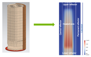
Figure 2: 2D ring model of the HTTF.
In the model, it is assumed that the HTTF was operated at full power of 2.2 MW although this was not achieved in actual experiments, and that axial heating profile is uniform. Inlet helium temperature approximating MHTGR condition is specified. The helium flow rate is chosen so that its temperature increases ~420 K after passing through the core, as is typical in MHTGR. However, the HTTF was not designed to operate at the high pressure encountered in MHTGR, a pressure about the MHTGR nominal pressure is specified. The heat transfer boundary condition for the reactor pressure vessel is established by specifying water flow rate and inlet temperature for the RCCS. The operating conditions for steady state simulation are given in Table 1.
Table 1: Steady state operating conditions.
| Parameter | Unit | Value |
|---|---|---|
| Heating power | 2.2 | |
| Helium mass flow rate | 1.0 | |
| Helium inlet temperature | 500 | |
| Helium pressure | 0.7 | |
| RCCS water mass flow rate | 1.0 | |
| RCCS water inlet temperature | 313.15 | |
| RCCS water pressure | 0.1 | |
| RCCS cavity air flow rate | 0.025 | |
| RCCS air inlet temperature | 300 |
Input File Description
SAM uses a block-structured input syntax. Each block begins with square brackets which contain the type of input and ends with empty square brackets. Each block may contain sub-blocks. The blocks are described in the order as they appear in the input file.
Global Parameters
This block contains the parameters such as global initial pressure, velocity, and temperature conditions, the scaling factors for primary variable residuals, etc. This block also contains a sub-block PBModelParams which specifies the modeling parameters associated with the primitive-variable based fluid model. New users should leave this sub-block unchanged.
For example, to specify global pressure of 7.e5 Pa and temperature of 500 K, the user can input
[GlobalParams]
  SC_HTC = 1.0 # Heat transfer coefficient multiplier, applied to all fluid components
  SC_WF = 1.0 # Wall friction factor multiplier, applied to all fluid components

  global_init_P = 7.e5
  global_init_V = 1.75
  global_init_T = 500
  scaling_factor_var = '1. 1e-3 1e-6'
  use_nearest_node = true
[]
EOS
This block specifies the Equation(s) of State. The users can choose from built-in fluid library for common fluids like air, nitrogen, helium, sodium, molten salts, etc. The users can also input the properties of the fluid as constants or function of temperature. For example, the built-in eos for air can be input as
[EOS]
  [air_eos]
    type = AirEquationOfState
    p_0 = 1.e5 # Pa
  []
[]
MaterialProperties
Material properties are input in this block. The values can be constants or temperature dependent as defined in the Functions block. For example, the properties of stainless steel are input as
[MaterialProperties]
  [ss-mat]
    type = HeatConductionMaterialProps
    k = k304ss
    Cp = cp304ss
    rho = 7.93e3
  []
[]
in which k304ss cp304ss and temperature dependent functions for 304 stainless steel thermal conductivity and specific heat. Note that all units are in SI by default.
Functions
Users can define functions for parameters used in the model. These include temporal, spatial, and temperature dependent functions. For example, users can input enthalpy as a function of temperature, power history as a function of time, or power profile as a function of position. The input below specifies specific heat as a function of temperature.
[Functions]
  [cp304ss]
    #https://www.engineeringtoolbox.com/stainless-steel-specific-heat-thermal-conductivity-vs-temperature-d_2225.html; x- Temperature [K], y-cp [J/kg-K]
    type = PiecewiseLinear
    x = '300 400 600 800 1000    1200    1500'
    y = '477 515 557 582 611     640     682'
  []
[]
Components
This is the main block in the input file. It provides the specifications for all components that make up the core and the RCCS. The inputs for a coolant channel, ceramic, and heater rings in the inner core region are shown below.
  ### Inner core
  [R4] # inner core coolant channel
    type = PBOneDFluidComponent
    input_parameters = CoolantChannel
    position = '${R4_rad} 0 0.3962'
    A = ${R4_area}
    Dh = ${Dh_R4}
  []

  [R5] # inner core ceramic
    type = PBCoupledHeatStructure
    input_parameters = Ceramic
    width_of_hs = ${R5_thi}
    radius_i = ${R5_rad}
    HS_BC_type = 'Coupled Adiabatic'
    HT_surface_area_density_left = ${aw_R4}
    name_comp_left = R4
    HT_area_multiplier_left = ${mult_5}
  []
[Components]
  [R6]
    # inner core heater rods
    type = PBCoupledHeatStructure
    input_parameters = HeaterRods
    width_of_hs = ${R6_thi}
    radius_i = ${R6_rad}
    HS_BC_type = 'Adiabatic Adiabatic'
    hs_power = ${power_R6}
    hs_power_shape_fn = power_fn
  []
[]
Adjacent ceramic rings are coupled using SurfaceCoupling to maintain temperature continuity. For example, coupling between rings 17 and 19 is input as
[Components]
  [Coupling_17_19]
    type = SurfaceCoupling
    use_displaced_mesh = true
    coupling_type = GapHeatTransfer
    surface1_name = 'R17:outer_wall'
    surface2_name = 'R19:inner_wall'
    radius_1 = ${R18_rad}
    h_gap = ${h_gap}
  []
[]
Likewise, a lower reflector ceramic block in contact with a core block is modeled as
[Components]
  [LRCore_R15]
    type = SurfaceCoupling
    use_displaced_mesh = true
    coupling_type = GapHeatTransfer
    surface1_name = 'RL15:top_wall'
    surface2_name = 'R15:bottom_wall'
    h_gap = ${h_gap}
  []
[]
Pipings are modeled as one-dimensional fluid flow component, PBOneDFluidComponent. Their locations are specified with variables position and orientation. Flow area, hydraulic diameter, and pipe length are the main variables that define the element. An example of a pipe that models the air flow in the RCCS cavity is given below
[Components]
  [pipe2]
    #
    type = PBOneDFluidComponent
    position = '${R54_rad} 0 3.7734'
    orientation = '0 0 1'
    f = 0.01
    Dh = 0.1
    length = 1
    A = 0.007854
    initial_P = 1.E+05
    initial_T = 300.
    initial_V = 3.
    n_elems = 10
    eos = air_eos
  []
[]
Fluid components are connected using PBSingleJunction, or PBBranch. For example, connecting the coolant channel of ring 2 in the lower reflector region to the coolant channel in the heated core region is established as
[Components]
  [LRCore_R2]
    type = PBSingleJunction
    inputs = 'RL2(out)'
    outputs = 'R2(in)'
    eos = eos
  []
[]
Boundary conditions can be specified using PBTDV or PBTDJ, such as
[Components]
  [inlet_bc]
    type = PBTDJ
    eos = eos
    T_fn = T_in
    v_fn = v_in
    input = 'inpipe(in)'
  []
[]
[Components]
  [outlet_bc]
    type = PBTDV
    eos = eos
    p_bc = 7.E+05
    input = 'outpipe(out)'
  []
[]
Postprocessors
This block is used to specify the output variables written to a csv file that can be further processed in Excel. For example, to output the exit temperature, mass flow rate, and flow velocity from ring 2
  [R2C_T_out]
    type = ComponentBoundaryVariableValue
    variable = temperature
    input = RL2(in)
  []
  [R2C_T_in]
    type = ComponentBoundaryVariableValue
    variable = temperature
    input = RU2(out)
  []
  [R2C_F]
    type = ComponentBoundaryFlow
    input = RU2(out)
  []
  [R2C_V_in]
    type = ComponentBoundaryVariableValue
    variable = velocity
    input = RU2(out)
  []
Preconditioning
This block describes the preconditioner used by the solver. New users can leave this block unchanged.
Executioner
This block describes the calculation process flow. The users can specify the start time, end time, time step size for the simulation. Other inputs in this block include PETSc solver options, convergence tolerance, quadrature for elements, etc which can be left unchanged.
Output Files Description and Results
There are three types of output files:
HTTF-SS.csv: this is a csv file that writes the user-specified scalar and vector variables to a comma-separated-values file. The data can be imported to Excel for further processing.
HTTF-SS_checkpoint_cp: this is a sub-folder that save snapshots of the simulation data including all meshes, solutions. Users can restart the run from where it ended using the file in the checkpoint folder.
HTTF-SS_out.displaced.e: this is a ExodusII file that has all mesh and solution data. Users can use Paraview to open this .e file to visualize, plot, and analyze the data.
Results
Table 2 tabulates the SAM results (Hua et al., 2023) for flow distribution in different core regions and the associated number of coolant channels in each region. The bypass flow in the central and outer reflectors amounts to 12.3% of total flow which is representative of bypass flow in MHTGR. The helium temperature in each of the 13 coolant rings at blocks 1, 3, and 5 are shown in Figure 3. The temperature increases as helium flows downward from top to bottom (block 1 is the bottom heated core block, block 10 is at the top).
Table 2: Steady-state flow distribution in the HTTF core.
| - | Central Reflector | Inner Core | Middle Core | Outer Core | Outer Reflector |
|---|---|---|---|---|---|
| No. of coolant channels | 6 | 138 | 144 | 234 | 36 |
| Flow () | 0.027 | 0.233 | 0.310 | 0.334 | 0.096 |
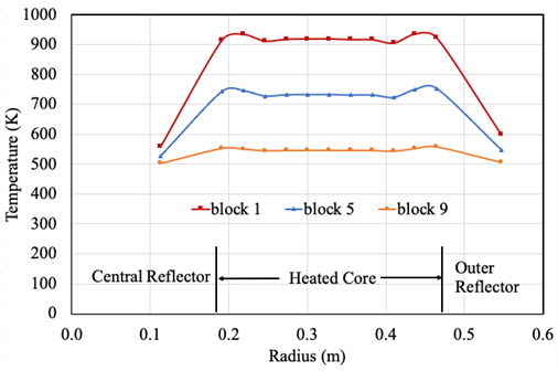
Figure 3: Helium temperature in the 13 coolant rings.
Running the Input File
SAM can be run in Linux, Unix, and MacOS. Due to its dependence on MOOSE, SAM is not compatible with Windows machine. SAM can be run from the shell prompt as shown below.
sam-opt -i httf-ss.i
References
- I. Gutowska and B. Woods.
OSU High Temperature Test Facility Design Technical Report.
Technical Report OSU-HTTF-TECH-003-R2, Oregon State University, Corvallis, OR, 2019.
URL: https://www.osti.gov/biblio/1599410.[BibTeX]
@techreport{Gutowska2019, author = "Gutowska, I. and Woods, B.", address = "Corvallis, OR", institution = "Oregon State University", number = "OSU-HTTF-TECH-003-R2", title = "{OSU High Temperature Test Facility Design Technical Report}", url = "https://www.osti.gov/biblio/1599410", year = "2019" } - R. Hu, L. Zou, G. Hu, D. Nunez, T. Mui, and T. Fei.
SAM Theory Manual.
Technical Report ANL/NE-17/4 Rev. 1, Argonne National Laboratory, Lemont, IL, 2021.[BibTeX]
@techreport{Hu2021, author = "Hu, R. and Zou, L. and Hu, G. and Nunez, D. and Mui, T. and Fei, T.", address = "Lemont, IL", number = "ANL/NE-17/4 Rev. 1", institution = "Argonne National Laboratory", title = "{SAM Theory Manual}", year = "2021" } - Thanh Hua, Ling Zou, and Rui Hu.
SAM model of the HTTF in the virtual test bed.
In Transactions of 2023 ANS Winter Meeting. Washington D.C., 2023. American Nuclear Society.[BibTeX]
@inproceedings{Hua2023, author = "Hua, Thanh and Zou, Ling and Hu, Rui", address = "Washington D.C.", booktitle = "Transactions of 2023 ANS Winter Meeting", publisher = "American Nuclear Society", title = "{SAM model of the HTTF in the virtual test bed}", year = "2023" } - OECD/NEA.
Thermal hydraulic code validation benchmark for high temperature gas-cooled reactors using HTTF data (HTGR T/H).
2023.
URL: https://www.oecd-nea.org/jcms/pl_71708/thermal-hydraulic-code-validation-benchmark-for-high-temperature-gas-cooled-reactors-using-httf-data-htgr-t/h (visited on 2023-09-11).[BibTeX]
@misc{OECD_NEA2023,
    author = "OECD/NEA",
    title = "{Thermal hydraulic code validation benchmark for high temperature gas-cooled reactors using HTTF data (HTGR T/H)}",
    url = "https://www.oecd-nea.org/jcms/pl\_71708/thermal-hydraulic-code-validation-benchmark-for-high-temperature-gas-cooled-reactors-using-httf-data-htgr-t/h",
    urldate = "2023-09-11",
    year = "2023"
}
(htgr/httf/sam_ring_model/HTTF-SS.i)
# ==============================================================================
# High Temperature Transient Facility
# HTTF benchmark PCC Exercise 1A
# SAM input file
# Model: Steady state (null)
# ------------------------------------------------------------------------------
# ANL, 09/2023
# Author(s): Dr. Thanh Hua
# If using or referring to this model, please cite as explained in
# https://mooseframework.inl.gov/virtual_test_bed/citing.html
# ==============================================================================
### Sensitivity coefficients for perturbation
[GlobalParams]
SC_HTC = 1.0 # Heat transfer coefficient multiplier, applied to all fluid components
SC_WF = 1.0 # Wall friction factor multiplier, applied to all fluid components
[]
SC_Power = 1.0 # Initial power sensitivity coefficient
SC_T_inlet = 1.0 # Inlet temperature sensitivity coefficient
SC_v_inlet = 1.0 # Inlet velocity sensitivity coefficient
SC_h_gap = 1.0 # Gap conductance sensitivity coefficient
### Geometry and model parameters
# SS 2.2 MW, 1 kg/s He, Tin = 500 K, 0.7 MPa; RCCS water 1 kg/s 313.2 K,
# 0.25 kg/s air flow in cavity
# 11 coolant rings and 10 heater rings in heated core, the heater rings are rearranged and rods redistributed in order to match heat received by coolant channels
# includes gap heat transfer to account for heat conductance in gaps in R48, R50, and R52
emissivity_GC94 = 0.581
emissivity_SiC = 0.721
emissivity_graphite = 0.90
emissivity_barrel = 0.074
emissivity_vessel = 0.25
emissivity_rccs = 0.074
power_R6 = ${fparse SC_Power * 125714.3}
power_R10 = ${fparse SC_Power * 104761.9}
power_R14 = ${fparse SC_Power * 272381.0}
power_R18 = ${fparse SC_Power * 167619.0}
power_R22 = ${fparse SC_Power * 272381.0}
power_R26 = ${fparse SC_Power * 230476.2}
power_R30 = ${fparse SC_Power * 335238.1}
power_R34 = ${fparse SC_Power * 209523.8}
power_R38 = ${fparse SC_Power * 272381.0}
power_R42 = ${fparse SC_Power * 209523.8}
aw_R2 = 104.987
aw_R4 = 193.822
aw_R8 = 148.633
aw_R12 = 125.984
aw_R16 = 125.984
aw_R20 = 125.984
aw_R24 = 125.984
aw_R28 = 125.984
aw_R32 = 128.317
aw_R36 = 130.329
aw_R40 = 163.952
aw_R44 = 209.974
aw_R46 = 125.984
aw_R52 = 17.498
aw_R54_left = 1.50 #1.96
aw_R54_right = 2.42 #1.96
aw_R56 = 99.481
Dh_R2 = 0.019050
Dh_R4 = 0.010319
Dh_R8 = 0.013456
Dh_R12 = 0.015875
Dh_R16 = 0.015875
Dh_R20 = 0.015875
Dh_R24 = 0.015875
Dh_R28 = 0.015875
Dh_R32 = 0.015586
Dh_R36 = 0.015346
Dh_R40 = 0.012199
Dh_R44 = 0.009525
Dh_R46 = 0.015586
Dh_R52 = 0.114300
Dh_R56 = 0.020000
mult_1 = 0.253
mult_3left = 0.247
mult_3right = 0.398
mult_5 = 0.394
mult_7 = 0.457
mult_9 = 0.451
mult_11 = 0.581
mult_13 = 0.570
mult_15 = 0.610
mult_17 = 0.599
mult_19 = 0.554
mult_21 = 0.546
mult_23 = 0.581
mult_25 = 0.573
mult_27 = 0.603
mult_29 = 0.595
mult_31 = 0.548
mult_33 = 0.542
mult_35 = 0.558
mult_37 = 0.552
mult_39 = 0.414
mult_41 = 0.411
mult_43 = 0.307
mult_45left = 0.307
mult_45right = 0.261
mult_47 = 0.260
#R1_rad = 0.00000
R2_rad = 0.11317
R3_rad = 0.11555
R4_rad = 0.19133
R5_rad = 0.19338
R6_rad = 0.20367
R7_rad = 0.20837
R8_rad = 0.21867
R9_rad = 0.22172
R10_rad = 0.23214
R11_rad = 0.23559
R12_rad = 0.24600
R13_rad = 0.25057
R14_rad = 0.25795
R15_rad = 0.26596
R16_rad = 0.27333
R17_rad = 0.27813
R18_rad = 0.28717
R19_rad = 0.29163
R20_rad = 0.30067
R21_rad = 0.30504
R22_rad = 0.31321
R23_rad = 0.31983
R24_rad = 0.32800
R25_rad = 0.33258
R26_rad = 0.34138
R27_rad = 0.34654
R28_rad = 0.35533
R29_rad = 0.36009
R30_rad = 0.36791
R31_rad = 0.37485
R32_rad = 0.38267
R33_rad = 0.38691
R34_rad = 0.39643
R35_rad = 0.40048
R36_rad = 0.41000
R37_rad = 0.41426
R38_rad = 0.421
R39_rad = 0.42595
R40_rad = 0.43734
R41_rad = 0.43985
R42_rad = 0.453
R43_rad = 0.45655
R44_rad = 0.46467
R45_rad = 0.46613
R46_rad = 0.54682
R47_rad = 0.54889
#R48_rad = 0.59345
R49_rad = 0.60188
R50_rad = 0.75088
R51_rad = 0.757238
R52_rad = 0.7620
R53_rad = 0.81915
R54_rad = 0.83185
R55_rad = 1.34185
R56_rad = 1.34385
R1_thi = 0.11317
R3_thi = 0.07579
R5_thi = 0.01030
R6_thi = 0.00470
R7_thi = 0.01030
R9_thi = 0.01041
R10_thi = 0.00345
R11_thi = 0.01041
R13_thi = 0.00738
R14_thi = 0.00800
R15_thi = 0.00738
R17_thi = 0.00904
R18_thi = 0.00446
R19_thi = 0.00904
R21_thi = 0.00817
R22_thi = 0.00662
R23_thi = 0.00817
R25_thi = 0.00880
R26_thi = 0.00516
R27_thi = 0.00880
R29_thi = 0.00781
R30_thi = 0.00695
R31_thi = 0.00781
R33_thi = 0.00952
R34_thi = 0.00405
R35_thi = 0.00952
R37_thi = 0.00674
R38_thi = 0.00495
R39_thi = 0.01138
R41_thi = 0.01315
R42_thi = 0.00355
R43_thi = 0.00812
R45_thi = 0.08069
R47_thi = 0.04456
R49_thi = 0.14900
R50_thi = 0.006358
R51_thi = 0.004762
R53_thi = 0.0127
R55_thi = 0.002
R2_area = 0.001710138
R4_area = 0.002470199
R8_area = 0.004227841
R12_area = 0.007125574
R16_area = 0.00831317
R20_area = 0.00831317
R24_area = 0.009500765
R28_area = 0.010688361
R32_area = 0.010260826
R36_area = 0.011020888
R40_area = 0.006935559
R44_area = 0.004275344
R46_area = 0.007125574
R56_area = 0.08475
h_gap = ${fparse SC_h_gap * 1.e5}
#h_gapR52 = 3.95 #k/d = 0.22 / 0.05715 k evaluated at 500 K
#h_gapR50 = 39.32 #k/d = 0.25 / 0.006358 k evaluated at 600 K
#h_gapR48 = 27.28 #k/d = 0.23 / 0.008431 k evaluated at 520 K
n_core = 20
n_urlr = 4
[Application]
type = SamApp
[]
### HTTF SAM model
[GlobalParams]
global_init_P = 7.e5
global_init_V = 1.75
global_init_T = 500
scaling_factor_var = '1. 1e-3 1e-6'
use_nearest_node = true
[]
[EOS]
[eos]
type = PTFunctionsEOS
p_0 = 7.e5 # Pa
rho = rhoHe
# beta = beta_fn
cp = cpHe
mu = muHe
k = kHe
enthalpy = HHe
[]
[air_eos]
type = AirEquationOfState
p_0 = 1.e5 # Pa
[]
# [water_eos]
# type = PTFluidPropertiesEOS
# p_0 = 1.e5
# fp = fluid_props2
# []
[water_eos]
type = PTConstantEOS
p_0 = 1e5 # Pa
rho_0 = 998.2 # kg/m^3 at 293.15 K
beta = 0 # K^{-1}
cp = 4184 # at at 293.15 K
h_0 = 500000 # J/kg at 273.15 K
T_0 = 273.15 # K
mu = 1.0014e-3 # Pa-s at 293.15 K
k = 0.598 # W/m-K at 293.15 K
[]
[]
[Functions]
[time_stepper] # Reset timestepper at start of transient
type = PiecewiseConstant
x = '-80000 0 0.05'
y = ' 1e6 0.05 1e6'
direction = left_inclusive
[]
[T_in]
type = PiecewiseLinear
x = '0 1.e6'
y = '500 500'
scale_factor = ${SC_T_inlet}
[]
[v_in] # PCC event, ramp down from 100% to 0% flow over 2 seconds
type = PiecewiseLinear
x = '-1.e6 0 2 1.e6'
y = ' 1 1 0 0'
scale_factor = ${fparse SC_v_inlet * 21.905}
[]
[T_RCCS_in]
type = PiecewiseLinear
x = '-1.e6 0 60 1.e6'
y = '313.15 313.15 313.15 313.15'
[]
[v_rccs_in] #mdot = 1 kg/s water, v = mdot/rhoA = 1/1000/0.08475
type = PiecewiseLinear
x = '-1.e6 0 60 1.e6'
y = '0.0118 0.0118 0.0118 0.0118'
[]
[heater_axial]
# heater extends from x = 0.3962 to 2.3772
type = PiecewiseLinear
x = '0.3962 2.3772 '
y = '1.0 1.0'
axis = x
[]
[power_history]
# ANS94 standard
type = PiecewiseLinear
x = ' -1.e6 0 0.01 1.5 2 4 6 8 10 15 20
40 60 80 100 150 200 400 600 800 1000
1500 2000 4000 6000 8000 10000 15000 20000 40000 60000
80000 100000 500000 1000000 2000000 3000000 4000000 5000000'
y = ' 1 1 0.05648 0.05494 0.05365 0.04997 0.04753 0.04572 0.0443 0.04172 0.03991
0.03561 0.03312 0.03138 0.03006 0.0278 0.02631 0.02302 0.02113 0.01974 0.01865
0.01662 0.01519 0.01208 0.01062 0.009754 0.009164 0.008013383 0.007321249 0.005889274 0.005185243
0.004737381 0.004416809 0.0026646 0.002143426 0.00172419 0.001518072 0.001386953 0.0012931'
[]
[power_fn]
type = CompositeFunction
functions = 'power_history heater_axial'
[]
[kgc94] #ceramic GC-94F therm. cond; x- Temperature [K], y-Thermal condiuctivity [W/m-K] HTTF Report OSU-HTTF-TECH-003-R2 appendix
type = PiecewiseLinear
x = '478.15 698.15 923.15 1143.15 1368.15 2000.0'
y = '5.25 3.58 2.83 2.49 2.47 2.47'
[]
[rhogc94] #ceramic GC-94F density; x- Temperature [K], y-density [kg/m^3] HTTF Report OSU-HTTF-TECH-003-R2 appendix
type = PiecewiseLinear
x = '378.15 1089.15 1922.15'
y = '3030 2920 2930'
[]
[cpgc94] #ceramic GC-94F heat capacity; x- Temperature [K], y-cp [J/kg-K] HTTF Report OSU-HTTF-TECH-003-R2 appendix
type = PiecewiseLinear
x = '298.15 323.15 373.15 473.1 573.15 673.15 773.15 873.15 973.15 1073.15 1173.15 1273.15
1373.15 1473.15 1573.1 1673.15 1773.15 1873.15'
y = '870 920 1010 1190 1260 1180 1180 1190 1210 1240 1200 1190
1190 1240 1290 1290 3050 1270'
[]
[kgraphite] #G-348 graphite therm. cond; x- Temperature [K], y-Thermal conductivity [W/m-K] correlation in OSU-HTTF-TECH-003-R2 Appendix (which is from INL report)
type = PiecewiseLinear
x = '300 400 500 600 700 800 900 1000 1100 1200 1300 1400 1500 1600 1700 1800 1900 2000'
y = '131.143 120.975 111.550 102.869 94.932 87.739 81.290 75.584 70.622 66.404 62.930 60.200 58.213 56.970 56.471 56.716 57.705 59.437'
[]
[cpgraphite] #G-348 graphite specific heat; x- Temperature [K], y- sp. heat [J/kg-K] Butland and Maddison, J Nucl Mater. 1973/74 (49) 45-56, suggested in OSU-HTTF-TECH-003-R2 Apendix
type = PiecewiseLinear
x = '300 400 500 600 700 800 900 1000 1100 1200 1300 1400 1500 1600 1700 1800 1900 2000'
y = '713.24 991.02 1218.45 1390.79 1520.85 1620.52 1698.40 1760.40 1810.64 1851.96 1886.42 1915.49 1940.26 1961.58 1980.06 1996.20 2010.39 2022.93'
[]
[rhographite] #G-348 graphite density; x- Temperature [K], y- density [kg/m3] OSU-HTTF-TECH-003-R2 Appendix (which is from INL report)
type = PiecewiseLinear
x = '295.75 374.15 472.45 574.75 674.75 774.75 874.75 974.85 1074.45 1173.95 1274.05'
y = '1888.5 1886.3 1883.5 1880.4 1877.2 1873.9 1870.5 1867 1863.4 1859.6 1855.7'
[]
[kSiC80] #SiC-80 therm. cond; x- Temperature [K], y-Thermal condiuctivity [W/m-K] Relap5 input model
type = PiecewiseLinear
x = '250 473 673 873 1073 1573'
y = '7.56 7.56 6.58 6.73 6.95 6.95'
[]
[cpSiC80] #SiC-80 therm. cond; x- Temperature [K], y-Thermal condiuctivity [W/m-K] Relap5 input model
type = PiecewiseLinear
x = '250 327.3 397.9 466.9 534.7 601.6 668 733.8 799.2 864.1 928.4 992.2 1055.7 1118.7 1181.7 1244.1 1306.2 1368.1 1429.9 1573'
y = '750 750 890 970 1020 1070 1100 1130 1140 1160 1170 1180 1180 1210 1210 1220 1210 1110 1220 1220'
[]
[k304ss] #ASM handbook; x- Temperature [K], y-Thermal conductivity [W/m-K]
type = PiecewiseLinear
x = '373 773'
y = '16.2 21.5'
[]
[cp304ss] #https://www.engineeringtoolbox.com/stainless-steel-specific-heat-thermal-conductivity-vs-temperature-d_2225.html; x- Temperature [K], y-cp [J/kg-K]
type = PiecewiseLinear
x = '300 400 600 800 1000 1200 1500'
y = '477 515 557 582 611 640 682'
[]
[rhoHe] #Helium density; x- Temperature [K], y- density [kg/m3]
type = PiecewiseLinear
x = '300 320 340 360 380 400 420 440 460 480 500 520 540 560 580 600 620 640 660 680
700 720 740 760 780 800 820 840 860 880 900 920 940 960 980 1000 1020 1040 1060 1080
1100 1120 1140 1160 1180 1200 1220 1240 1260 1280 1300 1320 1340 1360 1380 1400 1420 1440 1460 1480 1500'
y = '1.1197 1.05 0.9884 0.93365 0.88465 0.84053 0.80061 0.76431 0.73115 0.70075 0.67278 0.64695 0.62304 0.60083 0.58014 0.56084 0.54278 0.52584 0.50993 0.49495
0.48083 0.46749 0.45488 0.44292 0.43158 0.4208 0.41055 0.40079 0.39148 0.38259 0.3741 0.36597 0.35819 0.35074 0.34359 0.33672 0.33012 0.32378 0.31768 0.3118
0.30613 0.30067 0.2954 0.29031 0.2854 0.28064 0.27605 0.2716 0.26729 0.26311 0.25907 0.25515 0.25134 0.24765 0.24406 0.24058 0.23719 0.2339 0.2307 0.22758 0.22455'
[]
[HHe] #Helium Enthalpy; x- Temperature [K], y- denthalpy [j/kg]
type = PiecewiseLinear
x = '300 320 340 360 380 400 420 440 460 480 500 520 540 560 580 600 620 640 660 680
700 720 740 760 780 800 820 840 860 880 900 920 940 960 980 1000 1020 1040 1060 1080
1100 1120 1140 1160 1180 1200 1220 1240 1260 1280 1300 1320 1340 1360 1380 1400 1420 1440 1460 1480 1500'
y = '1565400 1669200 1773100 1876900 1980800 2084600 2188500 2292300 2396200 2500000 2603900 2707700 2811600 2915400 3019300 3123100 3227000 3330800 3434700 3538500
3642400 3746200 3850100 3954000 4057800 4161700 4265500 4369400 4473200 4577100 4680900 4784800 4888600 4992500 5096300 5200200 5304100 5407900 5511800 5615600
5719500 5823300 5927200 6031000 6134900 6238800 6342600 6446500 6550300 6654200 6758000 6861900 6965700 7069600 7173500 7277300 7381200 7485000 7588900 7692700 7796600'
[]
[cpHe] #Helium specific heat; x- Temperature [K], y- sp. heat [J/kg-K]
type = PiecewiseLinear
x = '300 320 340 360 380 400 420 440 460 480 500 520 540 560 580 600 620 640 660 680
700 720 740 760 780 800 820 840 860 880 900 920 940 960 980 1000 1020 1040 1060 1080
1100 1120 1140 1160 1180 1200 1220 1240 1260 1280 1300 1320 1340 1360 1380 1400 1420 1440 1460 1480 1500'
y = '5192.5 5192.5 5192.5 5192.5 5192.4 5192.4 5192.4 5192.5 5192.5 5192.5 5192.5 5192.5 5192.5 5192.5 5192.5 5192.5 5192.6 5192.6 5192.6 5192.6
5192.6 5192.6 5192.6 5192.6 5192.6 5192.7 5192.7 5192.7 5192.7 5192.7 5192.7 5192.7 5192.7 5192.7 5192.7 5192.7 5192.7 5192.8 5192.8 5192.8
5192.8 5192.8 5192.8 5192.8 5192.8 5192.8 5192.8 5192.8 5192.8 5192.8 5192.8 5192.8 5192.8 5192.8 5192.8 5192.8 5192.8 5192.8 5192.9 5192.9 5192.9'
[]
[muHe] #Helium viscosity; x- Temperature [K], y-viscosity [Pa.s]
type = PiecewiseLinear
x = '300 320 340 360 380 400 420 440 460 480 500 520 540 560 580 600 620 640 660 680
700 720 740 760 780 800 820 840 860 880 900 920 940 960 980 1000 1020 1040 1060 1080
1100 1120 1140 1160 1180 1200 1220 1240 1260 1280 1300 1320 1340 1360 1380 1400 1420 1440 1460 1480 1500'
y = '0.000019951 0.00002085 0.000021735 0.000022605 0.000023463 0.000024308 0.000025142 0.000025965 0.000026778 0.000027581 0.000028376 0.000029161 0.000029939 0.000030708 0.000031471 0.000032226 0.000032974 0.000033715 0.000034451 0.00003518
0.000035903 0.000036621 0.000037333 0.00003804 0.000038742 0.000039438 0.00004013 0.000040818 0.000041501 0.000042179 0.000042854 0.000043524 0.00004419 0.000044853 0.000045511 0.000046166 0.000046817 0.000047465 0.000048109 0.00004875
0.000049388 0.000050022 0.000050654 0.000051282 0.000051907 0.00005253 0.000053149 0.000053766 0.00005438 0.000054991 0.0000556 0.000056206 0.000056809 0.00005741 0.000058009 0.000058605 0.000059198 0.00005979 0.000060379 0.000060966 0.000061551'
[]
[kHe] #Helium therm. cond; x- Temperature [K], y-Thermal condiuctivity [W/m-K]
type = PiecewiseLinear
x = '300 320 340 360 380 400 420 440 460 480 500 520 540 560 580 600 620 640 660 680
700 720 740 760 780 800 820 840 860 880 900 920 940 960 980 1000 1020 1040 1060 1080
1100 1120 1140 1160 1180 1200 1220 1240 1260 1280 1300 1320 1340 1360 1380 1400 1420 1440 1460 1480 1500'
y = '0.15643 0.16354 0.17053 0.17739 0.18415 0.1908 0.19736 0.20382 0.2102 0.2165 0.22272 0.22887 0.23495 0.24096 0.24691 0.2528 0.25864 0.26442 0.27014 0.27582
0.28144 0.28702 0.29256 0.29805 0.30349 0.3089 0.31427 0.3196 0.32489 0.33014 0.33536 0.34055 0.3457 0.35082 0.35591 0.36097 0.366 0.371 0.37597 0.38091
0.38583 0.39072 0.39558 0.40042 0.40524 0.41003 0.4148 0.41954 0.42426 0.42896 0.43364 0.4383 0.44294 0.44755 0.45215 0.45672 0.46128 0.46582 0.47034 0.47484 0.47932'
[]
[h_gapR48]
type = PiecewiseLinear
x = '300 350 400 450 500 550 600 650 700 750 800 850 900 950 1000'
y = '18.55 20.63 22.63 24.55 26.42 28.22 29.98 31.70 33.38 35.03 36.64 38.22 39.78 41.31 42.81'
[]
[h_gapR50]
type = PiecewiseLinear
x = '300 350 400 450 500 550 600 650 700 750 800 850 900 950 1000'
y = '24.60 27.36 30.01 32.56 35.03 37.43 39.76 42.04 44.27 46.45 48.58 50.68 52.75 54.78 56.77'
[]
[h_gapR52]
type = PiecewiseLinear
x = '300 350 400 450 500 550 600 650 700 750 800 850 900 950 1000'
y = '2.74 3.04 3.34 3.62 3.90 4.16 4.42 4.68 4.92 5.17 5.41 5.64 5.87 6.09 6.32'
[]
[beta_fn]
type = PiecewiseLinear
x = '300 2000'
y = '0 0'
[]
[]
[MaterialProperties]
[ss-mat]
type = HeatConductionMaterialProps
k = k304ss
Cp = cp304ss
rho = 7.93e3
[]
[graphite-mat]
type = SolidMaterialProps
k = kgraphite
Cp = cpgraphite
rho = rhographite
[]
[GC-94F]
type = SolidMaterialProps
k = kgc94
Cp = cpgc94
rho = rhogc94
[]
[SiC-80]
type = SolidMaterialProps
k = kSiC80
Cp = cpSiC80
rho = 2370.0 # OSU-HTTF-TECH-003-R2 Appendix
[]
[fluid_props2]
type = Water97FluidProperties
[]
[]
[ComponentInputParameters]
[CoolantChannel]
type = PBOneDFluidComponentParameters
orientation = '0 0 1'
eos = eos
length = 1.981
HTC_geometry_type = Pipe
n_elems = ${n_core}
initial_V = -15.00
# initial_T = 800
[]
[Ceramic]
type = HeatStructureParameters
position = '0 0 0.3962'
orientation = '0 0 1'
hs_type = cylinder
length = 1.981
elem_number_radial = 5
elem_number_axial = ${n_core}
dim_hs = 2
material_hs = 'GC-94F'
# Ts_init = 900
[]
[HeaterRods]
type = HeatStructureParameters
position = '0 0 0.3962'
orientation = '0 0 1'
hs_type = cylinder
length = 1.981
elem_number_radial = 5
elem_number_axial = ${n_core}
dim_hs = 2
material_hs = 'graphite-mat'
# Ts_init = 900
[]
[UR-CoolantChannel]
type = PBOneDFluidComponentParameters
orientation = '0 0 1'
eos = eos
length = 0.3962
HTC_geometry_type = Pipe
n_elems = ${n_urlr}
initial_V = -15.00
# initial_T = 900
[]
[UR-Ceramic]
type = HeatStructureParameters
position = '0 0 2.3772'
orientation = '0 0 1'
hs_type = cylinder
length = 0.3962
elem_number_radial = 5
elem_number_axial = ${n_urlr}
dim_hs = 2
material_hs = 'GC-94F'
# Ts_init = 900
[]
[LR-CoolantChannel]
type = PBOneDFluidComponentParameters
orientation = '0 0 1'
eos = eos
length = 0.3962
HTC_geometry_type = Pipe
n_elems = ${n_urlr}
initial_V = -15.00
# initial_T = 600
[]
[LR-Ceramic]
type = HeatStructureParameters
position = '0 0 0'
orientation = '0 0 1'
hs_type = cylinder
length = 0.3962
elem_number_radial = 5
elem_number_axial = ${n_urlr}
dim_hs = 2
material_hs = 'GC-94F'
# Ts_init = 600
[]
[]
[Components]
####################### CORE ##############################
### Central reflector
[R1] # central reflector ceramic
type = PBCoupledHeatStructure
input_parameters = Ceramic
width_of_hs = ${R1_thi}
radius_i = 0.
HS_BC_type = 'Adiabatic Coupled'
HT_surface_area_density_right = ${aw_R2}
name_comp_right = R2
HT_area_multiplier_right = ${mult_1}
[]
[R2] # central reflector coolant channel
type = PBOneDFluidComponent
input_parameters = CoolantChannel
position = '${R2_rad} 0 0.3962'
A = ${R2_area}
Dh = ${Dh_R2}
[]
[R3] # central reflector ceramic
type = PBCoupledHeatStructure
input_parameters = Ceramic
width_of_hs = ${R3_thi}
radius_i = ${R3_rad}
HS_BC_type = 'Coupled Coupled'
HT_surface_area_density_left = ${aw_R2}
HT_surface_area_density_right = ${aw_R4}
name_comp_left = R2
name_comp_right = R4
HT_area_multiplier_left = ${mult_3left}
HT_area_multiplier_right = ${mult_3right}
[]
### Inner core
[R4] # inner core coolant channel
type = PBOneDFluidComponent
input_parameters = CoolantChannel
position = '${R4_rad} 0 0.3962'
A = ${R4_area}
Dh = ${Dh_R4}
[]
[R5] # inner core ceramic
type = PBCoupledHeatStructure
input_parameters = Ceramic
width_of_hs = ${R5_thi}
radius_i = ${R5_rad}
HS_BC_type = 'Coupled Adiabatic'
HT_surface_area_density_left = ${aw_R4}
name_comp_left = R4
HT_area_multiplier_left = ${mult_5}
[]
[R6_Hegap1] # He gap surrounding graphite rods
type = SurfaceCoupling
use_displaced_mesh = true
coupling_type = RadiationHeatTransfer
surface1_name = 'R5:outer_wall'
surface2_name = 'R6:inner_wall'
epsilon_1 = ${emissivity_GC94}
epsilon_2 = ${emissivity_graphite}
radius_1 = ${R6_rad}
[]
[R6] # inner core heater rods
type = PBCoupledHeatStructure
input_parameters = HeaterRods
width_of_hs = ${R6_thi}
radius_i = ${R6_rad}
HS_BC_type = 'Adiabatic Adiabatic'
hs_power = ${power_R6}
hs_power_shape_fn = power_fn
[]
[R6_Hegap2] # He gap surrounding graphite rods
type = SurfaceCoupling
use_displaced_mesh = true
coupling_type = RadiationHeatTransfer
surface1_name = 'R6:outer_wall'
surface2_name = 'R7:inner_wall'
epsilon_1 = ${emissivity_graphite}
epsilon_2 = ${emissivity_GC94}
radius_1 = ${R7_rad}
[]
[R7] # inner core ceramic
type = PBCoupledHeatStructure
input_parameters = Ceramic
width_of_hs = ${R7_thi}
radius_i = ${R7_rad}
HS_BC_type = 'Adiabatic Coupled'
HT_surface_area_density_right = ${aw_R8}
name_comp_right = R8
HT_area_multiplier_right = ${mult_7}
[]
[R8] # inner core coolant channel
type = PBOneDFluidComponent
input_parameters = CoolantChannel
position = '${R8_rad} 0 0.3962'
A = ${R8_area}
Dh = ${Dh_R8}
[]
[R9] # inner core ceramic
type = PBCoupledHeatStructure
input_parameters = Ceramic
width_of_hs = ${R9_thi}
radius_i = ${R9_rad}
HS_BC_type = 'Coupled Adiabatic'
HT_surface_area_density_left = ${aw_R8}
name_comp_left = R8
HT_area_multiplier_left = ${mult_9}
[]
[R10_Hegap1] # He gap surrounding graphite rods
type = SurfaceCoupling
use_displaced_mesh = true
coupling_type = RadiationHeatTransfer
surface1_name = 'R9:outer_wall'
surface2_name = 'R10:inner_wall'
epsilon_1 = ${emissivity_GC94}
epsilon_2 = ${emissivity_graphite}
radius_1 = ${R10_rad}
[]
[R10] # inner core heater rods
type = PBCoupledHeatStructure
input_parameters = HeaterRods
width_of_hs = ${R10_thi}
radius_i = ${R10_rad}
HS_BC_type = 'Adiabatic Adiabatic'
hs_power = ${power_R10}
hs_power_shape_fn = power_fn
[]
[R10_Hegap2] # He gap surrounding graphite rods
type = SurfaceCoupling
use_displaced_mesh = true
coupling_type = RadiationHeatTransfer
surface1_name = 'R10:outer_wall'
surface2_name = 'R11:inner_wall'
epsilon_1 = ${emissivity_graphite}
epsilon_2 = ${emissivity_GC94}
radius_1 = ${R11_rad}
[]
[R11] # inner core ceramic
type = PBCoupledHeatStructure
input_parameters = Ceramic
width_of_hs = ${R11_thi}
radius_i = ${R11_rad}
HS_BC_type = 'Adiabatic Coupled'
HT_surface_area_density_right = ${aw_R12}
name_comp_right = R12
HT_area_multiplier_right = ${mult_11}
[]
[R12] # inner core coolant channel
type = PBOneDFluidComponent
input_parameters = CoolantChannel
position = '${R12_rad} 0 0.3962'
A = ${R12_area}
Dh = ${Dh_R12}
[]
[R13] # inner core ceramic
type = PBCoupledHeatStructure
input_parameters = Ceramic
width_of_hs = ${R13_thi}
radius_i = ${R13_rad}
HS_BC_type = 'Coupled Adiabatic'
HT_surface_area_density_left = ${aw_R12}
name_comp_left = R12
HT_area_multiplier_left = ${mult_13}
[]
[R14_Hegap1] # He gap surrounding graphite rods
type = SurfaceCoupling
use_displaced_mesh = true
coupling_type = RadiationHeatTransfer
surface1_name = 'R13:outer_wall'
surface2_name = 'R14:inner_wall'
epsilon_1 = ${emissivity_GC94}
epsilon_2 = ${emissivity_graphite}
radius_1 = ${R14_rad}
[]
[R14] # inner core heater rods
type = PBCoupledHeatStructure
input_parameters = HeaterRods
width_of_hs = ${R14_thi}
radius_i = ${R14_rad}
HS_BC_type = 'Adiabatic Adiabatic'
hs_power = ${power_R14}
hs_power_shape_fn = power_fn
[]
[R14_Hegap2] # He gap surrounding graphite rods
type = SurfaceCoupling
use_displaced_mesh = true
coupling_type = RadiationHeatTransfer
surface1_name = 'R14:outer_wall'
surface2_name = 'R15:inner_wall'
epsilon_1 = ${emissivity_graphite}
epsilon_2 = ${emissivity_GC94}
radius_1 = ${R15_rad}
[]
[R15] # inner core ceramic
type = PBCoupledHeatStructure
input_parameters = Ceramic
width_of_hs = ${R15_thi}
radius_i = ${R15_rad}
HS_BC_type = 'Adiabatic Coupled'
HT_surface_area_density_right = ${aw_R16}
name_comp_right = R16
HT_area_multiplier_right = ${mult_15}
[]
[R16] # middle core coolant channel
type = PBOneDFluidComponent
input_parameters = CoolantChannel
position = '${R16_rad} 0 0.3962'
A = ${R16_area}
Dh = ${Dh_R16}
[]
[R17] # inner core ceramic
type = PBCoupledHeatStructure
input_parameters = Ceramic
width_of_hs = ${R17_thi}
radius_i = ${R17_rad}
HS_BC_type = 'Coupled Adiabatic'
HT_surface_area_density_left = ${aw_R16}
name_comp_left = R16
HT_area_multiplier_left = ${mult_17}
[]
[R18_Hegap1] # He gap surrounding graphite rods
type = SurfaceCoupling
use_displaced_mesh = true
coupling_type = RadiationHeatTransfer
surface1_name = 'R17:outer_wall'
surface2_name = 'R18:inner_wall'
epsilon_1 = ${emissivity_GC94}
epsilon_2 = ${emissivity_graphite}
radius_1 = ${R18_rad}
[]
[R18] # inner core heater rods
type = PBCoupledHeatStructure
input_parameters = HeaterRods
width_of_hs = ${R18_thi}
radius_i = ${R18_rad}
HS_BC_type = 'Adiabatic Adiabatic'
hs_power = ${power_R18}
hs_power_shape_fn = power_fn
[]
[R18_Hegap2] # He gap surrounding graphite rods
type = SurfaceCoupling
use_displaced_mesh = true
coupling_type = RadiationHeatTransfer
surface1_name = 'R18:outer_wall'
surface2_name = 'R19:inner_wall'
epsilon_1 = ${emissivity_graphite}
epsilon_2 = ${emissivity_GC94}
radius_1 = ${R19_rad}
[]
[R19] # middle core ceramic
type = PBCoupledHeatStructure
input_parameters = Ceramic
width_of_hs = ${R19_thi}
radius_i = ${R19_rad}
HS_BC_type = 'Adiabatic Coupled'
HT_surface_area_density_right = ${aw_R20}
name_comp_right = R20
HT_area_multiplier_right = ${mult_19}
[]
## Middle core ##
[R20] # middle core coolant channel
type = PBOneDFluidComponent
input_parameters = CoolantChannel
position = '${R20_rad} 0 0.3962'
A = ${R20_area}
Dh = ${Dh_R20}
[]
[R21] # middle core ceramic
type = PBCoupledHeatStructure
input_parameters = Ceramic
width_of_hs = ${R21_thi}
radius_i = ${R21_rad}
HS_BC_type = 'Coupled Adiabatic'
HT_surface_area_density_left = ${aw_R20}
name_comp_left = R20
HT_area_multiplier_left = ${mult_21}
[]
[R22_Hegap1] # He gap surrounding graphite rods
type = SurfaceCoupling
use_displaced_mesh = true
coupling_type = RadiationHeatTransfer
surface1_name = 'R21:outer_wall'
surface2_name = 'R22:inner_wall'
epsilon_1 = ${emissivity_GC94}
epsilon_2 = ${emissivity_graphite}
radius_1 = ${R22_rad}
[]
[R22] # middle core heater rods
type = PBCoupledHeatStructure
input_parameters = HeaterRods
width_of_hs = ${R22_thi}
radius_i = ${R22_rad}
HS_BC_type = 'Adiabatic Adiabatic'
hs_power = ${power_R22}
hs_power_shape_fn = power_fn
[]
[R22_Hegap2] # He gap surrounding graphite rods
type = SurfaceCoupling
use_displaced_mesh = true
coupling_type = RadiationHeatTransfer
surface1_name = 'R22:outer_wall'
surface2_name = 'R23:inner_wall'
epsilon_1 = ${emissivity_graphite}
epsilon_2 = ${emissivity_GC94}
radius_1 = ${R23_rad}
[]
[R23] # middle core ceramic
type = PBCoupledHeatStructure
input_parameters = Ceramic
width_of_hs = ${R23_thi}
radius_i = ${R23_rad}
HS_BC_type = 'Adiabatic Coupled'
HT_surface_area_density_right = ${aw_R24}
name_comp_right = R24
HT_area_multiplier_right = ${mult_23}
[]
[R24] # middle core coolant channel
type = PBOneDFluidComponent
input_parameters = CoolantChannel
position = '${R24_rad} 0 0.3962'
A = ${R24_area}
Dh = ${Dh_R24}
[]
[R25] # middle core ceramic
type = PBCoupledHeatStructure
input_parameters = Ceramic
width_of_hs = ${R25_thi}
radius_i = ${R25_rad}
HS_BC_type = 'Coupled Adiabatic'
HT_surface_area_density_left = ${aw_R24}
name_comp_left = R24
HT_area_multiplier_left = ${mult_25}
[]
[R26_Hegap1] # He gap surrounding graphite rods
type = SurfaceCoupling
use_displaced_mesh = true
coupling_type = RadiationHeatTransfer
surface1_name = 'R25:outer_wall'
surface2_name = 'R26:inner_wall'
epsilon_1 = ${emissivity_GC94}
epsilon_2 = ${emissivity_graphite}
radius_1 = ${R26_rad}
[]
[R26] # middle core heater rods
type = PBCoupledHeatStructure
input_parameters = HeaterRods
width_of_hs = ${R26_thi}
radius_i = ${R26_rad}
HS_BC_type = 'Adiabatic Adiabatic'
hs_power = ${power_R26}
hs_power_shape_fn = power_fn
[]
[R26_Hegap2] # He gap surrounding graphite rods
type = SurfaceCoupling
use_displaced_mesh = true
coupling_type = RadiationHeatTransfer
surface1_name = 'R26:outer_wall'
surface2_name = 'R27:inner_wall'
epsilon_1 = ${emissivity_graphite}
epsilon_2 = ${emissivity_GC94}
radius_1 = ${R27_rad}
[]
[R27] # middle core ceramic
type = PBCoupledHeatStructure
input_parameters = Ceramic
width_of_hs = ${R27_thi}
radius_i = ${R27_rad}
HS_BC_type = 'Adiabatic Coupled'
HT_surface_area_density_right = ${aw_R28}
name_comp_right = R28
HT_area_multiplier_right = ${mult_27}
[]
[R28] # middle core coolant channel
type = PBOneDFluidComponent
input_parameters = CoolantChannel
position = '${R28_rad} 0 0.3962'
A = ${R28_area}
Dh = ${Dh_R28}
[]
[R29] # middle core ceramic
type = PBCoupledHeatStructure
input_parameters = Ceramic
width_of_hs = ${R29_thi}
radius_i = ${R29_rad}
HS_BC_type = 'Coupled Adiabatic'
HT_surface_area_density_left = ${aw_R28}
name_comp_left = R28
HT_area_multiplier_left = ${mult_29}
[]
[R30_Hegap1] # He gap surrounding graphite rods
type = SurfaceCoupling
use_displaced_mesh = true
coupling_type = RadiationHeatTransfer
surface1_name = 'R29:outer_wall'
surface2_name = 'R30:inner_wall'
epsilon_1 = ${emissivity_GC94}
epsilon_2 = ${emissivity_graphite}
radius_1 = ${R30_rad}
[]
[R30] # middle core heater rods
type = PBCoupledHeatStructure
input_parameters = HeaterRods
width_of_hs = ${R30_thi}
radius_i = ${R30_rad}
HS_BC_type = 'Adiabatic Adiabatic'
hs_power = ${power_R30}
hs_power_shape_fn = power_fn
[]
[R30_Hegap2] # He gap surrounding graphite rods
type = SurfaceCoupling
use_displaced_mesh = true
coupling_type = RadiationHeatTransfer
surface1_name = 'R30:outer_wall'
surface2_name = 'R31:inner_wall'
epsilon_1 = ${emissivity_graphite}
epsilon_2 = ${emissivity_GC94}
radius_1 = ${R31_rad}
[]
[R31] # middle core ceramic
type = PBCoupledHeatStructure
input_parameters = Ceramic
width_of_hs = ${R31_thi}
radius_i = ${R31_rad}
HS_BC_type = 'Adiabatic Coupled'
HT_surface_area_density_right = ${aw_R32}
name_comp_right = R32
HT_area_multiplier_right = ${mult_31}
[]
### Outer core
[R32] # outer core coolant channel
type = PBOneDFluidComponent
input_parameters = CoolantChannel
position = '${R32_rad} 0 0.3962'
A = ${R32_area}
Dh = ${Dh_R32}
[]
[R33] # outer core ceramic
type = PBCoupledHeatStructure
input_parameters = Ceramic
width_of_hs = ${R33_thi}
radius_i = ${R33_rad}
HS_BC_type = 'Coupled Adiabatic'
HT_surface_area_density_left = ${aw_R32}
name_comp_left = R32
HT_area_multiplier_left = ${mult_33}
[]
[R34_Hegap1] # He gap surrounding graphite rods
type = SurfaceCoupling
use_displaced_mesh = true
coupling_type = RadiationHeatTransfer
surface1_name = 'R33:outer_wall'
surface2_name = 'R34:inner_wall'
epsilon_1 = ${emissivity_GC94}
epsilon_2 = ${emissivity_graphite}
radius_1 = ${R34_rad}
[]
[R34] # outer core heater rods
type = PBCoupledHeatStructure
input_parameters = HeaterRods
width_of_hs = ${R34_thi}
radius_i = ${R34_rad}
HS_BC_type = 'Adiabatic Adiabatic'
hs_power = ${power_R34}
hs_power_shape_fn = power_fn
[]
[R34_Hegap2] # He gap surrounding graphite rods
type = SurfaceCoupling
use_displaced_mesh = true
coupling_type = RadiationHeatTransfer
surface1_name = 'R34:outer_wall'
surface2_name = 'R35:inner_wall'
epsilon_1 = ${emissivity_graphite}
epsilon_2 = ${emissivity_GC94}
radius_1 = ${R35_rad}
[]
[R35] # outer core ceramic
type = PBCoupledHeatStructure
input_parameters = Ceramic
width_of_hs = ${R35_thi}
radius_i = ${R35_rad}
HS_BC_type = 'Adiabatic Coupled'
HT_surface_area_density_right = ${aw_R36}
name_comp_right = R36
HT_area_multiplier_right = ${mult_35}
[]
[R36] # outer core coolant channel
type = PBOneDFluidComponent
input_parameters = CoolantChannel
position = '${R36_rad} 0 0.3962'
A = ${R36_area}
Dh = ${Dh_R36}
[]
[R37] # outer core ceramic
type = PBCoupledHeatStructure
input_parameters = Ceramic
width_of_hs = ${R37_thi}
radius_i = ${R37_rad}
HS_BC_type = 'Coupled Adiabatic'
HT_surface_area_density_left = ${aw_R36}
name_comp_left = R36
HT_area_multiplier_left = ${mult_37}
[]
[R38_Hegap1] # He gap surrounding graphite rods
type = SurfaceCoupling
use_displaced_mesh = true
coupling_type = RadiationHeatTransfer
surface1_name = 'R37:outer_wall'
surface2_name = 'R38:inner_wall'
epsilon_1 = ${emissivity_GC94}
epsilon_2 = ${emissivity_graphite}
radius_1 = ${R38_rad}
[]
[R38] # outer core heater rods
type = PBCoupledHeatStructure
input_parameters = HeaterRods
width_of_hs = ${R38_thi}
radius_i = ${R38_rad}
HS_BC_type = 'Adiabatic Adiabatic'
hs_power = ${power_R38}
hs_power_shape_fn = power_fn
[]
[R38_Hegap2] # He gap surrounding graphite rods
type = SurfaceCoupling
use_displaced_mesh = true
coupling_type = RadiationHeatTransfer
surface1_name = 'R38:outer_wall'
surface2_name = 'R39:inner_wall'
epsilon_1 = ${emissivity_graphite}
epsilon_2 = ${emissivity_GC94}
radius_1 = ${R39_rad}
[]
[R39] # outer core ceramic
type = PBCoupledHeatStructure
input_parameters = Ceramic
width_of_hs = ${R39_thi}
radius_i = ${R39_rad}
HS_BC_type = 'Adiabatic Coupled'
HT_surface_area_density_right = ${aw_R40}
name_comp_right = R40
HT_area_multiplier_right = ${mult_39}
[]
[R40] # outer core coolant channel
type = PBOneDFluidComponent
input_parameters = CoolantChannel
position = '${R40_rad} 0 0.3962'
A = ${R40_area}
Dh = ${Dh_R40}
[]
[R41] # outer core ceramic
type = PBCoupledHeatStructure
input_parameters = Ceramic
width_of_hs = ${R41_thi}
radius_i = ${R41_rad}
HS_BC_type = 'Coupled Adiabatic'
HT_surface_area_density_left = ${aw_R40}
name_comp_left = R40
HT_area_multiplier_left = ${mult_41}
[]
[R42_Hegap1] # He gap surrounding graphite rods
type = SurfaceCoupling
use_displaced_mesh = true
coupling_type = RadiationHeatTransfer
surface1_name = 'R41:outer_wall'
surface2_name = 'R42:inner_wall'
epsilon_1 = ${emissivity_GC94}
epsilon_2 = ${emissivity_graphite}
radius_1 = ${R42_rad}
[]
[R42] # outer core heater rods
type = PBCoupledHeatStructure
input_parameters = HeaterRods
width_of_hs = ${R42_thi}
radius_i = ${R42_rad}
HS_BC_type = 'Adiabatic Adiabatic'
hs_power = ${power_R42}
hs_power_shape_fn = power_fn
[]
[R42_Hegap2] # He gap surrounding graphite rods
type = SurfaceCoupling
use_displaced_mesh = true
coupling_type = RadiationHeatTransfer
surface1_name = 'R42:outer_wall'
surface2_name = 'R43:inner_wall'
epsilon_1 = ${emissivity_graphite}
epsilon_2 = ${emissivity_GC94}
radius_1 = ${R43_rad}
[]
[R43] # outer core ceramic
type = PBCoupledHeatStructure
input_parameters = Ceramic
width_of_hs = ${R43_thi}
radius_i = ${R43_rad}
HS_BC_type = 'Adiabatic Coupled'
HT_surface_area_density_right = ${aw_R44}
name_comp_right = R44
HT_area_multiplier_right = ${mult_43}
[]
[R44] # outer core coolant channel
type = PBOneDFluidComponent
input_parameters = CoolantChannel
position = '${R44_rad} 0 0.3962'
A = ${R44_area}
Dh = ${Dh_R44}
[]
## Side reflector
[R45] # side reflector ceramic
type = PBCoupledHeatStructure
input_parameters = Ceramic
width_of_hs = ${R45_thi}
radius_i = ${R45_rad}
HS_BC_type = 'Coupled Coupled'
HT_surface_area_density_left = ${aw_R44}
HT_surface_area_density_right = ${aw_R46}
name_comp_left = R44
name_comp_right = R46
HT_area_multiplier_left = ${mult_45left}
HT_area_multiplier_right = ${mult_45right}
[]
[R46] # side reflector coolant channel
type = PBOneDFluidComponent
input_parameters = CoolantChannel
position = '${R46_rad} 0 0.3962'
A = ${R46_area}
Dh = ${Dh_R46}
[]
[R47] # side reflector ceramic
type = PBCoupledHeatStructure
input_parameters = Ceramic
width_of_hs = ${R47_thi}
radius_i = ${R47_rad}
HS_BC_type = 'Coupled Adiabatic'
HT_surface_area_density_left = ${aw_R46}
name_comp_left = R46
HT_area_multiplier_left = ${mult_47}
[]
### Permanent reflector
[R48] # gap between side reflector and permanent reflector. No He flow
type = SurfaceCoupling
use_displaced_mesh = true
coupling_type = RadiationHeatTransfer
surface1_name = 'R47:outer_wall'
surface2_name = 'R49:inner_wall'
epsilon_1 = ${emissivity_GC94}
epsilon_2 = ${emissivity_SiC}
area_ratio = 0.985992247
radius_1 = ${R49_rad}
[]
[R48cond]
type = SurfaceCoupling
use_displaced_mesh = true
coupling_type = GapHeatTransfer
surface1_name = 'R47:outer_wall'
surface2_name = 'R49:inner_wall'
radius_1 = ${R49_rad}
h_gap = h_gapR48
[]
[R49] # permanent reflector ceramic
type = PBCoupledHeatStructure
position = '0 0 0.3962'
orientation = '0 0 1'
hs_type = cylinder
length = 1.981
width_of_hs = ${R49_thi}
radius_i = ${R49_rad}
elem_number_radial = 5
elem_number_axial = ${n_core}
dim_hs = 2
material_hs = 'SiC-80'
HS_BC_type = 'Adiabatic Adiabatic'
[]
[R50] # gap between permanent reflector and core barrel. No He flow
type = SurfaceCoupling
use_displaced_mesh = true
coupling_type = RadiationHeatTransfer
surface1_name = 'R49:outer_wall'
surface2_name = 'R51:inner_wall'
epsilon_1 = ${emissivity_SiC}
epsilon_2 = ${emissivity_barrel}
area_ratio = 0.991603697
width = ${R50_thi}
radius_1 = ${R50_rad}
length = 1.981
eos = eos
[]
[R50cond]
type = SurfaceCoupling
use_displaced_mesh = true
coupling_type = GapHeatTransfer
surface1_name = 'R49:outer_wall'
surface2_name = 'R51:inner_wall'
radius_1 = ${R50_rad}
h_gap = h_gapR50
[]
### Core barrel, upcomer and pressure vessel
[R51] # Core barrel
type = PBCoupledHeatStructure
position = '0 0 0.3962'
orientation = '0 0 0.3962'
hs_type = cylinder
length = 1.981
width_of_hs = ${R51_thi}
radius_i = ${R51_rad}
elem_number_radial = 5
elem_number_axial = ${n_core}
dim_hs = 2
material_hs = 'ss-mat'
HS_BC_type = 'Adiabatic Coupled'
HT_surface_area_density_right = ${aw_R52}
name_comp_right = R52
[]
[Rad51-53] # radiation between barrel and RPV
type = SurfaceCoupling
use_displaced_mesh = true
coupling_type = RadiationHeatTransfer
surface1_name = 'R51:outer_wall'
surface2_name = 'R53:inner_wall'
epsilon_1 = ${emissivity_barrel}
epsilon_2 = ${emissivity_vessel}
area_ratio = 0.93
width = 0.05715
radius_1 = 0.757238
length = 1.981
eos = eos
[]
[R52] # upcomer
type = PBOneDFluidComponent
input_parameters = CoolantChannel
position = '${R52_rad} 0 0.3962'
A = 0.2838829
Dh = ${Dh_R52}
initial_V = 5
initial_T = 500
[]
[R52cond]
type = SurfaceCoupling
use_displaced_mesh = true
coupling_type = GapHeatTransfer
surface1_name = 'R51:outer_wall'
surface2_name = 'R53:inner_wall'
radius_1 = 0.757238
h_gap = h_gapR52
[]
[R53] # Vessel
type = PBCoupledHeatStructure
position = '0 0 0.3962'
orientation = '0 0 1'
hs_type = cylinder
length = 1.981
width_of_hs = ${R53_thi}
radius_i = ${R53_rad}
elem_number_radial = 5
elem_number_axial = ${n_core}
dim_hs = 2
material_hs = 'ss-mat'
HS_BC_type = 'Coupled Coupled'
Ts_init = 323.15
HT_surface_area_density_left = ${aw_R52}
name_comp_left = R52
name_comp_right = R54
HT_surface_area_density_right = ${aw_R54_left}
[]
### air cavity, RCCS panels, water-cooled, set radiation boundary conditions for RPV
[R54] # air cavity
type = PBOneDFluidComponent
input_parameters = CoolantChannel
position = '${R54_rad} 0 0.3962'
A = 3.4827
Dh = 1.02
initial_P = 1.E+05
initial_T = 300.
initial_V = 0.01
eos = air_eos
[]
[pipe1] #
type = PBOneDFluidComponent
position = '-0.1 0 0'
orientation = '1 0 0'
f = 0.01
Dh = 0.1 #2*0.05*10 /10.05 = 0.1
length = 0.93185
A = 0.00785
initial_P = 1.E+05
initial_T = 300.
initial_V = 3.
n_elems = 10
eos = air_eos
[]
[pipe2] #
type = PBOneDFluidComponent
position = '${R54_rad} 0 3.7734'
orientation = '0 0 1'
f = 0.01
Dh = 0.1
length = 1
A = 0.007854
initial_P = 1.E+05
initial_T = 300.
initial_V = 3.
n_elems = 10
eos = air_eos
[]
[Rad53-55] # radiation between RPV and RCCS wall
type = SurfaceCoupling
use_displaced_mesh = true
coupling_type = RadiationHeatTransfer
surface1_name = 'R53:outer_wall'
surface2_name = 'R55:inner_wall'
epsilon_1 = ${emissivity_vessel}
epsilon_2 = ${emissivity_rccs}
area_ratio = 0.61993
radius_1 = ${R54_rad}
length = 1.981
eos = air_eos
[]
[R55] # RCCS wall (use ss as a surrogate)
type = PBCoupledHeatStructure
position = '0 0 0.3962'
orientation = '0 0 1'
hs_type = cylinder
length = 1.981
width_of_hs = ${R55_thi}
radius_i = ${R55_rad}
elem_number_radial = 5
elem_number_axial = ${n_core}
dim_hs = 2
material_hs = 'ss-mat'
HS_BC_type = 'Coupled Coupled'
HT_surface_area_density_right = ${aw_R56}
name_comp_right = R56
Ts_init = 300.
name_comp_left = R54
HT_surface_area_density_left = ${aw_R54_right}
[]
[R56] # RCCS water coolant
type = PBOneDFluidComponent
position = '${R56_rad} 0 0.3962'
orientation = '0 0 1'
length = 1.981
HTC_geometry_type = Pipe
n_elems = ${n_core}
A = ${R56_area}
Dh = ${Dh_R56}
initial_P = 1.E+05
initial_T = 298.15
initial_V = 0.0118
eos = water_eos
[]
###Couple ceramic surfaces to assure temperature continuity
[Coupling_1_3]
type = SurfaceCoupling
use_displaced_mesh = true
coupling_type = GapHeatTransfer
surface1_name = 'R1:outer_wall'
surface2_name = 'R3:inner_wall'
radius_1 = ${R2_rad}
h_gap = ${h_gap}
[]
[Coupling_3_5]
type = SurfaceCoupling
use_displaced_mesh = true
coupling_type = GapHeatTransfer
surface1_name = 'R3:outer_wall'
surface2_name = 'R5:inner_wall'
radius_1 = ${R4_rad}
h_gap = ${h_gap}
[]
[Coupling_5_7]
type = SurfaceCoupling
use_displaced_mesh = true
coupling_type = GapHeatTransfer
surface1_name = 'R5:outer_wall'
surface2_name = 'R7:inner_wall'
radius_1 = ${R6_rad}
h_gap = ${h_gap}
[]
[Coupling_7_9]
type = SurfaceCoupling
use_displaced_mesh = true
coupling_type = GapHeatTransfer
surface1_name = 'R7:outer_wall'
surface2_name = 'R9:inner_wall'
radius_1 = ${R8_rad}
h_gap = ${h_gap}
[]
[Coupling_9_11]
type = SurfaceCoupling
use_displaced_mesh = true
coupling_type = GapHeatTransfer
surface1_name = 'R9:outer_wall'
surface2_name = 'R11:inner_wall'
radius_1 = ${R10_rad}
h_gap = ${h_gap}
[]
[Coupling_11_13]
type = SurfaceCoupling
use_displaced_mesh = true
coupling_type = GapHeatTransfer
surface1_name = 'R11:outer_wall'
surface2_name = 'R13:inner_wall'
radius_1 = ${R12_rad}
h_gap = ${h_gap}
[]
[Coupling_13_15]
type = SurfaceCoupling
use_displaced_mesh = true
coupling_type = GapHeatTransfer
surface1_name = 'R13:outer_wall'
surface2_name = 'R15:inner_wall'
radius_1 = ${R14_rad}
h_gap = ${h_gap}
[]
[Coupling_15_17]
type = SurfaceCoupling
use_displaced_mesh = true
coupling_type = GapHeatTransfer
surface1_name = 'R15:outer_wall'
surface2_name = 'R17:inner_wall'
radius_1 = ${R16_rad}
h_gap = ${h_gap}
[]
[Coupling_17_19]
type = SurfaceCoupling
use_displaced_mesh = true
coupling_type = GapHeatTransfer
surface1_name = 'R17:outer_wall'
surface2_name = 'R19:inner_wall'
radius_1 = ${R18_rad}
h_gap = ${h_gap}
[]
[Coupling_19_21]
type = SurfaceCoupling
use_displaced_mesh = true
coupling_type = GapHeatTransfer
surface1_name = 'R19:outer_wall'
surface2_name = 'R21:inner_wall'
radius_1 = ${R20_rad}
h_gap = ${h_gap}
[]
[Coupling_21_23]
type = SurfaceCoupling
use_displaced_mesh = true
coupling_type = GapHeatTransfer
surface1_name = 'R21:outer_wall'
surface2_name = 'R23:inner_wall'
radius_1 = ${R22_rad}
h_gap = ${h_gap}
[]
[Coupling_23_25]
type = SurfaceCoupling
use_displaced_mesh = true
coupling_type = GapHeatTransfer
surface1_name = 'R23:outer_wall'
surface2_name = 'R25:inner_wall'
radius_1 = ${R24_rad}
h_gap = ${h_gap}
[]
[Coupling_25_27]
type = SurfaceCoupling
use_displaced_mesh = true
coupling_type = GapHeatTransfer
surface1_name = 'R25:outer_wall'
surface2_name = 'R27:inner_wall'
radius_1 = ${R26_rad}
h_gap = ${h_gap}
[]
[Coupling_27_29]
type = SurfaceCoupling
use_displaced_mesh = true
coupling_type = GapHeatTransfer
surface1_name = 'R27:outer_wall'
surface2_name = 'R29:inner_wall'
radius_1 = ${R28_rad}
h_gap = ${h_gap}
[]
[Coupling_29_31]
type = SurfaceCoupling
use_displaced_mesh = true
coupling_type = GapHeatTransfer
surface1_name = 'R29:outer_wall'
surface2_name = 'R31:inner_wall'
radius_1 = ${R30_rad}
h_gap = ${h_gap}
[]
[Coupling_31_33]
type = SurfaceCoupling
use_displaced_mesh = true
coupling_type = GapHeatTransfer
surface1_name = 'R31:outer_wall'
surface2_name = 'R33:inner_wall'
radius_1 = ${R32_rad}
h_gap = ${h_gap}
[]
[Coupling_33_35]
type = SurfaceCoupling
use_displaced_mesh = true
coupling_type = GapHeatTransfer
surface1_name = 'R33:outer_wall'
surface2_name = 'R35:inner_wall'
radius_1 = ${R34_rad}
h_gap = ${h_gap}
[]
[Coupling_35_37]
type = SurfaceCoupling
use_displaced_mesh = true
coupling_type = GapHeatTransfer
surface1_name = 'R35:outer_wall'
surface2_name = 'R37:inner_wall'
radius_1 = ${R36_rad}
h_gap = ${h_gap}
[]
[Coupling_37_39]
type = SurfaceCoupling
use_displaced_mesh = true
coupling_type = GapHeatTransfer
surface1_name = 'R37:outer_wall'
surface2_name = 'R39:inner_wall'
radius_1 = ${R38_rad}
h_gap = ${h_gap}
[]
[Coupling_39_41]
type = SurfaceCoupling
use_displaced_mesh = true
coupling_type = GapHeatTransfer
surface1_name = 'R39:outer_wall'
surface2_name = 'R41:inner_wall'
radius_1 = ${R40_rad}
h_gap = ${h_gap}
[]
[Coupling_41_43]
type = SurfaceCoupling
use_displaced_mesh = true
coupling_type = GapHeatTransfer
surface1_name = 'R41:outer_wall'
surface2_name = 'R43:inner_wall'
radius_1 = ${R42_rad}
h_gap = ${h_gap}
[]
[Coupling_43_45]
type = SurfaceCoupling
use_displaced_mesh = true
coupling_type = GapHeatTransfer
surface1_name = 'R43:outer_wall'
surface2_name = 'R45:inner_wall'
radius_1 = ${R44_rad}
h_gap = ${h_gap}
[]
[Coupling_45_47]
type = SurfaceCoupling
use_displaced_mesh = true
coupling_type = GapHeatTransfer
surface1_name = 'R45:outer_wall'
surface2_name = 'R47:inner_wall'
radius_1 = 0.54682
h_gap = ${h_gap}
[]
############### Upper reflector Section ##########################
### Central reflector
[RU1] # central reflector ceramic
type = PBCoupledHeatStructure
input_parameters = UR-Ceramic
width_of_hs = ${R1_thi}
radius_i = 0.
HS_BC_type = 'Adiabatic Coupled'
HT_surface_area_density_right = ${aw_R2}
name_comp_right = RU2
HT_area_multiplier_right = ${mult_1}
[]
[RU2] # central reflector coolant channel
type = PBOneDFluidComponent
input_parameters = UR-CoolantChannel
position = '${R2_rad} 0 2.3772'
A = ${R2_area}
Dh = ${Dh_R2}
[]
[RU3] # central reflector ceramic
type = PBCoupledHeatStructure
input_parameters = UR-Ceramic
width_of_hs = ${R3_thi}
radius_i = ${R3_rad}
HS_BC_type = 'Coupled Coupled'
HT_surface_area_density_left = ${aw_R2}
HT_surface_area_density_right = ${aw_R4}
name_comp_left = RU2
name_comp_right = RU4
HT_area_multiplier_left = ${mult_3left}
HT_area_multiplier_right = ${mult_3right}
[]
### Inner core
[RU4] # inner core coolant channel
type = PBOneDFluidComponent
input_parameters = UR-CoolantChannel
position = '${R4_rad} 0 2.3772'
A = ${R4_area}
Dh = ${Dh_R4}
[]
[RU5] # inner core ceramic
type = PBCoupledHeatStructure
input_parameters = UR-Ceramic
width_of_hs = ${R5_thi}
radius_i = ${R5_rad}
HS_BC_type = 'Coupled Adiabatic'
HT_surface_area_density_left = ${aw_R4}
name_comp_left = RU4
HT_area_multiplier_left = ${mult_5}
[]
[RU6] # inner core ceramic above heater rods
type = PBCoupledHeatStructure
input_parameters = UR-Ceramic
width_of_hs = ${R6_thi}
radius_i = ${R6_rad}
HS_BC_type = 'Adiabatic Adiabatic'
[]
[RU7] # inner core ceramic
type = PBCoupledHeatStructure
input_parameters = UR-Ceramic
width_of_hs = ${R7_thi}
radius_i = ${R7_rad}
HS_BC_type = 'Adiabatic Coupled'
HT_surface_area_density_right = ${aw_R8}
name_comp_right = RU8
HT_area_multiplier_right = ${mult_7}
[]
[RU8] # inner core coolant channel
type = PBOneDFluidComponent
input_parameters = UR-CoolantChannel
position = '${R8_rad} 0 2.3772'
A = ${R8_area}
Dh = ${Dh_R8}
[]
[RU9] # inner core ceramic
type = PBCoupledHeatStructure
input_parameters = UR-Ceramic
width_of_hs = ${R9_thi}
radius_i = ${R9_rad}
HS_BC_type = 'Coupled Adiabatic'
HT_surface_area_density_left = ${aw_R8}
name_comp_left = RU8
HT_area_multiplier_left = ${mult_9}
[]
[RU10] # inner core ceramic above heater rods
type = PBCoupledHeatStructure
input_parameters = UR-Ceramic
width_of_hs = ${R10_thi}
radius_i = ${R10_rad}
HS_BC_type = 'Adiabatic Adiabatic'
[]
[RU11] # inner core ceramic
type = PBCoupledHeatStructure
input_parameters = UR-Ceramic
width_of_hs = ${R11_thi}
radius_i = ${R11_rad}
HS_BC_type = 'Adiabatic Coupled'
HT_surface_area_density_right = ${aw_R12}
name_comp_right = RU12
HT_area_multiplier_right = ${mult_11}
[]
[RU12] # inner core coolant channel
type = PBOneDFluidComponent
input_parameters = UR-CoolantChannel
position = '${R12_rad} 0 2.3772'
A = ${R12_area}
Dh = ${Dh_R12}
[]
[RU13] # inner core ceramic
type = PBCoupledHeatStructure
input_parameters = UR-Ceramic
width_of_hs = ${R13_thi}
radius_i = ${R13_rad}
HS_BC_type = 'Coupled Adiabatic'
HT_surface_area_density_left = ${aw_R12}
name_comp_left = RU12
HT_area_multiplier_left = ${mult_13}
[]
[RU14] # inner core ceramic above heater rods
type = PBCoupledHeatStructure
input_parameters = UR-Ceramic
width_of_hs = ${R14_thi}
radius_i = ${R14_rad}
HS_BC_type = 'Adiabatic Adiabatic'
[]
[RU15] # inner core ceramic
type = PBCoupledHeatStructure
input_parameters = UR-Ceramic
width_of_hs = ${R15_thi}
radius_i = ${R15_rad}
HS_BC_type = 'Adiabatic Coupled'
HT_surface_area_density_right = ${aw_R16}
name_comp_right = RU16
HT_area_multiplier_right = ${mult_15}
[]
[RU16] # middle core coolant channel
type = PBOneDFluidComponent
input_parameters = UR-CoolantChannel
position = '${R16_rad} 0 2.3772'
A = ${R16_area}
Dh = ${Dh_R16}
[]
[RU17] # inner core ceramic
type = PBCoupledHeatStructure
input_parameters = UR-Ceramic
width_of_hs = ${R17_thi}
radius_i = ${R17_rad}
HS_BC_type = 'Coupled Adiabatic'
HT_surface_area_density_left = ${aw_R16}
name_comp_left = RU16
HT_area_multiplier_left = ${mult_17}
[]
[RU18] # inner core ceramic above heater rods
type = PBCoupledHeatStructure
input_parameters = UR-Ceramic
width_of_hs = ${R18_thi}
radius_i = ${R18_rad}
HS_BC_type = 'Adiabatic Adiabatic'
[]
[RU19] # middle core ceramic
type = PBCoupledHeatStructure
input_parameters = UR-Ceramic
width_of_hs = ${R19_thi}
radius_i = ${R19_rad}
HS_BC_type = 'Adiabatic Coupled'
HT_surface_area_density_right = ${aw_R20}
name_comp_right = RU20
HT_area_multiplier_right = ${mult_19}
[]
## Middle core ##
[RU20] # middle core coolant channel
type = PBOneDFluidComponent
input_parameters = UR-CoolantChannel
position = '${R20_rad} 0 2.3772'
A = ${R20_area}
Dh = ${Dh_R20}
[]
[RU21] # middle core ceramic
type = PBCoupledHeatStructure
input_parameters = UR-Ceramic
width_of_hs = ${R21_thi}
radius_i = ${R21_rad}
HS_BC_type = 'Coupled Adiabatic'
HT_surface_area_density_left = ${aw_R20}
name_comp_left = RU20
HT_area_multiplier_left = ${mult_21}
[]
[RU22] # middle core ceramic above heater rods
type = PBCoupledHeatStructure
input_parameters = UR-Ceramic
width_of_hs = ${R22_thi}
radius_i = ${R22_rad}
HS_BC_type = 'Adiabatic Adiabatic'
[]
[RU23] # middle core ceramic
type = PBCoupledHeatStructure
input_parameters = UR-Ceramic
width_of_hs = ${R23_thi}
radius_i = ${R23_rad}
HS_BC_type = 'Adiabatic Coupled'
HT_surface_area_density_right = ${aw_R24}
name_comp_right = RU24
HT_area_multiplier_right = ${mult_23}
[]
[RU24] # middle core coolant channel
type = PBOneDFluidComponent
input_parameters = UR-CoolantChannel
position = '${R24_rad} 0 2.3772'
A = ${R24_area}
Dh = ${Dh_R24}
[]
[RU25] # middle core ceramic
type = PBCoupledHeatStructure
input_parameters = UR-Ceramic
width_of_hs = ${R25_thi}
radius_i = ${R25_rad}
HS_BC_type = 'Coupled Adiabatic'
HT_surface_area_density_left = ${aw_R24}
name_comp_left = RU24
HT_area_multiplier_left = ${mult_25}
[]
[RU26] # middle core ceramic above heater rods
type = PBCoupledHeatStructure
input_parameters = UR-Ceramic
width_of_hs = ${R26_thi}
radius_i = ${R26_rad}
HS_BC_type = 'Adiabatic Adiabatic'
[]
[RU27] # middle core ceramic
type = PBCoupledHeatStructure
input_parameters = UR-Ceramic
width_of_hs = ${R27_thi}
radius_i = ${R27_rad}
HS_BC_type = 'Adiabatic Coupled'
HT_surface_area_density_right = ${aw_R28}
name_comp_right = RU28
HT_area_multiplier_right = ${mult_27}
[]
[RU28] # middle core coolant channel
type = PBOneDFluidComponent
input_parameters = UR-CoolantChannel
position = '${R28_rad} 0 2.3772'
A = ${R28_area}
Dh = ${Dh_R28}
[]
[RU29] # middle core ceramic
type = PBCoupledHeatStructure
input_parameters = UR-Ceramic
width_of_hs = ${R29_thi}
radius_i = ${R29_rad}
HS_BC_type = 'Coupled Adiabatic'
HT_surface_area_density_left = ${aw_R28}
name_comp_left = RU28
HT_area_multiplier_left = ${mult_29}
[]
[RU30] # middle core ceramic above heater rods
type = PBCoupledHeatStructure
input_parameters = UR-Ceramic
width_of_hs = ${R30_thi}
radius_i = ${R30_rad}
HS_BC_type = 'Adiabatic Adiabatic'
[]
[RU31] # middle core ceramic
type = PBCoupledHeatStructure
input_parameters = UR-Ceramic
width_of_hs = ${R31_thi}
radius_i = ${R31_rad}
HS_BC_type = 'Adiabatic Coupled'
HT_surface_area_density_right = ${aw_R32}
name_comp_right = RU32
HT_area_multiplier_right = ${mult_31}
[]
### outer core
[RU32] # outer core coolant channel
type = PBOneDFluidComponent
input_parameters = UR-CoolantChannel
position = '${R32_rad} 0 2.3772'
A = ${R32_area}
Dh = ${Dh_R32}
[]
[RU33] # outer core ceramic
type = PBCoupledHeatStructure
input_parameters = UR-Ceramic
width_of_hs = ${R33_thi}
radius_i = ${R33_rad}
HS_BC_type = 'Coupled Adiabatic'
HT_surface_area_density_left = ${aw_R32}
name_comp_left = RU32
HT_area_multiplier_left = ${mult_33}
[]
[RU34] # outer core ceramic above heater rods
type = PBCoupledHeatStructure
input_parameters = UR-Ceramic
width_of_hs = ${R34_thi}
radius_i = ${R34_rad}
HS_BC_type = 'Adiabatic Adiabatic'
[]
[RU35] # outer core ceramic
type = PBCoupledHeatStructure
input_parameters = UR-Ceramic
width_of_hs = ${R35_thi}
radius_i = ${R35_rad}
HS_BC_type = 'Adiabatic Coupled'
HT_surface_area_density_right = ${aw_R36}
name_comp_right = RU36
HT_area_multiplier_right = ${mult_35}
[]
[RU36] # outer core coolant channel
type = PBOneDFluidComponent
input_parameters = UR-CoolantChannel
position = '${R36_rad} 0 2.3772'
A = ${R36_area}
Dh = ${Dh_R36}
[]
[RU37] # outer core ceramic
type = PBCoupledHeatStructure
input_parameters = UR-Ceramic
width_of_hs = ${R37_thi}
radius_i = ${R37_rad}
HS_BC_type = 'Coupled Adiabatic'
HT_surface_area_density_left = ${aw_R36}
name_comp_left = RU36
HT_area_multiplier_left = ${mult_37}
[]
[RU38] # outer core ceramic above heater rods
type = PBCoupledHeatStructure
input_parameters = UR-Ceramic
width_of_hs = ${R38_thi}
radius_i = ${R38_rad}
HS_BC_type = 'Adiabatic Adiabatic'
[]
[RU39] # outer core ceramic
type = PBCoupledHeatStructure
input_parameters = UR-Ceramic
width_of_hs = ${R39_thi}
radius_i = ${R39_rad}
HS_BC_type = 'Adiabatic Coupled'
HT_surface_area_density_right = ${aw_R40}
name_comp_right = RU40
HT_area_multiplier_right = ${mult_39}
[]
[RU40] # outer core coolant channel
type = PBOneDFluidComponent
input_parameters = UR-CoolantChannel
position = '${R40_rad} 0 2.3772'
A = ${R40_area}
Dh = ${Dh_R40}
[]
[RU41] # outer core ceramic
type = PBCoupledHeatStructure
input_parameters = UR-Ceramic
width_of_hs = ${R41_thi}
radius_i = ${R41_rad}
HS_BC_type = 'Coupled Adiabatic'
HT_surface_area_density_left = ${aw_R40}
name_comp_left = RU40
HT_area_multiplier_left = ${mult_41}
[]
[RU42] # outer core ceramic above heater rods
type = PBCoupledHeatStructure
input_parameters = UR-Ceramic
width_of_hs = ${R42_thi}
radius_i = ${R42_rad}
HS_BC_type = 'Adiabatic Adiabatic'
[]
[RU43] # outer core ceramic
type = PBCoupledHeatStructure
input_parameters = UR-Ceramic
width_of_hs = ${R43_thi}
radius_i = ${R43_rad}
HS_BC_type = 'Adiabatic Coupled'
HT_surface_area_density_right = ${aw_R44}
name_comp_right = RU44
HT_area_multiplier_right = ${mult_43}
[]
[RU44] # outer core coolant channel
type = PBOneDFluidComponent
input_parameters = UR-CoolantChannel
position = '${R44_rad} 0 2.3772'
A = ${R44_area}
Dh = ${Dh_R44}
[]
## Side reflector
[RU45] # side reflector ceramic
type = PBCoupledHeatStructure
input_parameters = UR-Ceramic
width_of_hs = ${R45_thi}
radius_i = ${R45_rad}
HS_BC_type = 'Coupled Coupled'
HT_surface_area_density_left = ${aw_R44}
HT_surface_area_density_right = ${aw_R46}
name_comp_left = RU44
name_comp_right = RU46
HT_area_multiplier_left = ${mult_45left}
HT_area_multiplier_right = ${mult_45right}
[]
[RU46] # side reflector coolant channel
type = PBOneDFluidComponent
input_parameters = UR-CoolantChannel
position = '${R46_rad} 0 2.3772'
A = ${R46_area}
Dh = ${Dh_R46}
[]
[RU47] # side reflector ceramic
type = PBCoupledHeatStructure
input_parameters = UR-Ceramic
width_of_hs = ${R47_thi}
radius_i = ${R47_rad}
HS_BC_type = 'Coupled Adiabatic'
HT_surface_area_density_left = ${aw_R46}
name_comp_left = RU46
HT_area_multiplier_left = ${mult_47}
[]
### Permanent reflector
[RU48] # gap between side reflector and permanent reflector. No He flow
type = SurfaceCoupling
use_displaced_mesh = true
coupling_type = RadiationHeatTransfer
surface1_name = 'RU47:outer_wall'
surface2_name = 'RU49:inner_wall'
epsilon_1 = ${emissivity_GC94}
epsilon_2 = ${emissivity_SiC}
area_ratio = 0.985992247
radius_1 = ${R49_rad}
[]
[RU48cond]
type = SurfaceCoupling
use_displaced_mesh = true
coupling_type = GapHeatTransfer
surface1_name = 'RU47:outer_wall'
surface2_name = 'RU49:inner_wall'
radius_1 = ${R49_rad}
h_gap = h_gapR48
[]
[RU49] # permanent reflector ceramic
type = PBCoupledHeatStructure
position = '0 0 2.3772'
orientation = '0 0 1'
hs_type = cylinder
length = 0.3962
width_of_hs = ${R49_thi}
radius_i = ${R49_rad}
elem_number_radial = 5
elem_number_axial = ${n_urlr}
dim_hs = 2
material_hs = 'SiC-80'
HS_BC_type = 'Adiabatic Adiabatic'
[]
[RU50] # gap between permanent reflector and core barrel. No He flow
type = SurfaceCoupling
use_displaced_mesh = true
coupling_type = RadiationHeatTransfer
surface1_name = 'RU49:outer_wall'
surface2_name = 'RU51:inner_wall'
epsilon_1 = ${emissivity_SiC}
epsilon_2 = ${emissivity_barrel}
area_ratio = 0.991603697
width = ${R50_thi}
radius_1 = ${R50_rad}
length = 0.3962
eos = eos
[]
[RU50cond]
type = SurfaceCoupling
use_displaced_mesh = true
coupling_type = GapHeatTransfer
surface1_name = 'RU49:outer_wall'
surface2_name = 'RU51:inner_wall'
radius_1 = ${R50_rad}
h_gap = h_gapR50
[]
### Core barrel, upcomer and pressure vessel
[RU51] # Core barrel
type = PBCoupledHeatStructure
position = '0 0 2.3772'
orientation = '0 0 1'
hs_type = cylinder
length = 0.3962
width_of_hs = ${R51_thi}
radius_i = ${R51_rad}
elem_number_radial = 5
elem_number_axial = ${n_urlr}
dim_hs = 2
material_hs = 'ss-mat'
HS_BC_type = 'Adiabatic Coupled'
HT_surface_area_density_right = ${aw_R52}
name_comp_right = RU52
[]
[RU52] # upcomer
type = PBOneDFluidComponent
input_parameters = UR-CoolantChannel
position = '${R52_rad} 0 2.3772'
A = 0.2838829
Dh = ${Dh_R52}
initial_V = 5
initial_T = 500
[]
[RU52cond]
type = SurfaceCoupling
use_displaced_mesh = true
coupling_type = GapHeatTransfer
surface1_name = 'RU51:outer_wall'
surface2_name = 'RU53:inner_wall'
radius_1 = 0.757238
h_gap = h_gapR52
[]
[RadU51-53] # radiation between barrel and RPV
type = SurfaceCoupling
use_displaced_mesh = true
coupling_type = RadiationHeatTransfer
surface1_name = 'RU51:outer_wall'
surface2_name = 'RU53:inner_wall'
epsilon_1 = ${emissivity_barrel}
epsilon_2 = ${emissivity_vessel}
area_ratio = 0.93
width = 0.05715
radius_1 = 0.757238
length = 0.3962
eos = eos
[]
[RU53] # Vessel
type = PBCoupledHeatStructure
position = '0 0 2.3772'
orientation = '0 0 1'
hs_type = cylinder
length = 0.3962
width_of_hs = ${R53_thi}
radius_i = ${R53_rad}
elem_number_radial = 5
elem_number_axial = ${n_urlr}
dim_hs = 2
material_hs = 'ss-mat'
HS_BC_type = 'Coupled Coupled'
Ts_init = 323.15
HT_surface_area_density_left = ${aw_R52}
name_comp_left = RU52
HT_surface_area_density_right = ${aw_R54_left}
name_comp_right = RU54
[]
[RT53] # Vessel
type = PBCoupledHeatStructure
position = '0 0 2.7734'
orientation = '0 0 1'
hs_type = cylinder
length = 1
width_of_hs = ${R53_thi}
radius_i = ${R53_rad}
elem_number_radial = 5
elem_number_axial = ${n_urlr}
dim_hs = 2
material_hs = 'ss-mat'
HS_BC_type = 'Coupled Coupled'
name_comp_left = inlet_plenum
Hw_left = 100.
Ts_init = 323.15
HT_surface_area_density_right = ${aw_R54_left}
name_comp_right = RT54
[]
### RCCS panels, water-cooled, set radiation boundary conditions for RPV
[RU54] # air cavity
type = PBOneDFluidComponent
input_parameters = UR-CoolantChannel
position = '${R54_rad} 0 2.3772'
A = 3.4827
Dh = 1.02
initial_P = 1.E+05
initial_T = 300.
initial_V = 0.01
eos = air_eos
[]
[RT54] # air cavity
type = PBOneDFluidComponent
orientation = '0 0 1'
HTC_geometry_type = Pipe
n_elems = ${n_urlr}
position = '${R54_rad} 0 2.7734'
A = 3.4827
Dh = 1.02
length = 1.
initial_P = 1.E+05
initial_T = 300.
initial_V = 0.01
eos = air_eos
[]
[RadU53-55] # radiation between RPV and RCCS wall
type = SurfaceCoupling
use_displaced_mesh = true
coupling_type = RadiationHeatTransfer
surface1_name = 'RU53:outer_wall'
surface2_name = 'RU55:inner_wall'
epsilon_1 = ${emissivity_vessel}
epsilon_2 = ${emissivity_rccs}
area_ratio = 0.61993
radius_1 = 0.83185
length = 0.3962
eos = air_eos
[]
[RadT53-55] # radiation between RPV and RCCS wall
type = SurfaceCoupling
use_displaced_mesh = true
coupling_type = RadiationHeatTransfer
surface1_name = 'RT53:outer_wall'
surface2_name = 'RT55:inner_wall'
epsilon_1 = ${emissivity_vessel}
epsilon_2 = ${emissivity_rccs}
area_ratio = 0.61993
radius_1 = ${R54_rad}
length = 1
eos = air_eos
[]
[RU55] # RCCS wall (use ss as a surrogate)
type = PBCoupledHeatStructure
position = '0 0 2.3772'
orientation = '0 0 1'
hs_type = cylinder
length = 0.3962
width_of_hs = ${R55_thi}
radius_i = ${R55_rad}
elem_number_radial = 5
elem_number_axial = ${n_urlr}
dim_hs = 2
material_hs = 'ss-mat'
HS_BC_type = 'Coupled Coupled'
HT_surface_area_density_right = ${aw_R56}
name_comp_right = RU56
Ts_init = 300.
HT_surface_area_density_left = ${aw_R54_right}
name_comp_left = RU54
[]
[RT55] # RCCS wall (use ss as a surrogate)
type = PBCoupledHeatStructure
position = '0 0 2.7734'
orientation = '0 0 1'
hs_type = cylinder
length = 1
width_of_hs = ${R55_thi}
radius_i = ${R55_rad}
elem_number_radial = 5
elem_number_axial = ${n_urlr}
dim_hs = 2
material_hs = 'ss-mat'
HS_BC_type = 'Coupled Coupled'
HT_surface_area_density_right = ${aw_R56}
name_comp_right = RT56
Ts_init = 300.
HT_surface_area_density_left = ${aw_R54_right}
name_comp_left = RT54
[]
[RU56] # RCCS water coolant
type = PBOneDFluidComponent
position = '${R56_rad} 0 2.3772'
orientation = '0 0 1'
length = 0.3962
HTC_geometry_type = Pipe
n_elems = ${n_urlr}
A = ${R56_area}
Dh = ${Dh_R56}
initial_P = 1.E+05
initial_T = 298.15
initial_V = 0.0118
eos = water_eos
[]
[RT56] # RCCS water coolant
type = PBOneDFluidComponent
position = '${R56_rad} 0 2.7734'
orientation = '0 0 1'
length = 1
HTC_geometry_type = Pipe
n_elems = ${n_urlr}
A = ${R56_area}
Dh = ${Dh_R56}
initial_P = 1.E+05
initial_T = 298.15
initial_V = 0.0118
eos = water_eos
[]
###Couple ceramic surfaces to assure temperature continuity
[Coupling_UR_1_3]
type = SurfaceCoupling
use_displaced_mesh = true
coupling_type = GapHeatTransfer
surface1_name = 'RU1:outer_wall'
surface2_name = 'RU3:inner_wall'
radius_1 = ${R2_rad}
h_gap = ${h_gap}
[]
[Coupling_UR_3_5]
type = SurfaceCoupling
use_displaced_mesh = true
coupling_type = GapHeatTransfer
surface1_name = 'RU3:outer_wall'
surface2_name = 'RU5:inner_wall'
radius_1 = ${R4_rad}
h_gap = ${h_gap}
[]
[Coupling_UR_5_6]
type = SurfaceCoupling
use_displaced_mesh = true
coupling_type = GapHeatTransfer
surface1_name = 'RU5:outer_wall'
surface2_name = 'RU6:inner_wall'
radius_1 = ${R6_rad}
h_gap = ${h_gap}
[]
[Coupling_UR_6_7]
type = SurfaceCoupling
use_displaced_mesh = true
coupling_type = GapHeatTransfer
surface1_name = 'RU6:outer_wall'
surface2_name = 'RU7:inner_wall'
radius_1 = ${R7_rad}
h_gap = ${h_gap}
[]
[Coupling_UR_7_9]
type = SurfaceCoupling
use_displaced_mesh = true
coupling_type = GapHeatTransfer
surface1_name = 'RU7:outer_wall'
surface2_name = 'RU9:inner_wall'
radius_1 = ${R8_rad}
h_gap = ${h_gap}
[]
[Coupling_UR_9_10]
type = SurfaceCoupling
use_displaced_mesh = true
coupling_type = GapHeatTransfer
surface1_name = 'RU9:outer_wall'
surface2_name = 'RU10:inner_wall'
radius_1 = ${R10_rad}
h_gap = ${h_gap}
[]
[Coupling_UR_10_11]
type = SurfaceCoupling
use_displaced_mesh = true
coupling_type = GapHeatTransfer
surface1_name = 'RU10:outer_wall'
surface2_name = 'RU11:inner_wall'
radius_1 = ${R11_rad}
h_gap = ${h_gap}
[]
[Coupling_UR_11_13]
type = SurfaceCoupling
use_displaced_mesh = true
coupling_type = GapHeatTransfer
surface1_name = 'RU11:outer_wall'
surface2_name = 'RU13:inner_wall'
radius_1 = ${R12_rad}
h_gap = ${h_gap}
[]
[Coupling_UR_13_14]
type = SurfaceCoupling
use_displaced_mesh = true
coupling_type = GapHeatTransfer
surface1_name = 'RU13:outer_wall'
surface2_name = 'RU14:inner_wall'
radius_1 = ${R14_rad}
h_gap = ${h_gap}
[]
[Coupling_UR_14_15]
type = SurfaceCoupling
use_displaced_mesh = true
coupling_type = GapHeatTransfer
surface1_name = 'RU14:outer_wall'
surface2_name = 'RU15:inner_wall'
radius_1 = ${R15_rad}
h_gap = ${h_gap}
[]
[Coupling_UR_15_17]
type = SurfaceCoupling
use_displaced_mesh = true
coupling_type = GapHeatTransfer
surface1_name = 'RU15:outer_wall'
surface2_name = 'RU17:inner_wall'
radius_1 = ${R16_rad}
h_gap = ${h_gap}
[]
[Coupling_UR_17_18]
type = SurfaceCoupling
use_displaced_mesh = true
coupling_type = GapHeatTransfer
surface1_name = 'RU17:outer_wall'
surface2_name = 'RU18:inner_wall'
radius_1 = ${R18_rad}
h_gap = ${h_gap}
[]
[Coupling_UR_18_19]
type = SurfaceCoupling
use_displaced_mesh = true
coupling_type = GapHeatTransfer
surface1_name = 'RU18:outer_wall'
surface2_name = 'RU19:inner_wall'
radius_1 = ${R19_rad}
h_gap = ${h_gap}
[]
[Coupling_UR_19_21]
type = SurfaceCoupling
use_displaced_mesh = true
coupling_type = GapHeatTransfer
surface1_name = 'RU19:outer_wall'
surface2_name = 'RU21:inner_wall'
radius_1 = ${R20_rad}
h_gap = ${h_gap}
[]
[Coupling_UR_21_22]
type = SurfaceCoupling
use_displaced_mesh = true
coupling_type = GapHeatTransfer
surface1_name = 'RU21:outer_wall'
surface2_name = 'RU22:inner_wall'
radius_1 = ${R22_rad}
h_gap = ${h_gap}
[]
[Coupling_UR_22_23]
type = SurfaceCoupling
use_displaced_mesh = true
coupling_type = GapHeatTransfer
surface1_name = 'RU22:outer_wall'
surface2_name = 'RU23:inner_wall'
radius_1 = ${R23_rad}
h_gap = ${h_gap}
[]
[Coupling_UR_23_25]
type = SurfaceCoupling
use_displaced_mesh = true
coupling_type = GapHeatTransfer
surface1_name = 'RU23:outer_wall'
surface2_name = 'RU25:inner_wall'
radius_1 = ${R24_rad}
h_gap = ${h_gap}
[]
[Coupling_UR_25_26]
type = SurfaceCoupling
use_displaced_mesh = true
coupling_type = GapHeatTransfer
surface1_name = 'RU25:outer_wall'
surface2_name = 'RU26:inner_wall'
radius_1 = ${R26_rad}
h_gap = ${h_gap}
[]
[Coupling_UR_26_27]
type = SurfaceCoupling
use_displaced_mesh = true
coupling_type = GapHeatTransfer
surface1_name = 'RU26:outer_wall'
surface2_name = 'RU27:inner_wall'
radius_1 = ${R27_rad}
h_gap = ${h_gap}
[]
[Coupling_UR_27_29]
type = SurfaceCoupling
use_displaced_mesh = true
coupling_type = GapHeatTransfer
surface1_name = 'RU27:outer_wall'
surface2_name = 'RU29:inner_wall'
radius_1 = ${R28_rad}
h_gap = ${h_gap}
[]
[Coupling_UR_29_30]
type = SurfaceCoupling
use_displaced_mesh = true
coupling_type = GapHeatTransfer
surface1_name = 'RU29:outer_wall'
surface2_name = 'RU30:inner_wall'
radius_1 = ${R30_rad}
h_gap = ${h_gap}
[]
[Coupling_UR_30_31]
type = SurfaceCoupling
use_displaced_mesh = true
coupling_type = GapHeatTransfer
surface1_name = 'RU30:outer_wall'
surface2_name = 'RU31:inner_wall'
radius_1 = ${R31_rad}
h_gap = ${h_gap}
[]
[Coupling_UR_31_33]
type = SurfaceCoupling
use_displaced_mesh = true
coupling_type = GapHeatTransfer
surface1_name = 'RU31:outer_wall'
surface2_name = 'RU33:inner_wall'
radius_1 = ${R32_rad}
h_gap = ${h_gap}
[]
[Coupling_UR_33_34]
type = SurfaceCoupling
use_displaced_mesh = true
coupling_type = GapHeatTransfer
surface1_name = 'RU33:outer_wall'
surface2_name = 'RU34:inner_wall'
radius_1 = ${R34_rad}
h_gap = ${h_gap}
[]
[Coupling_UR_34_35]
type = SurfaceCoupling
use_displaced_mesh = true
coupling_type = GapHeatTransfer
surface1_name = 'RU34:outer_wall'
surface2_name = 'RU35:inner_wall'
radius_1 = ${R35_rad}
h_gap = ${h_gap}
[]
[Coupling_UR_35_37]
type = SurfaceCoupling
use_displaced_mesh = true
coupling_type = GapHeatTransfer
surface1_name = 'RU35:outer_wall'
surface2_name = 'RU37:inner_wall'
radius_1 = ${R36_rad}
h_gap = ${h_gap}
[]
[Coupling_UR_37_38]
type = SurfaceCoupling
use_displaced_mesh = true
coupling_type = GapHeatTransfer
surface1_name = 'RU37:outer_wall'
surface2_name = 'RU38:inner_wall'
radius_1 = ${R38_rad}
h_gap = ${h_gap}
[]
[Coupling_UR_38_39]
type = SurfaceCoupling
use_displaced_mesh = true
coupling_type = GapHeatTransfer
surface1_name = 'RU38:outer_wall'
surface2_name = 'RU39:inner_wall'
radius_1 = ${R38_rad}
h_gap = ${h_gap}
[]
[Coupling_UR_39_41]
type = SurfaceCoupling
use_displaced_mesh = true
coupling_type = GapHeatTransfer
surface1_name = 'RU39:outer_wall'
surface2_name = 'RU41:inner_wall'
radius_1 = ${R40_rad}
h_gap = ${h_gap}
[]
[Coupling_UR_41_42]
type = SurfaceCoupling
use_displaced_mesh = true
coupling_type = GapHeatTransfer
surface1_name = 'RU41:outer_wall'
surface2_name = 'RU42:inner_wall'
radius_1 = ${R42_rad}
h_gap = ${h_gap}
[]
[Coupling_UR_42_43]
type = SurfaceCoupling
use_displaced_mesh = true
coupling_type = GapHeatTransfer
surface1_name = 'RU42:outer_wall'
surface2_name = 'RU43:inner_wall'
radius_1 = ${R43_rad}
h_gap = ${h_gap}
[]
[Coupling_UR_43_45]
type = SurfaceCoupling
use_displaced_mesh = true
coupling_type = GapHeatTransfer
surface1_name = 'RU43:outer_wall'
surface2_name = 'RU45:inner_wall'
radius_1 = ${R44_rad}
h_gap = ${h_gap}
[]
[Coupling_UR_45_47]
type = SurfaceCoupling
use_displaced_mesh = true
coupling_type = GapHeatTransfer
surface1_name = 'RU45:outer_wall'
surface2_name = 'RU47:inner_wall'
radius_1 = 0.54682
h_gap = ${h_gap}
[]
################## LOWER REFLECTOR ###########################
### Central reflector
[RL1] # central reflector ceramic
type = PBCoupledHeatStructure
input_parameters = LR-Ceramic
width_of_hs = ${R1_thi}
radius_i = 0.
HS_BC_type = 'Adiabatic Coupled'
HT_surface_area_density_right = ${aw_R2}
name_comp_right = RL2
HT_area_multiplier_right = ${mult_1}
[]
[RL2] # central reflector coolant channel
type = PBOneDFluidComponent
input_parameters = LR-CoolantChannel
position = '${R2_rad} 0 0'
A = ${R2_area}
Dh = ${Dh_R2}
[]
[RL3] # central reflector ceramic
type = PBCoupledHeatStructure
input_parameters = LR-Ceramic
width_of_hs = ${R3_thi}
radius_i = ${R3_rad}
HS_BC_type = 'Coupled Coupled'
HT_surface_area_density_left = ${aw_R2}
HT_surface_area_density_right = ${aw_R4}
name_comp_left = RL2
name_comp_right = RL4
HT_area_multiplier_left = ${mult_3left}
HT_area_multiplier_right = ${mult_3right}
[]
### inner core
[RL4] # inner core coolant channel
type = PBOneDFluidComponent
input_parameters = LR-CoolantChannel
position = '${R4_rad} 0 0'
A = ${R4_area}
Dh = ${Dh_R4}
[]
[RL5] # inner core ceramic
type = PBCoupledHeatStructure
input_parameters = LR-Ceramic
width_of_hs = ${R5_thi}
radius_i = ${R5_rad}
HS_BC_type = 'Coupled Adiabatic'
HT_surface_area_density_left = ${aw_R4}
name_comp_left = RL4
HT_area_multiplier_left = ${mult_5}
[]
[RL6] # inner core ceramic under heater rods
type = PBCoupledHeatStructure
input_parameters = LR-Ceramic
width_of_hs = ${R6_thi}
radius_i = ${R6_rad}
HS_BC_type = 'Adiabatic Adiabatic'
[]
[RL7] # inner core ceramic
type = PBCoupledHeatStructure
input_parameters = LR-Ceramic
width_of_hs = ${R7_thi}
radius_i = ${R7_rad}
HS_BC_type = 'Adiabatic Coupled'
HT_surface_area_density_right = ${aw_R8}
name_comp_right = RL8
HT_area_multiplier_right = ${mult_7}
[]
[RL8] # inner core coolant channel
type = PBOneDFluidComponent
input_parameters = LR-CoolantChannel
position = '${R8_rad} 0 0'
A = ${R8_area}
Dh = ${Dh_R8}
[]
[RL9] # inner core ceramic
type = PBCoupledHeatStructure
input_parameters = LR-Ceramic
width_of_hs = ${R9_thi}
radius_i = ${R9_rad}
HS_BC_type = 'Coupled Adiabatic'
HT_surface_area_density_left = ${aw_R8}
name_comp_left = RL8
HT_area_multiplier_left = ${mult_9}
[]
[RL10] # inner core ceramic under heater rods
type = PBCoupledHeatStructure
input_parameters = LR-Ceramic
width_of_hs = ${R10_thi}
radius_i = ${R10_rad}
HS_BC_type = 'Adiabatic Adiabatic'
[]
[RL11] # inner core ceramic
type = PBCoupledHeatStructure
input_parameters = LR-Ceramic
width_of_hs = ${R11_thi}
radius_i = ${R11_rad}
HS_BC_type = 'Adiabatic Coupled'
HT_surface_area_density_right = ${aw_R12}
name_comp_right = RL12
HT_area_multiplier_right = ${mult_11}
[]
[RL12] # inner core coolant channel
type = PBOneDFluidComponent
input_parameters = LR-CoolantChannel
position = '${R12_rad} 0 0'
A = ${R12_area}
Dh = ${Dh_R12}
[]
[RL13] # inner core ceramic
type = PBCoupledHeatStructure
input_parameters = LR-Ceramic
width_of_hs = ${R13_thi}
radius_i = ${R13_rad}
HS_BC_type = 'Coupled Adiabatic'
HT_surface_area_density_left = ${aw_R12}
name_comp_left = RL12
HT_area_multiplier_left = ${mult_13}
[]
[RL14] # inner core ceramic under heater rods
type = PBCoupledHeatStructure
input_parameters = LR-Ceramic
width_of_hs = ${R14_thi}
radius_i = ${R14_rad}
HS_BC_type = 'Adiabatic Adiabatic'
[]
[RL15] # inner core ceramic
type = PBCoupledHeatStructure
input_parameters = LR-Ceramic
width_of_hs = ${R15_thi}
radius_i = ${R15_rad}
HS_BC_type = 'Adiabatic Coupled'
HT_surface_area_density_right = ${aw_R16}
name_comp_right = RL16
HT_area_multiplier_right = ${mult_15}
[]
[RL16] # middle core coolant channel
type = PBOneDFluidComponent
input_parameters = LR-CoolantChannel
position = '${R16_rad} 0 0'
A = ${R16_area}
Dh = ${Dh_R16}
[]
[RL17] # inner core ceramic
type = PBCoupledHeatStructure
input_parameters = LR-Ceramic
width_of_hs = ${R17_thi}
radius_i = ${R17_rad}
HS_BC_type = 'Coupled Adiabatic'
HT_surface_area_density_left = ${aw_R16}
name_comp_left = RL16
HT_area_multiplier_left = ${mult_17}
[]
[RL18] # inner core ceramic uder heater rods
type = PBCoupledHeatStructure
input_parameters = LR-Ceramic
width_of_hs = ${R18_thi}
radius_i = ${R18_rad}
HS_BC_type = 'Adiabatic Adiabatic'
[]
[RL19] # middle core ceramic
type = PBCoupledHeatStructure
input_parameters = LR-Ceramic
width_of_hs = ${R19_thi}
radius_i = ${R19_rad}
HS_BC_type = 'Adiabatic Coupled'
HT_surface_area_density_right = ${aw_R20}
name_comp_right = RL20
HT_area_multiplier_right = ${mult_19}
[]
## Middle core ##
[RL20] # middle core coolant channel
type = PBOneDFluidComponent
input_parameters = LR-CoolantChannel
position = '${R20_rad} 0 0'
A = ${R20_area}
Dh = ${Dh_R20}
[]
[RL21] # middle core ceramic
type = PBCoupledHeatStructure
input_parameters = LR-Ceramic
width_of_hs = ${R21_thi}
radius_i = ${R21_rad}
HS_BC_type = 'Coupled Adiabatic'
HT_surface_area_density_left = ${aw_R20}
name_comp_left = RL20
HT_area_multiplier_left = ${mult_21}
[]
[RL22] # middle core ceramic under heater rods
type = PBCoupledHeatStructure
input_parameters = LR-Ceramic
width_of_hs = ${R22_thi}
radius_i = ${R22_rad}
HS_BC_type = 'Adiabatic Adiabatic'
[]
[RL23] # middle core ceramic
type = PBCoupledHeatStructure
input_parameters = LR-Ceramic
width_of_hs = ${R23_thi}
radius_i = ${R23_rad}
HS_BC_type = 'Adiabatic Coupled'
HT_surface_area_density_right = ${aw_R24}
name_comp_right = RL24
HT_area_multiplier_right = ${mult_23}
[]
[RL24] # middle core coolant channel
type = PBOneDFluidComponent
input_parameters = LR-CoolantChannel
position = '${R24_rad} 0 0'
A = ${R24_area}
Dh = ${Dh_R24}
[]
[RL25] # middle core ceramic
type = PBCoupledHeatStructure
input_parameters = LR-Ceramic
width_of_hs = ${R25_thi}
radius_i = ${R25_rad}
HS_BC_type = 'Coupled Adiabatic'
HT_surface_area_density_left = ${aw_R24}
name_comp_left = RL24
HT_area_multiplier_left = ${mult_25}
[]
[RL26] # middle core ceramic under heater rods
type = PBCoupledHeatStructure
input_parameters = LR-Ceramic
width_of_hs = ${R26_thi}
radius_i = ${R26_rad}
HS_BC_type = 'Adiabatic Adiabatic'
[]
[RL27] # middle core ceramic
type = PBCoupledHeatStructure
input_parameters = LR-Ceramic
width_of_hs = ${R27_thi}
radius_i = ${R27_rad}
HS_BC_type = 'Adiabatic Coupled'
HT_surface_area_density_right = ${aw_R28}
name_comp_right = RL28
HT_area_multiplier_right = ${mult_27}
[]
[RL28] # middle core coolant channel
type = PBOneDFluidComponent
input_parameters = LR-CoolantChannel
position = '${R28_rad} 0 0'
A = ${R28_area}
Dh = ${Dh_R28}
[]
[RL29] # middle core ceramic
type = PBCoupledHeatStructure
input_parameters = LR-Ceramic
width_of_hs = ${R29_thi}
radius_i = ${R29_rad}
HS_BC_type = 'Coupled Adiabatic'
HT_surface_area_density_left = ${aw_R28}
name_comp_left = RL28
HT_area_multiplier_left = ${mult_29}
[]
[RL30] # middle core ceramic under heater rods
type = PBCoupledHeatStructure
input_parameters = LR-Ceramic
width_of_hs = ${R30_thi}
radius_i = ${R30_rad}
HS_BC_type = 'Adiabatic Adiabatic'
[]
[RL31] # middle core ceramic
type = PBCoupledHeatStructure
input_parameters = LR-Ceramic
width_of_hs = ${R31_thi}
radius_i = ${R31_rad}
HS_BC_type = 'Adiabatic Coupled'
HT_surface_area_density_right = ${aw_R32}
name_comp_right = RL32
HT_area_multiplier_right = ${mult_31}
[]
### outer core
[RL32] # outer core coolant channel
type = PBOneDFluidComponent
input_parameters = LR-CoolantChannel
position = '${R32_rad} 0 0'
A = ${R32_area}
Dh = ${Dh_R32}
[]
[RL33] # outer core ceramic
type = PBCoupledHeatStructure
input_parameters = LR-Ceramic
width_of_hs = ${R33_thi}
radius_i = ${R33_rad}
HS_BC_type = 'Coupled Adiabatic'
HT_surface_area_density_left = ${aw_R32}
name_comp_left = RL32
HT_area_multiplier_left = ${mult_33}
[]
[RL34] # outer core ceramic under heater rods
type = PBCoupledHeatStructure
input_parameters = LR-Ceramic
width_of_hs = ${R34_thi}
radius_i = ${R34_rad}
HS_BC_type = 'Adiabatic Adiabatic'
[]
[RL35] # outer core ceramic
type = PBCoupledHeatStructure
input_parameters = LR-Ceramic
width_of_hs = ${R35_thi}
radius_i = ${R35_rad}
HS_BC_type = 'Adiabatic Coupled'
HT_surface_area_density_right = ${aw_R36}
name_comp_right = RL36
HT_area_multiplier_right = ${mult_35}
[]
[RL36] # outer core coolant channel
type = PBOneDFluidComponent
input_parameters = LR-CoolantChannel
position = '${R36_rad} 0 0'
A = ${R36_area}
Dh = ${Dh_R36}
[]
[RL37] # outer core ceramic
type = PBCoupledHeatStructure
input_parameters = LR-Ceramic
width_of_hs = ${R37_thi}
radius_i = ${R37_rad}
HS_BC_type = 'Coupled Adiabatic'
HT_surface_area_density_left = ${aw_R36}
name_comp_left = RL36
HT_area_multiplier_left = ${mult_37}
[]
[RL38] # outer core ceramic under heater rods
type = PBCoupledHeatStructure
input_parameters = LR-Ceramic
width_of_hs = ${R38_thi}
radius_i = ${R38_rad}
HS_BC_type = 'Adiabatic Adiabatic'
[]
[RL39] # outer core ceramic
type = PBCoupledHeatStructure
input_parameters = LR-Ceramic
width_of_hs = ${R39_thi}
radius_i = ${R39_rad}
HS_BC_type = 'Adiabatic Coupled'
HT_surface_area_density_right = ${aw_R40}
name_comp_right = RL40
HT_area_multiplier_right = ${mult_39}
[]
[RL40] # outer core coolant channel
type = PBOneDFluidComponent
input_parameters = LR-CoolantChannel
position = '${R40_rad} 0 0'
A = ${R40_area}
Dh = ${Dh_R40}
[]
[RL41] # outer core ceramic
type = PBCoupledHeatStructure
input_parameters = LR-Ceramic
width_of_hs = ${R41_thi}
radius_i = ${R41_rad}
HS_BC_type = 'Coupled Adiabatic'
HT_surface_area_density_left = ${aw_R40}
name_comp_left = RL40
HT_area_multiplier_left = ${mult_41}
[]
[RL42] # outer core ceramic under heater rods
type = PBCoupledHeatStructure
input_parameters = LR-Ceramic
width_of_hs = ${R42_thi}
radius_i = ${R42_rad}
HS_BC_type = 'Adiabatic Adiabatic'
[]
[RL43] # outer core ceramic
type = PBCoupledHeatStructure
input_parameters = LR-Ceramic
width_of_hs = ${R43_thi}
radius_i = ${R43_rad}
HS_BC_type = 'Adiabatic Coupled'
HT_surface_area_density_right = ${aw_R44}
name_comp_right = RL44
HT_area_multiplier_right = ${mult_43}
[]
[RL44] # outer core coolant channel
type = PBOneDFluidComponent
input_parameters = LR-CoolantChannel
position = '${R44_rad} 0 0'
A = ${R44_area}
Dh = ${Dh_R44}
[]
## Side reflector
[RL45] # side reflector ceramic
type = PBCoupledHeatStructure
input_parameters = LR-Ceramic
width_of_hs = ${R45_thi}
radius_i = ${R45_rad}
HS_BC_type = 'Coupled Coupled'
HT_surface_area_density_left = ${aw_R44}
HT_surface_area_density_right = ${aw_R46}
name_comp_left = RL44
name_comp_right = RL46
HT_area_multiplier_left = ${mult_45left}
HT_area_multiplier_right = ${mult_45right}
[]
[RL46] # side reflector coolant channel
type = PBOneDFluidComponent
input_parameters = LR-CoolantChannel
position = '${R46_rad} 0 0'
A = ${R46_area}
Dh = ${Dh_R46}
[]
[RL47] # side reflector ceramic
type = PBCoupledHeatStructure
input_parameters = LR-Ceramic
width_of_hs = ${R47_thi}
radius_i = ${R47_rad}
HS_BC_type = 'Coupled Adiabatic'
HT_surface_area_density_left = ${aw_R46}
name_comp_left = RL46
HT_area_multiplier_left = ${mult_47}
[]
### Permanent reflector
[RL48] # gap between side reflector and permanent reflector. No He flow
type = SurfaceCoupling
use_displaced_mesh = true
coupling_type = RadiationHeatTransfer
surface1_name = 'RL47:outer_wall'
surface2_name = 'RL49:inner_wall'
epsilon_1 = ${emissivity_GC94}
epsilon_2 = ${emissivity_SiC}
area_ratio = 0.985992247
radius_1 = ${R49_rad}
[]
[RL48cond]
type = SurfaceCoupling
use_displaced_mesh = true
coupling_type = GapHeatTransfer
surface1_name = 'RL47:outer_wall'
surface2_name = 'RL49:inner_wall'
radius_1 = ${R49_rad}
h_gap = h_gapR48
[]
[RL49] # permanent reflector ceramic
type = PBCoupledHeatStructure
position = '0 0 0'
orientation = '0 0 1'
hs_type = cylinder
length = 0.3962
width_of_hs = ${R49_thi}
radius_i = ${R49_rad}
elem_number_radial = 5
elem_number_axial = ${n_urlr}
dim_hs = 2
material_hs = 'SiC-80'
HS_BC_type = 'Adiabatic Adiabatic'
[]
[RL50] # gap between permanent reflector and core barrel. No He flow
type = SurfaceCoupling
use_displaced_mesh = true
coupling_type = RadiationHeatTransfer
surface1_name = 'RL49:outer_wall'
surface2_name = 'RL51:inner_wall'
epsilon_1 = ${emissivity_SiC}
epsilon_2 = ${emissivity_barrel}
area_ratio = 0.991603697
width = ${R50_thi}
radius_1 = ${R50_rad}
length = 0.3962
eos = eos
[]
[RL50cond]
type = SurfaceCoupling
use_displaced_mesh = true
coupling_type = GapHeatTransfer
surface1_name = 'RL49:outer_wall'
surface2_name = 'RL51:inner_wall'
radius_1 = ${R50_rad}
h_gap = h_gapR50
[]
### Core barrel, upcomer and pressure vessel
[RL51] # Core barrel
type = PBCoupledHeatStructure
position = '0 0 0'
orientation = '0 0 1'
hs_type = cylinder
length = 0.3962
width_of_hs = 0.004762
radius_i = 0.757238
elem_number_radial = 5
elem_number_axial = ${n_urlr}
dim_hs = 2
material_hs = 'ss-mat'
HS_BC_type = 'Adiabatic Coupled'
HT_surface_area_density_right = ${aw_R52}
name_comp_right = RL52
[]
[RL52] # upcomer
type = PBOneDFluidComponent
input_parameters = LR-CoolantChannel
position = '${R52_rad} 0 0'
A = 0.2838829
Dh = ${Dh_R52}
initial_V = 5
initial_T = 500
[]
[RL52cond]
type = SurfaceCoupling
use_displaced_mesh = true
coupling_type = GapHeatTransfer
surface1_name = 'RL51:outer_wall'
surface2_name = 'RL53:inner_wall'
radius_1 = 0.757238
h_gap = h_gapR52
[]
[RadL51-53] # radiation between barrel and RPV
type = SurfaceCoupling
use_displaced_mesh = true
coupling_type = RadiationHeatTransfer
surface1_name = 'RL51:outer_wall'
surface2_name = 'RL53:inner_wall'
epsilon_1 = ${emissivity_barrel}
epsilon_2 = ${emissivity_vessel}
area_ratio = 0.93
width = 0.05715
radius_1 = 0.757238
length = 0.3962
eos = eos
[]
[RL53] # Vessel
type = PBCoupledHeatStructure
position = '0 0 0'
orientation = '0 0 1'
hs_type = cylinder
length = 0.3962
width_of_hs = ${R53_thi}
radius_i = ${R53_rad}
elem_number_radial = 5
elem_number_axial = ${n_urlr}
dim_hs = 2
material_hs = 'ss-mat'
HS_BC_type = 'Coupled Coupled'
Ts_init = 323.15
HT_surface_area_density_left = ${aw_R52}
name_comp_left = RL52
HT_surface_area_density_right = ${aw_R54_left}
name_comp_right = RL54
[]
[RB53] # Vessel
type = PBCoupledHeatStructure
position = '0 0 -1'
orientation = '0 0 1'
hs_type = cylinder
length = 1
width_of_hs = ${R53_thi}
radius_i = ${R53_rad}
elem_number_radial = 5
elem_number_axial = ${n_urlr}
dim_hs = 2
material_hs = 'ss-mat'
HS_BC_type = 'Adiabatic Adiabatic'
Ts_init = 323.15
[]
### RCCS panels, water-cooled, set radiation boundary conditions for RPV
[RL54] # air cavity
type = PBOneDFluidComponent
input_parameters = LR-CoolantChannel
position = '${R54_rad} 0 0'
A = 3.4827
Dh = 1.02
initial_P = 1.E+05
initial_T = 300.
initial_V = 0.01
eos = air_eos
[]
[RadL53-55] # air between RPV and RCCS wall
type = SurfaceCoupling
use_displaced_mesh = true
coupling_type = RadiationHeatTransfer
surface1_name = 'RL53:outer_wall'
surface2_name = 'RL55:inner_wall'
epsilon_1 = ${emissivity_vessel}
epsilon_2 = ${emissivity_rccs}
area_ratio = 0.61993
radius_1 = ${R54_rad}
length = 0.3962
eos = air_eos
[]
[RadB53-55] # air between RPV and RCCS wall
type = SurfaceCoupling
use_displaced_mesh = true
coupling_type = RadiationHeatTransfer
surface1_name = 'RB53:outer_wall'
surface2_name = 'RB55:inner_wall'
epsilon_1 = ${emissivity_vessel}
epsilon_2 = ${emissivity_rccs}
area_ratio = 0.61993
radius_1 = ${R54_rad}
length = 1
eos = air_eos
[]
[RL55] # RCCS wall (use ss as a surrogate)
type = PBCoupledHeatStructure
position = '0 0 0'
orientation = '0 0 1'
hs_type = cylinder
length = 0.3962
width_of_hs = ${R55_thi}
radius_i = ${R55_rad}
elem_number_radial = 5
elem_number_axial = ${n_urlr}
dim_hs = 2
material_hs = 'ss-mat'
HS_BC_type = 'Coupled Coupled'
HT_surface_area_density_left = ${aw_R54_right}
name_comp_left = RL54
HT_surface_area_density_right = ${aw_R56}
name_comp_right = RL56
Ts_init = 300.
[]
[RB55] # RCCS wall (use ss as a surrogate)
type = PBCoupledHeatStructure
position = '0 0 -1'
orientation = '0 0 1'
hs_type = cylinder
length = 1
width_of_hs = ${R55_thi}
radius_i = ${R55_rad}
elem_number_radial = 5
elem_number_axial = ${n_urlr}
dim_hs = 2
material_hs = 'ss-mat'
HS_BC_type = 'Adiabatic Coupled'
HT_surface_area_density_right = ${aw_R56}
name_comp_right = RB56
Ts_init = 300.
[]
[RL56] # RCCS water coolant
type = PBOneDFluidComponent
position = '${R56_rad} 0 0'
orientation = '0 0 1'
length = 0.3962
HTC_geometry_type = Pipe
n_elems = ${n_urlr}
A = ${R56_area}
Dh = ${Dh_R56}
initial_P = 1.E+05
initial_T = 298.15
initial_V = 0.0118
eos = water_eos
[]
[RB56] # RCCS water coolant
type = PBOneDFluidComponent
position = '${R56_rad} 0 -1'
orientation = '0 0 1'
length = 1
HTC_geometry_type = Pipe
n_elems = ${n_urlr}
A = ${R56_area}
Dh = ${Dh_R56}
initial_P = 1.E+05
initial_T = 298.15
initial_V = 0.0118
eos = water_eos
[]
###Couple ceramic surfaces to assure temperature continuity
[Coupling_LR_1_3]
type = SurfaceCoupling
use_displaced_mesh = true
coupling_type = GapHeatTransfer
surface1_name = 'RL1:outer_wall'
surface2_name = 'RL3:inner_wall'
radius_1 = ${R2_rad}
h_gap = ${h_gap}
[]
[Coupling_LR_3_5]
type = SurfaceCoupling
use_displaced_mesh = true
coupling_type = GapHeatTransfer
surface1_name = 'RL3:outer_wall'
surface2_name = 'RL5:inner_wall'
radius_1 = ${R4_rad}
h_gap = ${h_gap}
[]
[Coupling_LR_5_6]
type = SurfaceCoupling
use_displaced_mesh = true
coupling_type = GapHeatTransfer
surface1_name = 'RL5:outer_wall'
surface2_name = 'RL6:inner_wall'
radius_1 = ${R6_rad}
h_gap = ${h_gap}
[]
[Coupling_LR_6_7]
type = SurfaceCoupling
use_displaced_mesh = true
coupling_type = GapHeatTransfer
surface1_name = 'RL6:outer_wall'
surface2_name = 'RL7:inner_wall'
radius_1 = ${R7_rad}
h_gap = ${h_gap}
[]
[Coupling_LR_7_9]
type = SurfaceCoupling
use_displaced_mesh = true
coupling_type = GapHeatTransfer
surface1_name = 'RL7:outer_wall'
surface2_name = 'RL9:inner_wall'
radius_1 = ${R8_rad}
h_gap = ${h_gap}
[]
[Coupling_LR_9_10]
type = SurfaceCoupling
use_displaced_mesh = true
coupling_type = GapHeatTransfer
surface1_name = 'RL9:outer_wall'
surface2_name = 'RL10:inner_wall'
radius_1 = ${R10_rad}
h_gap = ${h_gap}
[]
[Coupling_LR_10_11]
type = SurfaceCoupling
use_displaced_mesh = true
coupling_type = GapHeatTransfer
surface1_name = 'RL10:outer_wall'
surface2_name = 'RL11:inner_wall'
radius_1 = ${R11_rad}
h_gap = ${h_gap}
[]
[Coupling_LR_11_13]
type = SurfaceCoupling
use_displaced_mesh = true
coupling_type = GapHeatTransfer
surface1_name = 'RL11:outer_wall'
surface2_name = 'RL13:inner_wall'
radius_1 = ${R12_rad}
h_gap = ${h_gap}
[]
[Coupling_LR_13_14]
type = SurfaceCoupling
use_displaced_mesh = true
coupling_type = GapHeatTransfer
surface1_name = 'RL13:outer_wall'
surface2_name = 'RL14:inner_wall'
radius_1 = ${R14_rad}
h_gap = ${h_gap}
[]
[Coupling_LR_14_15]
type = SurfaceCoupling
use_displaced_mesh = true
coupling_type = GapHeatTransfer
surface1_name = 'RL14:outer_wall'
surface2_name = 'RL15:inner_wall'
radius_1 = ${R15_rad}
h_gap = ${h_gap}
[]
[Coupling_LR_15_17]
type = SurfaceCoupling
use_displaced_mesh = true
coupling_type = GapHeatTransfer
surface1_name = 'RL15:outer_wall'
surface2_name = 'RL17:inner_wall'
radius_1 = ${R16_rad}
h_gap = ${h_gap}
[]
[Coupling_LR_17_18]
type = SurfaceCoupling
use_displaced_mesh = true
coupling_type = GapHeatTransfer
surface1_name = 'RL17:outer_wall'
surface2_name = 'RL18:inner_wall'
radius_1 = ${R18_rad}
h_gap = ${h_gap}
[]
[Coupling_LR_18_19]
type = SurfaceCoupling
use_displaced_mesh = true
coupling_type = GapHeatTransfer
surface1_name = 'RL18:outer_wall'
surface2_name = 'RL19:inner_wall'
radius_1 = ${R19_rad}
h_gap = ${h_gap}
[]
[Coupling_LR_19_21]
type = SurfaceCoupling
use_displaced_mesh = true
coupling_type = GapHeatTransfer
surface1_name = 'RL19:outer_wall'
surface2_name = 'RL21:inner_wall'
radius_1 = ${R20_rad}
h_gap = ${h_gap}
[]
[Coupling_LR_21_22]
type = SurfaceCoupling
use_displaced_mesh = true
coupling_type = GapHeatTransfer
surface1_name = 'RL21:outer_wall'
surface2_name = 'RL22:inner_wall'
radius_1 = ${R22_rad}
h_gap = ${h_gap}
[]
[Coupling_LR_22_23]
type = SurfaceCoupling
use_displaced_mesh = true
coupling_type = GapHeatTransfer
surface1_name = 'RL22:outer_wall'
surface2_name = 'RL23:inner_wall'
radius_1 = ${R23_rad}
h_gap = ${h_gap}
[]
[Coupling_LR_23_25]
type = SurfaceCoupling
use_displaced_mesh = true
coupling_type = GapHeatTransfer
surface1_name = 'RL23:outer_wall'
surface2_name = 'RL25:inner_wall'
radius_1 = ${R24_rad}
h_gap = ${h_gap}
[]
[Coupling_LR_25_26]
type = SurfaceCoupling
use_displaced_mesh = true
coupling_type = GapHeatTransfer
surface1_name = 'RL25:outer_wall'
surface2_name = 'RL26:inner_wall'
radius_1 = ${R26_rad}
h_gap = ${h_gap}
[]
[Coupling_LR_26_27]
type = SurfaceCoupling
use_displaced_mesh = true
coupling_type = GapHeatTransfer
surface1_name = 'RL26:outer_wall'
surface2_name = 'RL27:inner_wall'
radius_1 = ${R27_rad}
h_gap = ${h_gap}
[]
[Coupling_LR_27_29]
type = SurfaceCoupling
use_displaced_mesh = true
coupling_type = GapHeatTransfer
surface1_name = 'RL27:outer_wall'
surface2_name = 'RL29:inner_wall'
radius_1 = ${R28_rad}
h_gap = ${h_gap}
[]
[Coupling_LR_29_30]
type = SurfaceCoupling
use_displaced_mesh = true
coupling_type = GapHeatTransfer
surface1_name = 'RL29:outer_wall'
surface2_name = 'RL30:inner_wall'
radius_1 = ${R30_rad}
h_gap = ${h_gap}
[]
[Coupling_LR_30_31]
type = SurfaceCoupling
use_displaced_mesh = true
coupling_type = GapHeatTransfer
surface1_name = 'RL30:outer_wall'
surface2_name = 'RL31:inner_wall'
radius_1 = ${R31_rad}
h_gap = ${h_gap}
[]
[Coupling_LR_31_33]
type = SurfaceCoupling
use_displaced_mesh = true
coupling_type = GapHeatTransfer
surface1_name = 'RL31:outer_wall'
surface2_name = 'RL33:inner_wall'
radius_1 = ${R32_rad}
h_gap = ${h_gap}
[]
[Coupling_LR_33_34]
type = SurfaceCoupling
use_displaced_mesh = true
coupling_type = GapHeatTransfer
surface1_name = 'RL33:outer_wall'
surface2_name = 'RL34:inner_wall'
radius_1 = ${R34_rad}
h_gap = ${h_gap}
[]
[Coupling_LR_34_35]
type = SurfaceCoupling
use_displaced_mesh = true
coupling_type = GapHeatTransfer
surface1_name = 'RL34:outer_wall'
surface2_name = 'RL35:inner_wall'
radius_1 = ${R35_rad}
h_gap = ${h_gap}
[]
[Coupling_LR_35_37]
type = SurfaceCoupling
use_displaced_mesh = true
coupling_type = GapHeatTransfer
surface1_name = 'RL35:outer_wall'
surface2_name = 'RL37:inner_wall'
radius_1 = ${R36_rad}
h_gap = ${h_gap}
[]
[Coupling_LR_37_38]
type = SurfaceCoupling
use_displaced_mesh = true
coupling_type = GapHeatTransfer
surface1_name = 'RL37:outer_wall'
surface2_name = 'RL38:inner_wall'
radius_1 = ${R38_rad}
h_gap = ${h_gap}
[]
[Coupling_LR_38_39]
type = SurfaceCoupling
use_displaced_mesh = true
coupling_type = GapHeatTransfer
surface1_name = 'RL38:outer_wall'
surface2_name = 'RL39:inner_wall'
radius_1 = ${R39_rad}
h_gap = ${h_gap}
[]
[Coupling_LR_39_41]
type = SurfaceCoupling
use_displaced_mesh = true
coupling_type = GapHeatTransfer
surface1_name = 'RL39:outer_wall'
surface2_name = 'RL41:inner_wall'
radius_1 = ${R40_rad}
h_gap = ${h_gap}
[]
[Coupling_LR_41_42]
type = SurfaceCoupling
use_displaced_mesh = true
coupling_type = GapHeatTransfer
surface1_name = 'RL41:outer_wall'
surface2_name = 'RL42:inner_wall'
radius_1 = ${R42_rad}
h_gap = ${h_gap}
[]
[Coupling_LR_42_43]
type = SurfaceCoupling
use_displaced_mesh = true
coupling_type = GapHeatTransfer
surface1_name = 'RL42:outer_wall'
surface2_name = 'RL43:inner_wall'
radius_1 = ${R43_rad}
h_gap = ${h_gap}
[]
[Coupling_LR_43_45]
type = SurfaceCoupling
use_displaced_mesh = true
coupling_type = GapHeatTransfer
surface1_name = 'RL43:outer_wall'
surface2_name = 'RL45:inner_wall'
radius_1 = ${R44_rad}
h_gap = ${h_gap}
[]
[Coupling_LR_45_47]
type = SurfaceCoupling
use_displaced_mesh = true
coupling_type = GapHeatTransfer
surface1_name = 'RL45:outer_wall'
surface2_name = 'RL47:inner_wall'
radius_1 = 0.54682
h_gap = ${h_gap}
[]
################## CONNECT LOWER REFLECTOR TO CORE ##################
[LRCore_R1]
type = SurfaceCoupling
use_displaced_mesh = true
coupling_type = GapHeatTransfer
surface1_name = 'RL1:top_wall'
surface2_name = 'R1:bottom_wall'
h_gap = ${h_gap}
[]
[LRCore_R3]
type = SurfaceCoupling
use_displaced_mesh = true
coupling_type = GapHeatTransfer
surface1_name = 'RL3:top_wall'
surface2_name = 'R3:bottom_wall'
h_gap = ${h_gap}
[]
[LRCore_R7]
type = SurfaceCoupling
use_displaced_mesh = true
coupling_type = GapHeatTransfer
surface1_name = 'RL7:top_wall'
surface2_name = 'R7:bottom_wall'
h_gap = ${h_gap}
[]
[LRCore_R9]
type = SurfaceCoupling
use_displaced_mesh = true
coupling_type = GapHeatTransfer
surface1_name = 'RL9:top_wall'
surface2_name = 'R9:bottom_wall'
h_gap = ${h_gap}
[]
[LRCore_R11]
type = SurfaceCoupling
use_displaced_mesh = true
coupling_type = GapHeatTransfer
surface1_name = 'RL11:top_wall'
surface2_name = 'R11:bottom_wall'
h_gap = ${h_gap}
[]
[LRCore_R13]
type = SurfaceCoupling
use_displaced_mesh = true
coupling_type = GapHeatTransfer
surface1_name = 'RL13:top_wall'
surface2_name = 'R13:bottom_wall'
h_gap = ${h_gap}
[]
[LRCore_R15]
type = SurfaceCoupling
use_displaced_mesh = true
coupling_type = GapHeatTransfer
surface1_name = 'RL15:top_wall'
surface2_name = 'R15:bottom_wall'
h_gap = ${h_gap}
[]
[LRCore_R17]
type = SurfaceCoupling
use_displaced_mesh = true
coupling_type = GapHeatTransfer
surface1_name = 'RL17:top_wall'
surface2_name = 'R17:bottom_wall'
h_gap = ${h_gap}
[]
[LRCore_R19]
type = SurfaceCoupling
use_displaced_mesh = true
coupling_type = GapHeatTransfer
surface1_name = 'RL19:top_wall'
surface2_name = 'R19:bottom_wall'
h_gap = ${h_gap}
[]
[LRCore_R21]
type = SurfaceCoupling
use_displaced_mesh = true
coupling_type = GapHeatTransfer
surface1_name = 'RL21:top_wall'
surface2_name = 'R21:bottom_wall'
h_gap = ${h_gap}
[]
[LRCore_R23]
type = SurfaceCoupling
use_displaced_mesh = true
coupling_type = GapHeatTransfer
surface1_name = 'RL23:top_wall'
surface2_name = 'R23:bottom_wall'
h_gap = ${h_gap}
[]
[LRCore_R25]
type = SurfaceCoupling
use_displaced_mesh = true
coupling_type = GapHeatTransfer
surface1_name = 'RL25:top_wall'
surface2_name = 'R25:bottom_wall'
h_gap = ${h_gap}
[]
[LRCore_R27]
type = SurfaceCoupling
use_displaced_mesh = true
coupling_type = GapHeatTransfer
surface1_name = 'RL27:top_wall'
surface2_name = 'R27:bottom_wall'
h_gap = ${h_gap}
[]
[LRCore_R29]
type = SurfaceCoupling
use_displaced_mesh = true
coupling_type = GapHeatTransfer
surface1_name = 'RL29:top_wall'
surface2_name = 'R29:bottom_wall'
h_gap = ${h_gap}
[]
[LRCore_R31]
type = SurfaceCoupling
use_displaced_mesh = true
coupling_type = GapHeatTransfer
surface1_name = 'RL31:top_wall'
surface2_name = 'R31:bottom_wall'
h_gap = ${h_gap}
[]
[LRCore_R33]
type = SurfaceCoupling
use_displaced_mesh = true
coupling_type = GapHeatTransfer
surface1_name = 'RL33:top_wall'
surface2_name = 'R33:bottom_wall'
h_gap = ${h_gap}
[]
[LRCore_R35]
type = SurfaceCoupling
use_displaced_mesh = true
coupling_type = GapHeatTransfer
surface1_name = 'RL35:top_wall'
surface2_name = 'R35:bottom_wall'
h_gap = ${h_gap}
[]
[LRCore_R37]
type = SurfaceCoupling
use_displaced_mesh = true
coupling_type = GapHeatTransfer
surface1_name = 'RL37:top_wall'
surface2_name = 'R37:bottom_wall'
h_gap = ${h_gap}
[]
[LRCore_R39]
type = SurfaceCoupling
use_displaced_mesh = true
coupling_type = GapHeatTransfer
surface1_name = 'RL39:top_wall'
surface2_name = 'R39:bottom_wall'
h_gap = ${h_gap}
[]
[LRCore_R41]
type = SurfaceCoupling
use_displaced_mesh = true
coupling_type = GapHeatTransfer
surface1_name = 'RL41:top_wall'
surface2_name = 'R41:bottom_wall'
h_gap = ${h_gap}
[]
[LRCore_R43]
type = SurfaceCoupling
use_displaced_mesh = true
coupling_type = GapHeatTransfer
surface1_name = 'RL43:top_wall'
surface2_name = 'R43:bottom_wall'
h_gap = ${h_gap}
[]
[LRCore_R45]
type = SurfaceCoupling
use_displaced_mesh = true
coupling_type = GapHeatTransfer
surface1_name = 'RL45:top_wall'
surface2_name = 'R45:bottom_wall'
h_gap = ${h_gap}
[]
[LRCore_R47]
type = SurfaceCoupling
use_displaced_mesh = true
coupling_type = GapHeatTransfer
surface1_name = 'RL47:top_wall'
surface2_name = 'R47:bottom_wall'
h_gap = ${h_gap}
[]
[LRCore_R49]
type = SurfaceCoupling
use_displaced_mesh = true
coupling_type = GapHeatTransfer
surface1_name = 'RL49:top_wall'
surface2_name = 'R49:bottom_wall'
h_gap = ${h_gap}
[]
[LRCore_R51]
type = SurfaceCoupling
use_displaced_mesh = true
coupling_type = GapHeatTransfer
surface1_name = 'RL51:top_wall'
surface2_name = 'R51:bottom_wall'
h_gap = ${h_gap}
[]
[LRCore_R53]
type = SurfaceCoupling
use_displaced_mesh = true
coupling_type = GapHeatTransfer
surface1_name = 'RL53:top_wall'
surface2_name = 'R53:bottom_wall'
h_gap = ${h_gap}
[]
[BCore_R53]
type = SurfaceCoupling
use_displaced_mesh = true
coupling_type = GapHeatTransfer
surface1_name = 'RB53:top_wall'
surface2_name = 'RL53:bottom_wall'
h_gap = ${h_gap}
[]
[LRCore_R55]
type = SurfaceCoupling
use_displaced_mesh = true
coupling_type = GapHeatTransfer
surface1_name = 'RL55:top_wall'
surface2_name = 'R55:bottom_wall'
h_gap = ${h_gap}
[]
[BCore_R55]
type = SurfaceCoupling
use_displaced_mesh = true
coupling_type = GapHeatTransfer
surface1_name = 'RB55:top_wall'
surface2_name = 'RL55:bottom_wall'
h_gap = ${h_gap}
[]
## Connectcoolant channels LR and Core
[LRCore_R2]
type = PBSingleJunction
inputs = 'RL2(out)'
outputs = 'R2(in)'
eos = eos
[]
[LRCore_R4]
type = PBSingleJunction
inputs = 'RL4(out)'
outputs = 'R4(in)'
eos = eos
[]
[LRCore_R8]
type = PBSingleJunction
inputs = 'RL8(out)'
outputs = 'R8(in)'
eos = eos
[]
[LRCore_R12]
type = PBSingleJunction
inputs = 'RL12(out)'
outputs = 'R12(in)'
eos = eos
[]
[LRCore_R16]
type = PBSingleJunction
inputs = 'RL16(out)'
outputs = 'R16(in)'
eos = eos
[]
[LRCore_R20]
type = PBSingleJunction
inputs = 'RL20(out)'
outputs = 'R20(in)'
eos = eos
[]
[LRCore_R24]
type = PBSingleJunction
inputs = 'RL24(out)'
outputs = 'R24(in)'
eos = eos
[]
[LRCore_R28]
type = PBSingleJunction
inputs = 'RL28(out)'
outputs = 'R28(in)'
eos = eos
[]
[LRCore_R32]
type = PBSingleJunction
inputs = 'RL32(out)'
outputs = 'R32(in)'
eos = eos
[]
[LRCore_R36]
type = PBSingleJunction
inputs = 'RL36(out)'
outputs = 'R36(in)'
eos = eos
[]
[LRCore_R40]
type = PBSingleJunction
inputs = 'RL40(out)'
outputs = 'R40(in)'
eos = eos
[]
[LRCore_R44]
type = PBSingleJunction
inputs = 'RL44(out)'
outputs = 'R44(in)'
eos = eos
[]
[LRCore_R46]
type = PBSingleJunction
inputs = 'RL46(out)'
outputs = 'R46(in)'
eos = eos
[]
[LRCore_R52]
type = PBSingleJunction
inputs = 'RL52(out)'
outputs = 'R52(in)'
eos = eos
[]
[LRCore_R54]
type = PBSingleJunction
inputs = 'RL54(out)'
outputs = 'R54(in)'
eos = air_eos
[]
[LRCore_R56]
type = PBSingleJunction
inputs = 'RL56(out)'
outputs = 'R56(in)'
eos = water_eos
[]
[BCore_R56]
type = PBSingleJunction
inputs = 'RB56(out)'
outputs = 'RL56(in)'
eos = water_eos
[]
################## CONNECT UPPER REFLECTOR TO CORE ##################
[URCore_R1]
type = SurfaceCoupling
use_displaced_mesh = true
coupling_type = GapHeatTransfer
surface1_name = 'RU1:bottom_wall'
surface2_name = 'R1:top_wall'
h_gap = ${h_gap}
[]
[URCore_R3]
type = SurfaceCoupling
use_displaced_mesh = true
coupling_type = GapHeatTransfer
surface1_name = 'RU3:bottom_wall'
surface2_name = 'R3:top_wall'
h_gap = ${h_gap}
[]
[URCore_R7]
type = SurfaceCoupling
use_displaced_mesh = true
coupling_type = GapHeatTransfer
surface1_name = 'RU7:bottom_wall'
surface2_name = 'R7:top_wall'
h_gap = ${h_gap}
[]
[URCore_R9]
type = SurfaceCoupling
use_displaced_mesh = true
coupling_type = GapHeatTransfer
surface1_name = 'RU9:bottom_wall'
surface2_name = 'R9:top_wall'
h_gap = ${h_gap}
[]
[URCore_R11]
type = SurfaceCoupling
use_displaced_mesh = true
coupling_type = GapHeatTransfer
surface1_name = 'RU11:bottom_wall'
surface2_name = 'R11:top_wall'
h_gap = ${h_gap}
[]
[URCore_R13]
type = SurfaceCoupling
use_displaced_mesh = true
coupling_type = GapHeatTransfer
surface1_name = 'RU13:bottom_wall'
surface2_name = 'R13:top_wall'
h_gap = ${h_gap}
[]
[URCore_R15]
type = SurfaceCoupling
use_displaced_mesh = true
coupling_type = GapHeatTransfer
surface1_name = 'RU15:bottom_wall'
surface2_name = 'R15:top_wall'
h_gap = ${h_gap}
[]
[URCore_R17]
type = SurfaceCoupling
use_displaced_mesh = true
coupling_type = GapHeatTransfer
surface1_name = 'RU17:bottom_wall'
surface2_name = 'R17:top_wall'
h_gap = ${h_gap}
[]
[URCore_R19]
type = SurfaceCoupling
use_displaced_mesh = true
coupling_type = GapHeatTransfer
surface1_name = 'RU19:bottom_wall'
surface2_name = 'R19:top_wall'
h_gap = ${h_gap}
[]
[URCore_R21]
type = SurfaceCoupling
use_displaced_mesh = true
coupling_type = GapHeatTransfer
surface1_name = 'RU21:bottom_wall'
surface2_name = 'R21:top_wall'
h_gap = ${h_gap}
[]
[URCore_R23]
type = SurfaceCoupling
use_displaced_mesh = true
coupling_type = GapHeatTransfer
surface1_name = 'RU23:bottom_wall'
surface2_name = 'R23:top_wall'
h_gap = ${h_gap}
[]
[URCore_R25]
type = SurfaceCoupling
use_displaced_mesh = true
coupling_type = GapHeatTransfer
surface1_name = 'RU25:bottom_wall'
surface2_name = 'R25:top_wall'
h_gap = ${h_gap}
[]
[URCore_R27]
type = SurfaceCoupling
use_displaced_mesh = true
coupling_type = GapHeatTransfer
surface1_name = 'RU27:bottom_wall'
surface2_name = 'R27:top_wall'
h_gap = ${h_gap}
[]
[URCore_R29]
type = SurfaceCoupling
use_displaced_mesh = true
coupling_type = GapHeatTransfer
surface1_name = 'RU29:bottom_wall'
surface2_name = 'R29:top_wall'
h_gap = ${h_gap}
[]
[URCore_R31]
type = SurfaceCoupling
use_displaced_mesh = true
coupling_type = GapHeatTransfer
surface1_name = 'RU31:bottom_wall'
surface2_name = 'R31:top_wall'
h_gap = ${h_gap}
[]
[URCore_R33]
type = SurfaceCoupling
use_displaced_mesh = true
coupling_type = GapHeatTransfer
surface1_name = 'RU33:bottom_wall'
surface2_name = 'R33:top_wall'
h_gap = ${h_gap}
[]
[URCore_R35]
type = SurfaceCoupling
use_displaced_mesh = true
coupling_type = GapHeatTransfer
surface1_name = 'RU35:bottom_wall'
surface2_name = 'R35:top_wall'
h_gap = ${h_gap}
[]
[URCore_R37]
type = SurfaceCoupling
use_displaced_mesh = true
coupling_type = GapHeatTransfer
surface1_name = 'RU37:bottom_wall'
surface2_name = 'R37:top_wall'
h_gap = ${h_gap}
[]
[URCore_R39]
type = SurfaceCoupling
use_displaced_mesh = true
coupling_type = GapHeatTransfer
surface1_name = 'RU39:bottom_wall'
surface2_name = 'R39:top_wall'
h_gap = ${h_gap}
[]
[URCore_R41]
type = SurfaceCoupling
use_displaced_mesh = true
coupling_type = GapHeatTransfer
surface1_name = 'RU41:bottom_wall'
surface2_name = 'R41:top_wall'
h_gap = ${h_gap}
[]
[URCore_R43]
type = SurfaceCoupling
use_displaced_mesh = true
coupling_type = GapHeatTransfer
surface1_name = 'RU43:bottom_wall'
surface2_name = 'R43:top_wall'
h_gap = ${h_gap}
[]
[URCore_R45]
type = SurfaceCoupling
use_displaced_mesh = true
coupling_type = GapHeatTransfer
surface1_name = 'RU45:bottom_wall'
surface2_name = 'R45:top_wall'
h_gap = ${h_gap}
[]
[URCore_R47]
type = SurfaceCoupling
use_displaced_mesh = true
coupling_type = GapHeatTransfer
surface1_name = 'RU47:bottom_wall'
surface2_name = 'R47:top_wall'
h_gap = ${h_gap}
[]
[URCore_R49]
type = SurfaceCoupling
use_displaced_mesh = true
coupling_type = GapHeatTransfer
surface1_name = 'RU49:bottom_wall'
surface2_name = 'R49:top_wall'
h_gap = ${h_gap}
[]
[URCore_R51]
type = SurfaceCoupling
use_displaced_mesh = true
coupling_type = GapHeatTransfer
surface1_name = 'RU51:bottom_wall'
surface2_name = 'R51:top_wall'
h_gap = ${h_gap}
[]
[URCore_R53]
type = SurfaceCoupling
use_displaced_mesh = true
coupling_type = GapHeatTransfer
surface1_name = 'RU53:bottom_wall'
surface2_name = 'R53:top_wall'
h_gap = ${h_gap}
[]
[TCore_R53]
type = SurfaceCoupling
use_displaced_mesh = true
coupling_type = GapHeatTransfer
surface1_name = 'RT53:bottom_wall'
surface2_name = 'RU53:top_wall'
h_gap = ${h_gap}
[]
[URCore_R55]
type = SurfaceCoupling
use_displaced_mesh = true
coupling_type = GapHeatTransfer
surface1_name = 'RU55:bottom_wall'
surface2_name = 'R55:top_wall'
h_gap = ${h_gap}
[]
[TCore_R55]
type = SurfaceCoupling
use_displaced_mesh = true
coupling_type = GapHeatTransfer
surface1_name = 'RT55:bottom_wall'
surface2_name = 'RU55:top_wall'
h_gap = ${h_gap}
[]
## Connectcoolant channels UR and Core
[URCore_R2]
type = PBSingleJunction
inputs = 'R2(out)'
outputs = 'RU2(in)'
eos = eos
[]
[URCore_R4]
type = PBSingleJunction
inputs = 'R4(out)'
outputs = 'RU4(in)'
eos = eos
[]
[URCore_R8]
type = PBSingleJunction
inputs = 'R8(out)'
outputs = 'RU8(in)'
eos = eos
[]
[URCore_R12]
type = PBSingleJunction
inputs = 'R12(out)'
outputs = 'RU12(in)'
eos = eos
[]
[URCore_R16]
type = PBSingleJunction
inputs = 'R16(out)'
outputs = 'RU16(in)'
eos = eos
[]
[URCore_R20]
type = PBSingleJunction
inputs = 'R20(out)'
outputs = 'RU20(in)'
eos = eos
[]
[URCore_R24]
type = PBSingleJunction
inputs = 'R24(out)'
outputs = 'RU24(in)'
eos = eos
[]
[URCore_R28]
type = PBSingleJunction
inputs = 'R28(out)'
outputs = 'RU28(in)'
eos = eos
[]
[URCore_R32]
type = PBSingleJunction
inputs = 'R32(out)'
outputs = 'RU32(in)'
eos = eos
[]
[URCore_R36]
type = PBSingleJunction
inputs = 'R36(out)'
outputs = 'RU36(in)'
eos = eos
[]
[URCore_R40]
type = PBSingleJunction
inputs = 'R40(out)'
outputs = 'RU40(in)'
eos = eos
[]
[URCore_R44]
type = PBSingleJunction
inputs = 'R44(out)'
outputs = 'RU44(in)'
eos = eos
[]
[URCore_R46]
type = PBSingleJunction
inputs = 'R46(out)'
outputs = 'RU46(in)'
eos = eos
[]
[URCore_R52]
type = PBSingleJunction
inputs = 'R52(out)'
outputs = 'RU52(in)'
eos = eos
[]
[URCore_R54]
type = PBSingleJunction
inputs = 'R54(out)'
outputs = 'RU54(in)'
eos = air_eos
[]
[TCore_R54]
type = PBSingleJunction
inputs = 'RU54(out)'
outputs = 'RT54(in)'
eos = air_eos
[]
[URCore_R56]
type = PBSingleJunction
inputs = 'R56(out)'
outputs = 'RU56(in)'
eos = water_eos
[]
[TCore_R56]
type = PBSingleJunction
inputs = 'RU56(out)'
outputs = 'RT56(in)'
eos = water_eos
[]
###Inlet/outlet plenums
[inlet_plenum]
type = PBVolumeBranch
center = '0.5 0 2.9734'
inputs = 'RU52(out)'
outputs = 'RU2(out) RU4(out) RU8(out) RU12(out) RU16(out) RU20(out) RU24(out) RU28(out) RU32(out) RU36(out) RU40(out) RU44(out) RU46(out)'
# Not using K to distribute flow
# K = '0.2 10.0 20 8 8 6 8 9 5.5 6.5 14 12.0 12.0 12.0'
K = '0 0 0 0 0 0 0 0 0 0 0 0 0 0'
Area = 1.8012 #1.298
volume = 1.0807 #0.519
width = 0.7572 #0.6428
height = 0.6 #0.4
initial_P = 7.E+05
initial_T = 500
initial_V = 0.8
eos = eos
[]
[inpipe] # horizontal pipe connecting to R52
type = PBOneDFluidComponent
A = 0.06789
Dh = .0294
initial_V = 22.3
length = 0.862
n_elems = 10
orientation = '1 0 0'
position = '-0.1 0.0 0'
eos = eos
[]
[outlet_plenum]
type = PBVolumeBranch
center = '0.5 0 -0.2'
inputs = 'RL2(in) RL4(in) RL8(in) RL12(in) RL16(in) RL20(in) RL24(in) RL28(in) RL32(in) RL36(in) RL40(in) RL44(in) RL46(in)'
outputs = 'outpipe(in)'
# K = '10.0 20 8 8 6 8 9 5.5 6.5 14 12.0 12.0 12.0 0.2'
K = '0 0 0 0 0 0 0 0 0 0 0 0 0 0'
Area = 1.8012 #1.298
volume = 0.7205 #0.519
width = 0.7572 #0.6428
height = 0.4
initial_P = 7.E+05
# initial_T = 900.
initial_V = 1.5
eos = eos
[]
[outpipe] # horizontal pipe connecting from outlet plenum
type = PBOneDFluidComponent
A = 0.06789
Dh = .0294
length = 1.0
n_elems = 10
orientation = '-1 0 0'
position = '0.3 0.0 -0.2'
eos = eos
initial_V = 20.0
initial_T = 900.
[]
[j1]
type = PBSingleJunction
eos = eos
inputs = 'inpipe(out)'
outputs = 'RL52(in)'
[]
[j2]
type = PBSingleJunction
eos = air_eos
inputs = 'pipe1(out)'
outputs = 'RL54(in)'
[]
[j3]
type = PBSingleJunction
eos = air_eos
inputs = 'RT54(out)'
outputs = 'pipe2(in)'
[]
[inlet_bc]
type = PBTDJ
eos = eos
T_fn = T_in
v_fn = v_in
input = 'inpipe(in)'
[]
[inlet_cavity]
type = PBTDJ
eos = air_eos
T_bc = 300.0
v_bc = 2.741
input = 'pipe1(in)'
[]
[outlet_bc]
type = PBTDV
eos = eos
p_bc = 7.E+05
input = 'outpipe(out)'
[]
[outlet_cavity]
type = PBTDV
eos = air_eos
p_bc = '1.0e5'
input = 'pipe2(out)'
[]
[rccsinlet_bc]
type = PBTDJ
eos = water_eos
T_fn = T_RCCS_in
v_fn = v_rccs_in
input = 'RB56(in)'
[]
[rccsoutlet_bc]
type = PBTDV
eos = water_eos
p_bc = 1.E+05
T_bc = 300.
input = 'RT56(out)'
[]
[]
[Postprocessors]
[R2C_T_out]
type = ComponentBoundaryVariableValue
variable = temperature
input = RL2(in)
[]
[R2C_T_in]
type = ComponentBoundaryVariableValue
variable = temperature
input = RU2(out)
[]
[R2C_F]
type = ComponentBoundaryFlow
input = RU2(out)
[]
[R2C_V_in]
type = ComponentBoundaryVariableValue
variable = velocity
input = RU2(out)
[]
[R4C_T_out]
type = ComponentBoundaryVariableValue
variable = temperature
input = RL4(in)
[]
[R4C_T_in]
type = ComponentBoundaryVariableValue
variable = temperature
input = RU4(out)
[]
[R4C_F]
type = ComponentBoundaryFlow
input = RU4(out)
[]
[R4C_V_in]
type = ComponentBoundaryVariableValue
variable = velocity
input = RU4(out)
[]
[R8C_T_out]
type = ComponentBoundaryVariableValue
variable = temperature
input = RL8(in)
[]
[R8C_T_in]
type = ComponentBoundaryVariableValue
variable = temperature
input = RU8(out)
[]
[R8C_F]
type = ComponentBoundaryFlow
input = RU8(out)
[]
[R8C_V_in]
type = ComponentBoundaryVariableValue
variable = velocity
input = RU8(out)
[]
[R12C_T_out]
type = ComponentBoundaryVariableValue
variable = temperature
input = RL12(in)
[]
[R12C_T_in]
type = ComponentBoundaryVariableValue
variable = temperature
input = RU12(out)
[]
[R12C_F]
type = ComponentBoundaryFlow
input = RU12(out)
[]
[R12C_V_in]
type = ComponentBoundaryVariableValue
variable = velocity
input = RU12(out)
[]
[R16C_T_out]
type = ComponentBoundaryVariableValue
variable = temperature
input = RL16(in)
[]
[R16C_T_in]
type = ComponentBoundaryVariableValue
variable = temperature
input = RU16(out)
[]
[R16_F]
type = ComponentBoundaryFlow
input = RU16(out)
[]
[R16C_V_in]
type = ComponentBoundaryVariableValue
variable = velocity
input = RU16(out)
[]
[R20C_T_out]
type = ComponentBoundaryVariableValue
variable = temperature
input = RL20(in)
[]
[R20C_T_in]
type = ComponentBoundaryVariableValue
variable = temperature
input = RU20(out)
[]
[R20C_F]
type = ComponentBoundaryFlow
input = RU20(out)
[]
[R20C_V_in]
type = ComponentBoundaryVariableValue
variable = velocity
input = RU20(out)
[]
[R24C_T_out]
type = ComponentBoundaryVariableValue
variable = temperature
input = RL24(in)
[]
[R24C_T_in]
type = ComponentBoundaryVariableValue
variable = temperature
input = RU24(out)
[]
[R24C_F]
type = ComponentBoundaryFlow
input = RU24(out)
[]
[R24C_V_in]
type = ComponentBoundaryVariableValue
variable = velocity
input = RU24(out)
[]
[R28C_T_out]
type = ComponentBoundaryVariableValue
variable = temperature
input = RL28(in)
[]
[R28C_T_in]
type = ComponentBoundaryVariableValue
variable = temperature
input = RU28(out)
[]
[R28C_F]
type = ComponentBoundaryFlow
input = RU28(in)
[]
[R28C_V_in]
type = ComponentBoundaryVariableValue
variable = velocity
input = RU28(out)
[]
[R32C_T_out]
type = ComponentBoundaryVariableValue
variable = temperature
input = RL32(in)
[]
[R32C_T_in]
type = ComponentBoundaryVariableValue
variable = temperature
input = RU32(out)
[]
[R32C_F]
type = ComponentBoundaryFlow
input = RU32(out)
[]
[R32C_V_in]
type = ComponentBoundaryVariableValue
variable = velocity
input = RU32(out)
[]
[R36C_T_out]
type = ComponentBoundaryVariableValue
variable = temperature
input = RL36(in)
[]
[R36C_T_in]
type = ComponentBoundaryVariableValue
variable = temperature
input = RU36(out)
[]
[R36C_F]
type = ComponentBoundaryFlow
input = RU36(out)
[]
[R36C_V_in]
type = ComponentBoundaryVariableValue
variable = velocity
input = RU36(out)
[]
[R40C_T_out]
type = ComponentBoundaryVariableValue
variable = temperature
input = RL40(in)
[]
[R40C_T_in]
type = ComponentBoundaryVariableValue
variable = temperature
input = RU40(out)
[]
[R40C_F]
type = ComponentBoundaryFlow
input = RU40(out)
[]
[R40C_V_in]
type = ComponentBoundaryVariableValue
variable = velocity
input = RU40(out)
[]
[R44C_T_out]
type = ComponentBoundaryVariableValue
variable = temperature
input = RL44(in)
[]
[R44C_T_in]
type = ComponentBoundaryVariableValue
variable = temperature
input = RU44(out)
[]
[R44C_F]
type = ComponentBoundaryFlow
input = RU44(out)
[]
[R44C_V_in]
type = ComponentBoundaryVariableValue
variable = velocity
input = RU44(out)
[]
[R46C_T_out]
type = ComponentBoundaryVariableValue
variable = temperature
input = RL46(in)
[]
[R46C_T_in]
type = ComponentBoundaryVariableValue
variable = temperature
input = RU46(out)
[]
[R46C_F]
type = ComponentBoundaryFlow
input = RU46(out)
[]
[R46C_V_in]
type = ComponentBoundaryVariableValue
variable = velocity
input = RU46(out)
[]
[R52C_T_out]
type = ComponentBoundaryVariableValue
variable = temperature
input = RL52(in)
[]
[R52C_T_in]
type = ComponentBoundaryVariableValue
variable = temperature
input = RU52(out)
[]
[R52C_F]
type = ComponentBoundaryFlow
input = RU52(out)
[]
[R52C_V_in]
type = ComponentBoundaryVariableValue
variable = velocity
input = RU52(out)
[]
[R54C_T_out]
type = ComponentBoundaryVariableValue
variable = temperature
input = RT54(out)
[]
[R54C_T_in]
type = ComponentBoundaryVariableValue
variable = temperature
input = RL54(in)
[]
[R54C_F]
type = ComponentBoundaryFlow
input = R54(in)
[]
[R54C_V_in]
type = ComponentBoundaryVariableValue
variable = velocity
input = R54(out)
[]
[R54_E]
type = ComponentBoundaryEnergyBalance
eos = air_eos
input = 'RL54(in) RT54(out)'
[]
[R56C_T_out]
type = ComponentBoundaryVariableValue
variable = temperature
input = RT56(out)
[]
[R56C_T_in]
type = ComponentBoundaryVariableValue
variable = temperature
input = RB56(in)
[]
[R56C_F]
type = ComponentBoundaryFlow
input = RB56(in)
[]
[R56C_V_in]
type = ComponentBoundaryVariableValue
variable = velocity
input = RT56(out)
[]
[R56_E]
type = ComponentBoundaryEnergyBalance
eos = water_eos
input = 'RB56(in) RT56(out)'
[]
[inpipe_V]
type = ComponentBoundaryVariableValue
variable = velocity
input = inpipe(in)
[]
[inpipe_F]
type = ComponentBoundaryFlow
input = inpipe(out)
[]
[inpipe_Tin]
type = ComponentBoundaryVariableValue
variable = temperature
input = inpipe(in)
[]
[outpipe_F]
type = ComponentBoundaryFlow
input = outpipe(out)
[]
[outpipe_Tout]
type = ComponentBoundaryVariableValue
variable = temperature
input = outpipe(out)
[]
[outpipe_E]
type = ComponentBoundaryEnergyBalance
input = 'inpipe(in) outpipe(out)'
eos = eos
[]
[max_R1]
type = NodalExtremeValue
block = 'R1:hs0'
variable = T_solid
[]
[max_R3]
type = NodalExtremeValue
block = 'R3:hs0'
variable = T_solid
[]
[max_R5]
type = NodalExtremeValue
block = 'R5:hs0'
variable = T_solid
[]
[max_R7]
type = NodalExtremeValue
block = 'R7:hs0'
variable = T_solid
[]
[max_R9]
type = NodalExtremeValue
block = 'R9:hs0'
variable = T_solid
[]
[max_R11]
type = NodalExtremeValue
block = 'R11:hs0'
variable = T_solid
[]
[max_R13]
type = NodalExtremeValue
block = 'R13:hs0'
variable = T_solid
[]
[max_R15]
type = NodalExtremeValue
block = 'R15:hs0'
variable = T_solid
[]
[max_R17]
type = NodalExtremeValue
block = 'R17:hs0'
variable = T_solid
[]
[max_R19]
type = NodalExtremeValue
block = 'R19:hs0'
variable = T_solid
[]
[max_R21]
type = NodalExtremeValue
block = 'R21:hs0'
variable = T_solid
[]
[max_R23]
type = NodalExtremeValue
block = 'R23:hs0'
variable = T_solid
[]
[max_R25]
type = NodalExtremeValue
block = 'R25:hs0'
variable = T_solid
[]
[max_R27]
type = NodalExtremeValue
block = 'R27:hs0'
variable = T_solid
[]
[max_R29]
type = NodalExtremeValue
block = 'R29:hs0'
variable = T_solid
[]
[max_R31]
type = NodalExtremeValue
block = 'R31:hs0'
variable = T_solid
[]
[max_R33]
type = NodalExtremeValue
block = 'R33:hs0'
variable = T_solid
[]
[max_R35]
type = NodalExtremeValue
block = 'R35:hs0'
variable = T_solid
[]
[max_R37]
type = NodalExtremeValue
block = 'R37:hs0'
variable = T_solid
[]
[max_R39]
type = NodalExtremeValue
block = 'R39:hs0'
variable = T_solid
[]
[max_R41]
type = NodalExtremeValue
block = 'R41:hs0'
variable = T_solid
[]
[max_R43]
type = NodalExtremeValue
block = 'R43:hs0'
variable = T_solid
[]
[max_R45]
type = NodalExtremeValue
block = 'R45:hs0'
variable = T_solid
[]
[max_R47]
type = NodalExtremeValue
block = 'R47:hs0'
variable = T_solid
[]
[max_R49]
type = NodalExtremeValue
block = 'R49:hs0'
variable = T_solid
[]
[ave_R1]
type = ElementAverageValue
block = 'R1:hs0'
variable = T_solid
[]
[ave_R3]
type = ElementAverageValue
block = 'R3:hs0'
variable = T_solid
[]
[ave_R5]
type = ElementAverageValue
block = 'R5:hs0'
variable = T_solid
[]
[ave_R7]
type = ElementAverageValue
block = 'R7:hs0'
variable = T_solid
[]
[ave_R9]
type = ElementAverageValue
block = 'R9:hs0'
variable = T_solid
[]
[ave_R11]
type = ElementAverageValue
block = 'R11:hs0'
variable = T_solid
[]
[ave_R13]
type = ElementAverageValue
block = 'R13:hs0'
variable = T_solid
[]
[ave_R15]
type = ElementAverageValue
block = 'R15:hs0'
variable = T_solid
[]
[ave_R17]
type = ElementAverageValue
block = 'R17:hs0'
variable = T_solid
[]
[ave_R19]
type = ElementAverageValue
block = 'R19:hs0'
variable = T_solid
[]
[ave_R21]
type = ElementAverageValue
block = 'R21:hs0'
variable = T_solid
[]
[ave_R23]
type = ElementAverageValue
block = 'R23:hs0'
variable = T_solid
[]
[ave_R25]
type = ElementAverageValue
block = 'R25:hs0'
variable = T_solid
[]
[ave_R27]
type = ElementAverageValue
block = 'R27:hs0'
variable = T_solid
[]
[ave_R29]
type = ElementAverageValue
block = 'R29:hs0'
variable = T_solid
[]
[ave_R31]
type = ElementAverageValue
block = 'R31:hs0'
variable = T_solid
[]
[ave_R33]
type = ElementAverageValue
block = 'R33:hs0'
variable = T_solid
[]
[ave_R35]
type = ElementAverageValue
block = 'R35:hs0'
variable = T_solid
[]
[ave_R37]
type = ElementAverageValue
block = 'R37:hs0'
variable = T_solid
[]
[ave_R39]
type = ElementAverageValue
block = 'R39:hs0'
variable = T_solid
[]
[ave_R41]
type = ElementAverageValue
block = 'R41:hs0'
variable = T_solid
[]
[ave_R43]
type = ElementAverageValue
block = 'R43:hs0'
variable = T_solid
[]
[ave_R45]
type = ElementAverageValue
block = 'R45:hs0'
variable = T_solid
[]
[ave_R47]
type = ElementAverageValue
block = 'R47:hs0'
variable = T_solid
[]
[ave_R49]
type = ElementAverageValue
block = 'R49:hs0'
variable = T_solid
[]
[Heater_R6]
type = NodalExtremeValue
block = 'R6:hs0'
variable = T_solid
[]
[Heater_R10]
type = NodalExtremeValue
block = 'R10:hs0'
variable = T_solid
[]
[Heater_R14]
type = NodalExtremeValue
block = 'R14:hs0'
variable = T_solid
[]
[Heater_R18]
type = NodalExtremeValue
block = 'R18:hs0'
variable = T_solid
[]
[Heater_R22]
type = NodalExtremeValue
block = 'R22:hs0'
variable = T_solid
[]
[Heater_R26]
type = NodalExtremeValue
block = 'R26:hs0'
variable = T_solid
[]
[Heater_R30]
type = NodalExtremeValue
block = 'R30:hs0'
variable = T_solid
[]
[Heater_R34]
type = NodalExtremeValue
block = 'R34:hs0'
variable = T_solid
[]
[Heater_R38]
type = NodalExtremeValue
block = 'R38:hs0'
variable = T_solid
[]
[Heater_R42]
type = NodalExtremeValue
block = 'R42:hs0'
variable = T_solid
[]
[HeaterAve_R6]
type = ElementAverageValue
block = 'R6:hs0'
variable = T_solid
[]
[HeaterAve_R10]
type = ElementAverageValue
block = 'R10:hs0'
variable = T_solid
[]
[HeaterAve_R14]
type = ElementAverageValue
block = 'R14:hs0'
variable = T_solid
[]
[HeaterAve_R18]
type = ElementAverageValue
block = 'R18:hs0'
variable = T_solid
[]
[HeaterAve_R22]
type = ElementAverageValue
block = 'R22:hs0'
variable = T_solid
[]
[HeaterAve_R26]
type = ElementAverageValue
block = 'R26:hs0'
variable = T_solid
[]
[HeaterAve_R30]
type = ElementAverageValue
block = 'R30:hs0'
variable = T_solid
[]
[HeaterAve_R34]
type = ElementAverageValue
block = 'R34:hs0'
variable = T_solid
[]
[HeaterAve_R38]
type = ElementAverageValue
block = 'R38:hs0'
variable = T_solid
[]
[HeaterAve_R42]
type = ElementAverageValue
block = 'R42:hs0'
variable = T_solid
[]
[PipeHeatRemovalRate_R2]
type = ComponentBoundaryEnergyBalance
input = 'RL2(in) RU2(out)'
eos = eos
[]
[PipeHeatRemovalRate_R4]
type = ComponentBoundaryEnergyBalance
input = 'RL4(in) RU4(out)'
eos = eos
[]
[PipeHeatRemovalRate_R8]
type = ComponentBoundaryEnergyBalance
input = 'RL8(in) RU8(out)'
eos = eos
[]
[PipeHeatRemovalRate_R12]
type = ComponentBoundaryEnergyBalance
input = 'RL12(in) RU12(out)'
eos = eos
[]
[PipeHeatRemovalRate_R16]
type = ComponentBoundaryEnergyBalance
input = 'RL16(in) RU16(out)'
eos = eos
[]
[PipeHeatRemovalRate_R20]
type = ComponentBoundaryEnergyBalance
input = 'RL20(in) RU20(out)'
eos = eos
[]
[PipeHeatRemovalRate_R24]
type = ComponentBoundaryEnergyBalance
input = 'RL24(in) RU24(out)'
eos = eos
[]
[PipeHeatRemovalRate_R28]
type = ComponentBoundaryEnergyBalance
input = 'RL28(in) RU28(out)'
eos = eos
[]
[PipeHeatRemovalRate_R32]
type = ComponentBoundaryEnergyBalance
input = 'RL32(in) RU32(out)'
eos = eos
[]
[PipeHeatRemovalRate_R36]
type = ComponentBoundaryEnergyBalance
input = 'RL36(in) RU36(out)'
eos = eos
[]
[PipeHeatRemovalRate_R40]
type = ComponentBoundaryEnergyBalance
input = 'RL40(in) RU40(out)'
eos = eos
[]
[PipeHeatRemovalRate_R44]
type = ComponentBoundaryEnergyBalance
input = 'RL44(in) RU44(out)'
eos = eos
[]
[PipeHeatRemovalRate_R46]
type = ComponentBoundaryEnergyBalance
input = 'RL46(in) RU46(out)'
eos = eos
[]
[]
[Preconditioning]
[SMP_PJFNK]
type = SMP
full = true
solve_type = 'PJFNK'
[]
[]
[Executioner]
type = Transient
start_time = -54000
end_time = 0.0 # 144000
dt = 1.00
dtmin = 1e-4
dtmax = 3600.0
[TimeSteppers]
[IterationAdaptiveDT]
type = IterationAdaptiveDT
growth_factor = 1.5
optimal_iterations = 8
linear_iteration_ratio = 150
dt = 0.05
cutback_factor = 0.8
cutback_factor_at_failure = 0.5
[]
[FunctionDT]
type = FunctionDT
function = time_stepper
min_dt = 1e-6
[]
[]
petsc_options_iname = '-pc_type -ksp_gmres_restart -mat_mffd_err'
petsc_options_value = 'lu 101 1e-5'
nl_rel_tol = 1e-5
nl_abs_tol = 1e-6
nl_max_its = 12
l_tol = 1e-4 # Relative linear tolerance for each Krylov solve
l_max_its = 100 # Number of linear iterations for each Krylov solve
[Quadrature]
type = TRAP
order = FIRST
[]
[]
[Outputs]
active = 'console csv' # Restrict output to console and CSV for UQ study
perf_graph = true
print_linear_residuals = false
[out_displaced]
type = Exodus
use_displaced = true
execute_on = 'initial timestep_end'
sequence = false
[]
[checkpoint]
type = Checkpoint
num_files = 1
[]
[console]
type = Console
time_step_interval = 25
execute_scalars_on = 'none'
# time_format = dtime
[]
[csv]
type = CSV
execute_on = 'timestep_end'
execute_scalars_on = 'none'
[]
[]