Step 7
In Step 7, we add the bypass flow through the control rod. The flow splits at the upper plenum into the portion that flows through the bed and a small bypass flow portion (a few percent) that flows through the control rod. This increases pebble bed temperatures slightly, but ensures that the control rod is cooled during reactor operations.
Modifying the Geometry
A portion of the side reflector between the riser and pebble bed is replaced by the control_rods block (block 8). The modification that needs to be made in the cartesian_mesh object is simple. Some of the numbers that represents the side reflector are replaced by block number 8. We assume that the control rods are not inserted in this model so the porous medium contains only flow volume and graphite. The geometry is depicted in Figure 1.
Note, the control_rods block defines both flow variables and T_solid and the corresponding block definitions must be updated.
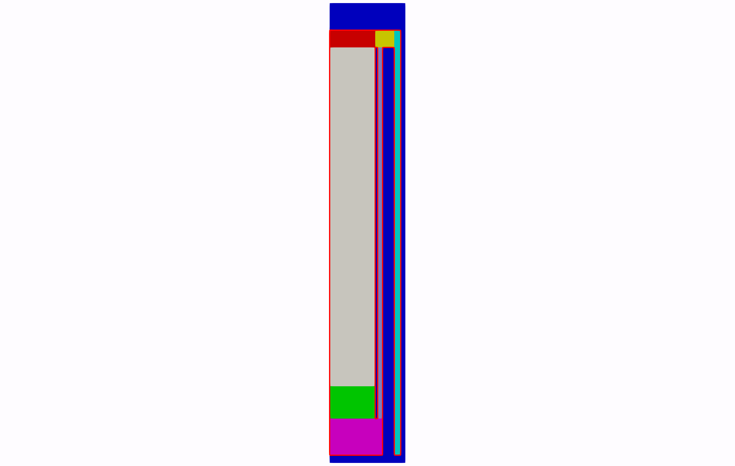
Figure 1: Geometry for Step 7 with the fluid domain framed in red.
Updated Parameters
The thermal_mass_scaling is reduced to obtain faster convergence to steady-state during the pseudo-transient. The hydraulic diameter of the control rods is set to control_rod_Dh = 0.1 because we assume that the control is an empty channel with a diameter of m.
outlet_pressure = 5.84e+6
T_inlet = 533.25
inlet_density = 5.3305
pebble_diameter = 0.06
thermal_mass_scaling = 0.01

mass_flow_rate = 64.3
riser_inner_radius = 1.701
riser_outer_radius = 1.871
flow_area = '${fparse pi * (riser_outer_radius * riser_outer_radius - riser_inner_radius * riser_inner_radius)}'
flow_vel = '${fparse mass_flow_rate / flow_area / inlet_density}'

# scales the heat source to integrate to 200 MW
power_fn_scaling = 0.9792628

# drag coefficient in open flow spaces, set to allow convergence
c_drag_old = 10

# moves the heat source around axially to have the peak in the right spot
offset = -1.45819

# the y-coordinate of the top of the core
top_core = 10.9515

# hydraulic diameters (excluding bed where it's pebble diameter)
bottom_reflector_Dh = 0.1
riser_Dh = 0.17
control_rod_Dh = 0.1Materials
The control rod block has a porosity of . The porosity is computed as the ratio of control rod channel area (number of control rods times area of a circle of diameter m) and the area of the porous flow region perpendicular to the vertical axis that represent the control rod in this model. The porosity is added here:
[FunctorMaterials]
  [porosity_material]
    type = ADPiecewiseByBlockFunctorMaterial
    prop_name = porosity
    subdomain_to_prop_value = 'pebble_bed       0.39
                               cavity           1
                               bottom_reflector 0.3
                               side_reflector   0
                               riser            0.32
                               upper_plenum     0.2
                               bottom_plenum    0.2
                               control_rods     0.32'
  []
[]and the hydraulic diameter is added here:
[FunctorMaterials]
  [characteristic_length]
    type = PiecewiseByBlockFunctorMaterial
    prop_name = characteristic_length
    subdomain_to_prop_value = 'pebble_bed       ${pebble_diameter}
                               bottom_reflector ${bottom_reflector_Dh}
                               riser            ${riser_Dh}
                               control_rods     ${control_rod_Dh}'
  []
[]The solid properties (rho_s, cp_s, kappa_s) are set just like for the other non-pebble-bed regions using a ADGenericFunctorMaterial:
[FunctorMaterials]
  [graphite_rho_and_cp_riser_control_rods]
    type = ADGenericFunctorMaterial
    prop_names = 'rho_s  cp_s kappa_s'
    prop_values = '1780.0 1697 ${fparse 0.68 * 26}'
    block = 'riser control_rods'
  []
[]The drag coefficient in the control_rods is used to adjust the bypass flow to between and % of the nominal mass flow rate. The Darcy coefficient is set to and the Forchheimer coefficient is set by a LinearFrictionFactorFunctorMaterial object.
  [Darcy_control_rods]
    type = ADGenericVectorFunctorMaterial
    prop_names = 'Darcy_coefficient'
    prop_values = '0 0 0'
    block = 'control_rods'
  []

  [quad_drag_new_convention]
    type = ADParsedFunctorMaterial
    # This performs the conversion from the old convention of specifying W for a (W rho u) friction term
    # to the current one of specifying the coefficient for friction computed as: Forchheimer_coef * rho * v / 2
    expression = '1000 * 2 / porosity / speed'
    property_name = new_g
    functor_symbols = 'porosity speed'
    functor_names = 'porosity speed'
  []
  [Forchheimer_control_rods]
    type = LinearFrictionFactorFunctorMaterial
    porosity = porosity
    functor_name = Forchheimer_coefficient
    superficial_vel_x = superficial_vel_x
    superficial_vel_y = superficial_vel_y
    f = 0
    g = new_g
    B = '1 1 1'
    block = 'control_rods'
[]In Forchheimer_control_rods, g=1000 is the Forchheimer coefficient and B can be used to make the Forchheimer coefficient anisotropic. In this case, we just make it isotropic. f must be provided but it corresponds to a linear contribution to the pressure drop which we choose to not use in this example.
Postprocessors
The mass flow rate through the bypass flow channel is measured using this postprocessor:
[Postprocessors]
  [cr_mfr]
    type = VolumetricFlowRate
    advected_quantity = rho
    vel_x = 'superficial_vel_x'
    vel_y = 'superficial_vel_y'
    boundary = 'control_rod_outlet'
    rhie_chow_user_object = pins_rhie_chow_interpolator
    outputs = none
  []
[]Note, the postprocessor is not outputted anywhere because of the outputs = none line. The fraction of mass flow going through the control rod channel is computed by cr_mfr_fraction:
[Postprocessors]
  [cr_mfr_fraction]
    type = ParsedPostprocessor
    pp_names = 'cr_mfr inlet_mfr'
    expression = 'abs(cr_mfr / inlet_mfr * 100)'
  []
[]Executioner
MOOSE allows the user to run a pseudo-transient until it achieves steady-state. This is accomplished by adding:
  steady_state_detection = true
  steady_state_tolerance = 1e-10
steady_state_start_time = 1000to the Executioner block. This switches on steady-state detection starting at t=1000s and stops the simulation once the steady-state relative differential norm has dropped below .
Execution
./pronghorn-opt -i step7.i(htgr/generic-pbr-tutorial/step7.i)
# ==============================================================================
# Model description:
# Step7 - Step6 plus control eod bypass.
# ------------------------------------------------------------------------------
# Idaho Falls, INL, August 15, 2023 04:03 PM
# Author(s): Joseph R. Brennan, Dr. Sebastian Schunert, Dr. Mustafa K. Jaradat
#            and Dr. Paolo Balestra.
# ==============================================================================
outlet_pressure = 5.84e+6
T_inlet = 533.25
inlet_density = 5.3305
pebble_diameter = 0.06
thermal_mass_scaling = 0.01

mass_flow_rate = 64.3
riser_inner_radius = 1.701
riser_outer_radius = 1.871
flow_area = '${fparse pi * (riser_outer_radius * riser_outer_radius - riser_inner_radius * riser_inner_radius)}'
flow_vel = '${fparse mass_flow_rate / flow_area / inlet_density}'

# scales the heat source to integrate to 200 MW
power_fn_scaling = 0.9792628

# drag coefficient in open flow spaces, set to allow convergence
c_drag_old = 10

# moves the heat source around axially to have the peak in the right spot
offset = -1.45819

# the y-coordinate of the top of the core
top_core = 10.9515

# hydraulic diameters (excluding bed where it's pebble diameter)
bottom_reflector_Dh = 0.1
riser_Dh = 0.17
control_rod_Dh = 0.1

[Mesh]
  type = MeshGeneratorMesh
  block_id = '1 2 3 4 5 6 7 8'
  block_name = 'pebble_bed
                cavity
                bottom_reflector
                side_reflector
                upper_plenum
                bottom_plenum
                riser
                control_rods'

  [cartesian_mesh]
    type = CartesianMeshGenerator
    dim = 2

    dx = '0.20 0.20 0.20 0.20 0.20 0.20
          0.010 0.055
          0.13
          0.102 0.102 0.102
          0.17
          0.120'

    ix = '1 1 1 1 1 1
          1 1
          1
          1 1 1
          2
          1'

    dy = '0.100 0.100
          0.967
          0.1709 0.1709 0.1709 0.1709 0.1709
          0.4465 0.4465 0.4465 0.4465 0.4465 0.4465 0.4465 0.4465 0.4465 0.4465
          0.4465 0.4465 0.4465 0.4465 0.4465 0.4465 0.4465 0.4465 0.4465 0.4465
          0.458 0.712'

    iy = '1 2
          2
          2 2 1 1 1
          4 1 1 1 1 1 1 1 1 1
          1 1 1 1 1 1 1 1 1 4
          4 2'

    subdomain_id = '4 4 4 4 4 4 4 4 4 4 4 4 4 4
                    4 4 4 4 4 4 4 4 4 4 4 4 4 4
                    6 6 6 6 6 6 6 6 6 4 4 4 7 4
                    3 3 3 3 3 3 4 4 8 4 4 4 7 4
                    3 3 3 3 3 3 4 4 8 4 4 4 7 4
                    3 3 3 3 3 3 4 4 8 4 4 4 7 4
                    3 3 3 3 3 3 4 4 8 4 4 4 7 4
                    3 3 3 3 3 3 4 4 8 4 4 4 7 4
                    1 1 1 1 1 1 4 4 8 4 4 4 7 4
                    1 1 1 1 1 1 4 4 8 4 4 4 7 4
                    1 1 1 1 1 1 4 4 8 4 4 4 7 4
                    1 1 1 1 1 1 4 4 8 4 4 4 7 4
                    1 1 1 1 1 1 4 4 8 4 4 4 7 4
                    1 1 1 1 1 1 4 4 8 4 4 4 7 4
                    1 1 1 1 1 1 4 4 8 4 4 4 7 4
                    1 1 1 1 1 1 4 4 8 4 4 4 7 4
                    1 1 1 1 1 1 4 4 8 4 4 4 7 4
                    1 1 1 1 1 1 4 4 8 4 4 4 7 4
                    1 1 1 1 1 1 4 4 8 4 4 4 7 4
                    1 1 1 1 1 1 4 4 8 4 4 4 7 4
                    1 1 1 1 1 1 4 4 8 4 4 4 7 4
                    1 1 1 1 1 1 4 4 8 4 4 4 7 4
                    1 1 1 1 1 1 4 4 8 4 4 4 7 4
                    1 1 1 1 1 1 4 4 8 4 4 4 7 4
                    1 1 1 1 1 1 4 4 8 4 4 4 7 4
                    1 1 1 1 1 1 4 4 8 4 4 4 7 4
                    1 1 1 1 1 1 4 4 8 4 4 4 7 4
                    1 1 1 1 1 1 4 4 8 4 4 4 7 4
                    2 2 2 2 2 2 5 5 5 5 5 5 7 4
                    4 4 4 4 4 4 4 4 4 4 4 4 4 4'
  []

  [inlet]
    type = SideSetsAroundSubdomainGenerator
    input = cartesian_mesh
    block = 7
    new_boundary = inlet
    normal = '0 -1 0'
  []

  [riser_top]
    type = SideSetsAroundSubdomainGenerator
    input = inlet
    block = 7
    new_boundary = riser_top
    normal = '0 1 0'
  []

  [riser_right]
    type = SideSetsAroundSubdomainGenerator
    input = riser_top
    block = 7
    new_boundary = riser_right
    normal = '1 0 0'
  []

  [riser_left]
    type = ParsedGenerateSideset
    input = riser_right
    combinatorial_geometry = 'abs(x-1.701) < 1e-3'
    included_subdomains = 7
    included_neighbors = 4
    new_sideset_name = riser_left
  []

  [upper_plenum_top]
    type = SideSetsAroundSubdomainGenerator
    input = riser_left
    block = 5
    new_boundary = upper_plenum_top
    normal = '0 1 0'
  []

  [upper_plenum_bottom]
    type = ParsedGenerateSideset
    input = upper_plenum_top
    combinatorial_geometry = 'abs(y - 11.335) < 1e-3'
    included_subdomains = 5
    included_neighbors = 4
    new_sideset_name = upper_plenum_bottom
  []

  [cavity_top]
    type = SideSetsAroundSubdomainGenerator
    input = upper_plenum_bottom
    block = 2
    new_boundary = cavity_top
    normal = '0 1 0'
  []

  [cavity_left]
    type = SideSetsAroundSubdomainGenerator
    input = cavity_top
    block = 2
    new_boundary = cavity_left
    normal = '-1 0 0'
  []

  [bed_left]
    type = SideSetsAroundSubdomainGenerator
    input = cavity_left
    block = 1
    new_boundary = bed_left
    normal = '-1 0 0'
  []

  [bed_right]
    type = SideSetsAroundSubdomainGenerator
    input = bed_left
    block = 1
    new_boundary = bed_right
    normal = '1 0 0'
  []

  [bottom_reflector_left]
    type = SideSetsAroundSubdomainGenerator
    input = bed_right
    block = 3
    new_boundary = bottom_reflector_left
    normal = '-1 0 0'
  []

  [bottom_reflector_right]
    type = SideSetsAroundSubdomainGenerator
    input = bottom_reflector_left
    block = 3
    new_boundary = bottom_reflector_right
    normal = '1 0 0'
  []

  [bottom_plenum_left]
    type = SideSetsAroundSubdomainGenerator
    input = bottom_reflector_right
    block = 6
    new_boundary = bottom_plenum_left
    normal = '-1 0 0'
  []

  [bottom_plenum_bottom]
    type = SideSetsAroundSubdomainGenerator
    input = bottom_plenum_left
    block = 6
    new_boundary = bottom_plenum_bottom
    normal = '0 -1 0'
  []

  [bottom_plenum_top]
    type = ParsedGenerateSideset
    input = bottom_plenum_bottom
    combinatorial_geometry = 'abs(y-1.167) < 1e-3'
    included_subdomains = 6
    included_neighbors = 4
    new_sideset_name = bottom_plenum_top
  []

  [control_rod_right]
    type = SideSetsAroundSubdomainGenerator
    input = bottom_plenum_top
    block = 8
    new_boundary = control_rod_right
    normal = '1 0 0'
  []

  [control_rod_left]
    type = SideSetsAroundSubdomainGenerator
    input = control_rod_right
    block = 8
    new_boundary = control_rod_left
    normal = '-1 0 0'
  []

  [control_rods_bttom_plenum]
    type = SideSetsBetweenSubdomainsGenerator
    input = control_rod_left
    new_boundary = control_rod_outlet
    primary_block = 8
    paired_block = 6
  []

  [outlet]
    type = SideSetsAroundSubdomainGenerator
    input = control_rods_bttom_plenum
    block = 6
    new_boundary = outlet
    normal = '1 0 0'
  []

  [cr_top]
    type = ParsedGenerateSideset
    combinatorial_geometry = 'abs(y - 10.9515) < 1e-6'
    included_subdomains = '5'
    included_neighbors = '4'
    new_sideset_name = cr_top
    input = outlet
  []

  [rename_boundaries]
    type = RenameBoundaryGenerator
    input = cr_top
    old_boundary = 'cr_top riser_right riser_top upper_plenum_top cavity_top cavity_left bed_left bottom_reflector_left bottom_plenum_left bottom_plenum_bottom riser_left bed_right bottom_reflector_right bottom_plenum_top control_rod_left control_rod_right'
    new_boundary = 'in in in in in ex ex ex ex in in in in in in in'
  []

  [remove_boundaries]
    type = BoundaryDeletionGenerator
    input = rename_boundaries
    boundary_names = 'left right top bottom'
  []

  coord_type = RZ
[]

[FluidProperties]
  [fluid_properties_obj]
    type = HeliumFluidProperties
  []
[]

[Functions]
  [heat_source_fn]
    type = ParsedFunction
    expression = '${power_fn_scaling} * (-1.0612e4 * pow(y+${offset}, 4) + 1.5963e5 * pow(y+${offset}, 3)
                   -6.2993e5 * pow(y+${offset}, 2) + 1.4199e6 * (y+${offset}) + 5.5402e4)'
  []
[]

[Variables]
  [T_solid]
    type = INSFVEnergyVariable
    initial_condition = ${T_inlet}
    block = 'pebble_bed
             bottom_reflector
             side_reflector
             riser
             upper_plenum
             bottom_plenum
             control_rods'
  []
[]

[FVKernels]
  [energy_storage]
    type = PINSFVEnergyTimeDerivative
    variable = T_solid
    rho = rho_s
    cp = cp_s
    is_solid = true
    scaling = ${thermal_mass_scaling}
    porosity = porosity
  []

  [solid_energy_diffusion_core]
    type = FVAnisotropicDiffusion
    variable = T_solid
    coeff = 'effective_thermal_conductivity'
  []

  [heating]
    type = FVBodyForce
    variable = T_solid
    function = heat_source_fn
    block = 'pebble_bed'
  []

  [convection_pebble_bed_fluid]
    type = PINSFVEnergyAmbientConvection
    variable = T_solid
    T_fluid = T_fluid
    T_solid = T_solid
    is_solid = true
    h_solid_fluid = 'alpha'
    block = 'pebble_bed bottom_reflector'
  []
[]

[Modules]
  [NavierStokesFV]
    # external variable definition

    # general control parameters
    compressibility = 'weakly-compressible'
    porous_medium_treatment = true
    add_energy_equation = true
    block = 'pebble_bed cavity bottom_reflector upper_plenum bottom_plenum riser control_rods'

    # material property parameters
    density = rho
    dynamic_viscosity = mu
    thermal_conductivity = kappa

    # porous medium treatment parameters
    porosity = porosity
    porosity_interface_pressure_treatment = 'bernoulli'

    # initial conditions
    initial_velocity = '1e-6 1e-6 0'
    initial_pressure = ${outlet_pressure}
    initial_temperature = ${T_inlet}

    # inlet boundary conditions
    inlet_boundaries = inlet
    momentum_inlet_types = fixed-velocity
    momentum_inlet_function = '0 ${flow_vel}'
    energy_inlet_types = fixed-temperature
    energy_inlet_function = '${T_inlet}'

    # wall boundary conditions
    wall_boundaries = 'ex in'
    momentum_wall_types = 'slip slip'
    energy_wall_types = 'heatflux heatflux'
    energy_wall_function = '0 0'

    # outlet boundary conditions
    outlet_boundaries = outlet
    momentum_outlet_types = fixed-pressure
    pressure_function = ${outlet_pressure}

    # friction control parameters
    friction_types = 'darcy forchheimer'
    friction_coeffs = 'Darcy_coefficient Forchheimer_coefficient'

    # energy equation parameters
    ambient_convection_blocks = 'pebble_bed bottom_reflector'
    ambient_convection_alpha = 'alpha'
    ambient_temperature = 'T_solid'
  []
[]

[UserObjects]
  [bed_geometry]
    type = WallDistanceCylindricalBed
    top = ${top_core}
    inner_radius = 0.0
    outer_radius = 1.2
  []
[]

[FunctorMaterials]
  [fluid_props_to_mat_props]
    type = GeneralFunctorFluidProps
    fp = fluid_properties_obj
    porosity = porosity
    pressure = pressure
    T_fluid = T_fluid
    speed = speed
    characteristic_length = characteristic_length
    block = 'pebble_bed cavity bottom_reflector upper_plenum bottom_plenum riser control_rods'
    neglect_derivatives_of_density_time_derivative = false
  []

  [graphite_rho_and_cp_bed]
    type = ADGenericFunctorMaterial
    prop_names = 'rho_s  cp_s k_s'
    prop_values = '1780.0 1697 26'
    block = 'pebble_bed'
  []

  [graphite_rho_and_cp_side_reflector]
    type = ADGenericFunctorMaterial
    prop_names = 'rho_s  cp_s kappa_s'
    prop_values = '1780.0 1697 ${fparse 1 * 26}'
    block = 'side_reflector'
  []

  [graphite_rho_and_cp_bottom_reflector]
    type = ADGenericFunctorMaterial
    prop_names = 'rho_s  cp_s kappa_s'
    prop_values = '1780.0 1697 ${fparse 0.7 * 26}'
    block = 'bottom_reflector'
  []

  [graphite_rho_and_cp_riser_control_rods]
    type = ADGenericFunctorMaterial
    prop_names = 'rho_s  cp_s kappa_s'
    prop_values = '1780.0 1697 ${fparse 0.68 * 26}'
    block = 'riser control_rods'
  []

  [graphite_rho_and_cp_plenums]
    type = ADGenericFunctorMaterial
    prop_names = 'rho_s  cp_s kappa_s'
    prop_values = '1780.0 1697 ${fparse 0.8 * 26}'
    block = 'upper_plenum bottom_plenum'
  []

  [drag_pebble_bed]
    type = FunctorKTADragCoefficients
    fp = fluid_properties_obj
    pebble_diameter = ${pebble_diameter}
    porosity = porosity
    T_fluid = T_fluid
    T_solid = T_solid
    block = pebble_bed
  []

  [drag_new_convention]
    type = ADParsedFunctorMaterial
    # This performs the conversion from the old convention of specifying W for a (W rho u) friction term
    # to the current one of specifying the coefficient for friction computed as: Darcy_coef * mu * u / eps
    expression = '${c_drag_old} * rho_fluid / porosity / fluid_mu'
    property_name = c_drag
    functor_symbols = 'rho_fluid porosity fluid_mu'
    functor_names = 'rho porosity mu'
  []

  [drag_cavity]
    type = ADGenericVectorFunctorMaterial
    prop_names = 'Darcy_coefficient Forchheimer_coefficient'
    prop_values = 'c_drag c_drag c_drag 0 0 0'
    block = 'cavity'
  []

  [drag_upper_plenum]
    type = ADGenericVectorFunctorMaterial
    prop_names = 'Darcy_coefficient Forchheimer_coefficient'
    prop_values = 'c_drag c_drag c_drag 0 0 0'
    block = 'upper_plenum'
  []

  [drag_bottom_plenum]
    type = ADGenericVectorFunctorMaterial
    prop_names = 'Darcy_coefficient Forchheimer_coefficient'
    prop_values = 'c_drag c_drag c_drag 0 0 0'
    block = 'bottom_plenum'
  []

  [drag_bottom_reflector_riser]
    type = FunctorChurchillDragCoefficients
    block = 'bottom_reflector riser'
    multipliers = '1e4 1 1e4'
  []

  [Darcy_control_rods]
    type = ADGenericVectorFunctorMaterial
    prop_names = 'Darcy_coefficient'
    prop_values = '0 0 0'
    block = 'control_rods'
  []

  [quad_drag_new_convention]
    type = ADParsedFunctorMaterial
    # This performs the conversion from the old convention of specifying W for a (W rho u) friction term
    # to the current one of specifying the coefficient for friction computed as: Forchheimer_coef * rho * v / 2
    expression = '1000 * 2 / porosity / speed'
    property_name = new_g
    functor_symbols = 'porosity speed'
    functor_names = 'porosity speed'
  []
  [Forchheimer_control_rods]
    type = LinearFrictionFactorFunctorMaterial
    porosity = porosity
    functor_name = Forchheimer_coefficient
    superficial_vel_x = superficial_vel_x
    superficial_vel_y = superficial_vel_y
    f = 0
    g = new_g
    B = '1 1 1'
    block = 'control_rods'
  []

  [porosity_material]
    type = ADPiecewiseByBlockFunctorMaterial
    prop_name = porosity
    subdomain_to_prop_value = 'pebble_bed       0.39
                               cavity           1
                               bottom_reflector 0.3
                               side_reflector   0
                               riser            0.32
                               upper_plenum     0.2
                               bottom_plenum    0.2
                               control_rods     0.32'
  []

  [kappa_s_pebble_bed]
    type = FunctorPebbleBedKappaSolid
    T_solid = T_solid
    porosity = porosity
    solid_conduction = ZBS
    emissivity = 0.8
    infinite_porosity = 0.39
    Youngs_modulus = 9e+9
    Poisson_ratio = 0.1360
    lattice_parameters = interpolation
    coordination_number = You
    wall_distance = bed_geometry
    block = 'pebble_bed'
    pebble_diameter = ${pebble_diameter}
    acceleration = '0.00 -9.81 0.00 '
  []

  [effective_pebble_bed_thermal_conductivity]
    type = ADGenericVectorFunctorMaterial
    prop_names = 'effective_thermal_conductivity'
    prop_values = 'kappa_s kappa_s kappa_s'
    block = 'pebble_bed
             bottom_reflector
             side_reflector
             riser
             upper_plenum
             bottom_plenum
             control_rods'
  []

  [kappa_f_pebble_bed]
    type = FunctorLinearPecletKappaFluid
    porosity = porosity
    block = 'pebble_bed'
  []

  [kappa_f_mat_no_pebble_bed]
    type = ADGenericVectorFunctorMaterial
    prop_names = 'kappa'
    prop_values = 'k k k'
    block = 'cavity bottom_reflector upper_plenum bottom_plenum riser control_rods'
  []

  [pebble_bed_alpha]
    type = FunctorKTAPebbleBedHTC
    T_solid = T_solid
    T_fluid = T_fluid
    mu = mu
    porosity = porosity
    pressure = pressure
    fp = fluid_properties_obj
    pebble_diameter = ${pebble_diameter}
    block = 'pebble_bed'
  []

  [reflector_alpha]
    type = ADGenericFunctorMaterial
    prop_names = 'alpha'
    prop_values = '2e4'
    block = 'bottom_reflector'
  []

  [characteristic_length]
    type = PiecewiseByBlockFunctorMaterial
    prop_name = characteristic_length
    subdomain_to_prop_value = 'pebble_bed       ${pebble_diameter}
                               bottom_reflector ${bottom_reflector_Dh}
                               riser            ${riser_Dh}
                               control_rods     ${control_rod_Dh}'
  []
[]

[Executioner]
  type = Transient
  [TimeStepper]
    type = IterationAdaptiveDT
    iteration_window = 2
    optimal_iterations = 8
    cutback_factor = 0.8
    growth_factor = 1.2
    dt = 0.01
  []
  line_search = l2
  solve_type = 'NEWTON'
  petsc_options_iname = '-pc_type -pc_factor_shift_type -pc_factor_mat_solver_package'
  petsc_options_value = 'lu NONZERO superlu_dist'
  nl_rel_tol = 1e-6
  nl_abs_tol = 1e-5
  nl_max_its = 20
  automatic_scaling = true
  steady_state_detection = true
  steady_state_tolerance = 1e-10
  steady_state_start_time = 1000
[]

[Postprocessors]
  [inlet_mfr]
    type = VolumetricFlowRate
    advected_quantity = rho
    vel_x = 'superficial_vel_x'
    vel_y = 'superficial_vel_y'
    boundary = 'inlet'
    rhie_chow_user_object = pins_rhie_chow_interpolator
  []

  [outlet_mfr]
    type = VolumetricFlowRate
    advected_quantity = rho
    vel_x = 'superficial_vel_x'
    vel_y = 'superficial_vel_y'
    boundary = 'outlet'
    rhie_chow_user_object = pins_rhie_chow_interpolator
  []

  [cr_mfr]
    type = VolumetricFlowRate
    advected_quantity = rho
    vel_x = 'superficial_vel_x'
    vel_y = 'superficial_vel_y'
    boundary = 'control_rod_outlet'
    rhie_chow_user_object = pins_rhie_chow_interpolator
    outputs = none
  []

  [cr_mfr_fraction]
    type = ParsedPostprocessor
    pp_names = 'cr_mfr inlet_mfr'
    expression = 'abs(cr_mfr / inlet_mfr * 100)'
  []

  [inlet_pressure]
    type = SideAverageValue
    variable = pressure
    boundary = inlet
    outputs = none
  []

  [outlet_pressure]
    type = SideAverageValue
    variable = pressure
    boundary = outlet
    outputs = none
  []

  [pressure_drop]
    type = ParsedPostprocessor
    pp_names = 'inlet_pressure outlet_pressure'
    expression = 'inlet_pressure - outlet_pressure'
  []

  [enthalpy_inlet]
    type = VolumetricFlowRate
    boundary = inlet
    vel_x = superficial_vel_x
    vel_y = superficial_vel_y
    rhie_chow_user_object = 'pins_rhie_chow_interpolator'
    advected_quantity = 'rho_cp_temp'
    advected_interp_method = 'upwind'
    outputs = none
  []

  [enthalpy_outlet]
    type = VolumetricFlowRate
    boundary = outlet
    vel_x = superficial_vel_x
    vel_y = superficial_vel_y
    rhie_chow_user_object = 'pins_rhie_chow_interpolator'
    advected_quantity = 'rho_cp_temp'
    advected_interp_method = 'upwind'
    outputs = none
  []

  [enthalpy_balance]
    type = ParsedPostprocessor
    pp_names = 'enthalpy_inlet enthalpy_outlet'
    expression = 'abs(enthalpy_outlet) - abs(enthalpy_inlet)'
  []

  [heat_source_integral]
    type = ElementIntegralFunctorPostprocessor
    functor = heat_source_fn
    block = pebble_bed
  []

  [mass_flux_weighted_Tf_out]
    type = MassFluxWeightedFlowRate
    vel_x = superficial_vel_x
    vel_y = superficial_vel_y
    density = rho
    rhie_chow_user_object = 'pins_rhie_chow_interpolator'
    boundary = outlet
    advected_quantity = T_fluid
  []
[]

[Outputs]
  exodus = true
[]
(htgr/generic-pbr-tutorial/step7.i)
# ==============================================================================
# Model description:
# Step7 - Step6 plus control eod bypass.
# ------------------------------------------------------------------------------
# Idaho Falls, INL, August 15, 2023 04:03 PM
# Author(s): Joseph R. Brennan, Dr. Sebastian Schunert, Dr. Mustafa K. Jaradat
#            and Dr. Paolo Balestra.
# ==============================================================================
outlet_pressure = 5.84e+6
T_inlet = 533.25
inlet_density = 5.3305
pebble_diameter = 0.06
thermal_mass_scaling = 0.01

mass_flow_rate = 64.3
riser_inner_radius = 1.701
riser_outer_radius = 1.871
flow_area = '${fparse pi * (riser_outer_radius * riser_outer_radius - riser_inner_radius * riser_inner_radius)}'
flow_vel = '${fparse mass_flow_rate / flow_area / inlet_density}'

# scales the heat source to integrate to 200 MW
power_fn_scaling = 0.9792628

# drag coefficient in open flow spaces, set to allow convergence
c_drag_old = 10

# moves the heat source around axially to have the peak in the right spot
offset = -1.45819

# the y-coordinate of the top of the core
top_core = 10.9515

# hydraulic diameters (excluding bed where it's pebble diameter)
bottom_reflector_Dh = 0.1
riser_Dh = 0.17
control_rod_Dh = 0.1

[Mesh]
  type = MeshGeneratorMesh
  block_id = '1 2 3 4 5 6 7 8'
  block_name = 'pebble_bed
                cavity
                bottom_reflector
                side_reflector
                upper_plenum
                bottom_plenum
                riser
                control_rods'

  [cartesian_mesh]
    type = CartesianMeshGenerator
    dim = 2

    dx = '0.20 0.20 0.20 0.20 0.20 0.20
          0.010 0.055
          0.13
          0.102 0.102 0.102
          0.17
          0.120'

    ix = '1 1 1 1 1 1
          1 1
          1
          1 1 1
          2
          1'

    dy = '0.100 0.100
          0.967
          0.1709 0.1709 0.1709 0.1709 0.1709
          0.4465 0.4465 0.4465 0.4465 0.4465 0.4465 0.4465 0.4465 0.4465 0.4465
          0.4465 0.4465 0.4465 0.4465 0.4465 0.4465 0.4465 0.4465 0.4465 0.4465
          0.458 0.712'

    iy = '1 2
          2
          2 2 1 1 1
          4 1 1 1 1 1 1 1 1 1
          1 1 1 1 1 1 1 1 1 4
          4 2'

    subdomain_id = '4 4 4 4 4 4 4 4 4 4 4 4 4 4
                    4 4 4 4 4 4 4 4 4 4 4 4 4 4
                    6 6 6 6 6 6 6 6 6 4 4 4 7 4
                    3 3 3 3 3 3 4 4 8 4 4 4 7 4
                    3 3 3 3 3 3 4 4 8 4 4 4 7 4
                    3 3 3 3 3 3 4 4 8 4 4 4 7 4
                    3 3 3 3 3 3 4 4 8 4 4 4 7 4
                    3 3 3 3 3 3 4 4 8 4 4 4 7 4
                    1 1 1 1 1 1 4 4 8 4 4 4 7 4
                    1 1 1 1 1 1 4 4 8 4 4 4 7 4
                    1 1 1 1 1 1 4 4 8 4 4 4 7 4
                    1 1 1 1 1 1 4 4 8 4 4 4 7 4
                    1 1 1 1 1 1 4 4 8 4 4 4 7 4
                    1 1 1 1 1 1 4 4 8 4 4 4 7 4
                    1 1 1 1 1 1 4 4 8 4 4 4 7 4
                    1 1 1 1 1 1 4 4 8 4 4 4 7 4
                    1 1 1 1 1 1 4 4 8 4 4 4 7 4
                    1 1 1 1 1 1 4 4 8 4 4 4 7 4
                    1 1 1 1 1 1 4 4 8 4 4 4 7 4
                    1 1 1 1 1 1 4 4 8 4 4 4 7 4
                    1 1 1 1 1 1 4 4 8 4 4 4 7 4
                    1 1 1 1 1 1 4 4 8 4 4 4 7 4
                    1 1 1 1 1 1 4 4 8 4 4 4 7 4
                    1 1 1 1 1 1 4 4 8 4 4 4 7 4
                    1 1 1 1 1 1 4 4 8 4 4 4 7 4
                    1 1 1 1 1 1 4 4 8 4 4 4 7 4
                    1 1 1 1 1 1 4 4 8 4 4 4 7 4
                    1 1 1 1 1 1 4 4 8 4 4 4 7 4
                    2 2 2 2 2 2 5 5 5 5 5 5 7 4
                    4 4 4 4 4 4 4 4 4 4 4 4 4 4'
  []

  [inlet]
    type = SideSetsAroundSubdomainGenerator
    input = cartesian_mesh
    block = 7
    new_boundary = inlet
    normal = '0 -1 0'
  []

  [riser_top]
    type = SideSetsAroundSubdomainGenerator
    input = inlet
    block = 7
    new_boundary = riser_top
    normal = '0 1 0'
  []

  [riser_right]
    type = SideSetsAroundSubdomainGenerator
    input = riser_top
    block = 7
    new_boundary = riser_right
    normal = '1 0 0'
  []

  [riser_left]
    type = ParsedGenerateSideset
    input = riser_right
    combinatorial_geometry = 'abs(x-1.701) < 1e-3'
    included_subdomains = 7
    included_neighbors = 4
    new_sideset_name = riser_left
  []

  [upper_plenum_top]
    type = SideSetsAroundSubdomainGenerator
    input = riser_left
    block = 5
    new_boundary = upper_plenum_top
    normal = '0 1 0'
  []

  [upper_plenum_bottom]
    type = ParsedGenerateSideset
    input = upper_plenum_top
    combinatorial_geometry = 'abs(y - 11.335) < 1e-3'
    included_subdomains = 5
    included_neighbors = 4
    new_sideset_name = upper_plenum_bottom
  []

  [cavity_top]
    type = SideSetsAroundSubdomainGenerator
    input = upper_plenum_bottom
    block = 2
    new_boundary = cavity_top
    normal = '0 1 0'
  []

  [cavity_left]
    type = SideSetsAroundSubdomainGenerator
    input = cavity_top
    block = 2
    new_boundary = cavity_left
    normal = '-1 0 0'
  []

  [bed_left]
    type = SideSetsAroundSubdomainGenerator
    input = cavity_left
    block = 1
    new_boundary = bed_left
    normal = '-1 0 0'
  []

  [bed_right]
    type = SideSetsAroundSubdomainGenerator
    input = bed_left
    block = 1
    new_boundary = bed_right
    normal = '1 0 0'
  []

  [bottom_reflector_left]
    type = SideSetsAroundSubdomainGenerator
    input = bed_right
    block = 3
    new_boundary = bottom_reflector_left
    normal = '-1 0 0'
  []

  [bottom_reflector_right]
    type = SideSetsAroundSubdomainGenerator
    input = bottom_reflector_left
    block = 3
    new_boundary = bottom_reflector_right
    normal = '1 0 0'
  []

  [bottom_plenum_left]
    type = SideSetsAroundSubdomainGenerator
    input = bottom_reflector_right
    block = 6
    new_boundary = bottom_plenum_left
    normal = '-1 0 0'
  []

  [bottom_plenum_bottom]
    type = SideSetsAroundSubdomainGenerator
    input = bottom_plenum_left
    block = 6
    new_boundary = bottom_plenum_bottom
    normal = '0 -1 0'
  []

  [bottom_plenum_top]
    type = ParsedGenerateSideset
    input = bottom_plenum_bottom
    combinatorial_geometry = 'abs(y-1.167) < 1e-3'
    included_subdomains = 6
    included_neighbors = 4
    new_sideset_name = bottom_plenum_top
  []

  [control_rod_right]
    type = SideSetsAroundSubdomainGenerator
    input = bottom_plenum_top
    block = 8
    new_boundary = control_rod_right
    normal = '1 0 0'
  []

  [control_rod_left]
    type = SideSetsAroundSubdomainGenerator
    input = control_rod_right
    block = 8
    new_boundary = control_rod_left
    normal = '-1 0 0'
  []

  [control_rods_bttom_plenum]
    type = SideSetsBetweenSubdomainsGenerator
    input = control_rod_left
    new_boundary = control_rod_outlet
    primary_block = 8
    paired_block = 6
  []

  [outlet]
    type = SideSetsAroundSubdomainGenerator
    input = control_rods_bttom_plenum
    block = 6
    new_boundary = outlet
    normal = '1 0 0'
  []

  [cr_top]
    type = ParsedGenerateSideset
    combinatorial_geometry = 'abs(y - 10.9515) < 1e-6'
    included_subdomains = '5'
    included_neighbors = '4'
    new_sideset_name = cr_top
    input = outlet
  []

  [rename_boundaries]
    type = RenameBoundaryGenerator
    input = cr_top
    old_boundary = 'cr_top riser_right riser_top upper_plenum_top cavity_top cavity_left bed_left bottom_reflector_left bottom_plenum_left bottom_plenum_bottom riser_left bed_right bottom_reflector_right bottom_plenum_top control_rod_left control_rod_right'
    new_boundary = 'in in in in in ex ex ex ex in in in in in in in'
  []

  [remove_boundaries]
    type = BoundaryDeletionGenerator
    input = rename_boundaries
    boundary_names = 'left right top bottom'
  []

  coord_type = RZ
[]

[FluidProperties]
  [fluid_properties_obj]
    type = HeliumFluidProperties
  []
[]

[Functions]
  [heat_source_fn]
    type = ParsedFunction
    expression = '${power_fn_scaling} * (-1.0612e4 * pow(y+${offset}, 4) + 1.5963e5 * pow(y+${offset}, 3)
                   -6.2993e5 * pow(y+${offset}, 2) + 1.4199e6 * (y+${offset}) + 5.5402e4)'
  []
[]

[Variables]
  [T_solid]
    type = INSFVEnergyVariable
    initial_condition = ${T_inlet}
    block = 'pebble_bed
             bottom_reflector
             side_reflector
             riser
             upper_plenum
             bottom_plenum
             control_rods'
  []
[]

[FVKernels]
  [energy_storage]
    type = PINSFVEnergyTimeDerivative
    variable = T_solid
    rho = rho_s
    cp = cp_s
    is_solid = true
    scaling = ${thermal_mass_scaling}
    porosity = porosity
  []

  [solid_energy_diffusion_core]
    type = FVAnisotropicDiffusion
    variable = T_solid
    coeff = 'effective_thermal_conductivity'
  []

  [heating]
    type = FVBodyForce
    variable = T_solid
    function = heat_source_fn
    block = 'pebble_bed'
  []

  [convection_pebble_bed_fluid]
    type = PINSFVEnergyAmbientConvection
    variable = T_solid
    T_fluid = T_fluid
    T_solid = T_solid
    is_solid = true
    h_solid_fluid = 'alpha'
    block = 'pebble_bed bottom_reflector'
  []
[]

[Modules]
  [NavierStokesFV]
    # external variable definition

    # general control parameters
    compressibility = 'weakly-compressible'
    porous_medium_treatment = true
    add_energy_equation = true
    block = 'pebble_bed cavity bottom_reflector upper_plenum bottom_plenum riser control_rods'

    # material property parameters
    density = rho
    dynamic_viscosity = mu
    thermal_conductivity = kappa

    # porous medium treatment parameters
    porosity = porosity
    porosity_interface_pressure_treatment = 'bernoulli'

    # initial conditions
    initial_velocity = '1e-6 1e-6 0'
    initial_pressure = ${outlet_pressure}
    initial_temperature = ${T_inlet}

    # inlet boundary conditions
    inlet_boundaries = inlet
    momentum_inlet_types = fixed-velocity
    momentum_inlet_function = '0 ${flow_vel}'
    energy_inlet_types = fixed-temperature
    energy_inlet_function = '${T_inlet}'

    # wall boundary conditions
    wall_boundaries = 'ex in'
    momentum_wall_types = 'slip slip'
    energy_wall_types = 'heatflux heatflux'
    energy_wall_function = '0 0'

    # outlet boundary conditions
    outlet_boundaries = outlet
    momentum_outlet_types = fixed-pressure
    pressure_function = ${outlet_pressure}

    # friction control parameters
    friction_types = 'darcy forchheimer'
    friction_coeffs = 'Darcy_coefficient Forchheimer_coefficient'

    # energy equation parameters
    ambient_convection_blocks = 'pebble_bed bottom_reflector'
    ambient_convection_alpha = 'alpha'
    ambient_temperature = 'T_solid'
  []
[]

[UserObjects]
  [bed_geometry]
    type = WallDistanceCylindricalBed
    top = ${top_core}
    inner_radius = 0.0
    outer_radius = 1.2
  []
[]

[FunctorMaterials]
  [fluid_props_to_mat_props]
    type = GeneralFunctorFluidProps
    fp = fluid_properties_obj
    porosity = porosity
    pressure = pressure
    T_fluid = T_fluid
    speed = speed
    characteristic_length = characteristic_length
    block = 'pebble_bed cavity bottom_reflector upper_plenum bottom_plenum riser control_rods'
    neglect_derivatives_of_density_time_derivative = false
  []

  [graphite_rho_and_cp_bed]
    type = ADGenericFunctorMaterial
    prop_names = 'rho_s  cp_s k_s'
    prop_values = '1780.0 1697 26'
    block = 'pebble_bed'
  []

  [graphite_rho_and_cp_side_reflector]
    type = ADGenericFunctorMaterial
    prop_names = 'rho_s  cp_s kappa_s'
    prop_values = '1780.0 1697 ${fparse 1 * 26}'
    block = 'side_reflector'
  []

  [graphite_rho_and_cp_bottom_reflector]
    type = ADGenericFunctorMaterial
    prop_names = 'rho_s  cp_s kappa_s'
    prop_values = '1780.0 1697 ${fparse 0.7 * 26}'
    block = 'bottom_reflector'
  []

  [graphite_rho_and_cp_riser_control_rods]
    type = ADGenericFunctorMaterial
    prop_names = 'rho_s  cp_s kappa_s'
    prop_values = '1780.0 1697 ${fparse 0.68 * 26}'
    block = 'riser control_rods'
  []

  [graphite_rho_and_cp_plenums]
    type = ADGenericFunctorMaterial
    prop_names = 'rho_s  cp_s kappa_s'
    prop_values = '1780.0 1697 ${fparse 0.8 * 26}'
    block = 'upper_plenum bottom_plenum'
  []

  [drag_pebble_bed]
    type = FunctorKTADragCoefficients
    fp = fluid_properties_obj
    pebble_diameter = ${pebble_diameter}
    porosity = porosity
    T_fluid = T_fluid
    T_solid = T_solid
    block = pebble_bed
  []

  [drag_new_convention]
    type = ADParsedFunctorMaterial
    # This performs the conversion from the old convention of specifying W for a (W rho u) friction term
    # to the current one of specifying the coefficient for friction computed as: Darcy_coef * mu * u / eps
    expression = '${c_drag_old} * rho_fluid / porosity / fluid_mu'
    property_name = c_drag
    functor_symbols = 'rho_fluid porosity fluid_mu'
    functor_names = 'rho porosity mu'
  []

  [drag_cavity]
    type = ADGenericVectorFunctorMaterial
    prop_names = 'Darcy_coefficient Forchheimer_coefficient'
    prop_values = 'c_drag c_drag c_drag 0 0 0'
    block = 'cavity'
  []

  [drag_upper_plenum]
    type = ADGenericVectorFunctorMaterial
    prop_names = 'Darcy_coefficient Forchheimer_coefficient'
    prop_values = 'c_drag c_drag c_drag 0 0 0'
    block = 'upper_plenum'
  []

  [drag_bottom_plenum]
    type = ADGenericVectorFunctorMaterial
    prop_names = 'Darcy_coefficient Forchheimer_coefficient'
    prop_values = 'c_drag c_drag c_drag 0 0 0'
    block = 'bottom_plenum'
  []

  [drag_bottom_reflector_riser]
    type = FunctorChurchillDragCoefficients
    block = 'bottom_reflector riser'
    multipliers = '1e4 1 1e4'
  []

  [Darcy_control_rods]
    type = ADGenericVectorFunctorMaterial
    prop_names = 'Darcy_coefficient'
    prop_values = '0 0 0'
    block = 'control_rods'
  []

  [quad_drag_new_convention]
    type = ADParsedFunctorMaterial
    # This performs the conversion from the old convention of specifying W for a (W rho u) friction term
    # to the current one of specifying the coefficient for friction computed as: Forchheimer_coef * rho * v / 2
    expression = '1000 * 2 / porosity / speed'
    property_name = new_g
    functor_symbols = 'porosity speed'
    functor_names = 'porosity speed'
  []
  [Forchheimer_control_rods]
    type = LinearFrictionFactorFunctorMaterial
    porosity = porosity
    functor_name = Forchheimer_coefficient
    superficial_vel_x = superficial_vel_x
    superficial_vel_y = superficial_vel_y
    f = 0
    g = new_g
    B = '1 1 1'
    block = 'control_rods'
  []

  [porosity_material]
    type = ADPiecewiseByBlockFunctorMaterial
    prop_name = porosity
    subdomain_to_prop_value = 'pebble_bed       0.39
                               cavity           1
                               bottom_reflector 0.3
                               side_reflector   0
                               riser            0.32
                               upper_plenum     0.2
                               bottom_plenum    0.2
                               control_rods     0.32'
  []

  [kappa_s_pebble_bed]
    type = FunctorPebbleBedKappaSolid
    T_solid = T_solid
    porosity = porosity
    solid_conduction = ZBS
    emissivity = 0.8
    infinite_porosity = 0.39
    Youngs_modulus = 9e+9
    Poisson_ratio = 0.1360
    lattice_parameters = interpolation
    coordination_number = You
    wall_distance = bed_geometry
    block = 'pebble_bed'
    pebble_diameter = ${pebble_diameter}
    acceleration = '0.00 -9.81 0.00 '
  []

  [effective_pebble_bed_thermal_conductivity]
    type = ADGenericVectorFunctorMaterial
    prop_names = 'effective_thermal_conductivity'
    prop_values = 'kappa_s kappa_s kappa_s'
    block = 'pebble_bed
             bottom_reflector
             side_reflector
             riser
             upper_plenum
             bottom_plenum
             control_rods'
  []

  [kappa_f_pebble_bed]
    type = FunctorLinearPecletKappaFluid
    porosity = porosity
    block = 'pebble_bed'
  []

  [kappa_f_mat_no_pebble_bed]
    type = ADGenericVectorFunctorMaterial
    prop_names = 'kappa'
    prop_values = 'k k k'
    block = 'cavity bottom_reflector upper_plenum bottom_plenum riser control_rods'
  []

  [pebble_bed_alpha]
    type = FunctorKTAPebbleBedHTC
    T_solid = T_solid
    T_fluid = T_fluid
    mu = mu
    porosity = porosity
    pressure = pressure
    fp = fluid_properties_obj
    pebble_diameter = ${pebble_diameter}
    block = 'pebble_bed'
  []

  [reflector_alpha]
    type = ADGenericFunctorMaterial
    prop_names = 'alpha'
    prop_values = '2e4'
    block = 'bottom_reflector'
  []

  [characteristic_length]
    type = PiecewiseByBlockFunctorMaterial
    prop_name = characteristic_length
    subdomain_to_prop_value = 'pebble_bed       ${pebble_diameter}
                               bottom_reflector ${bottom_reflector_Dh}
                               riser            ${riser_Dh}
                               control_rods     ${control_rod_Dh}'
  []
[]

[Executioner]
  type = Transient
  [TimeStepper]
    type = IterationAdaptiveDT
    iteration_window = 2
    optimal_iterations = 8
    cutback_factor = 0.8
    growth_factor = 1.2
    dt = 0.01
  []
  line_search = l2
  solve_type = 'NEWTON'
  petsc_options_iname = '-pc_type -pc_factor_shift_type -pc_factor_mat_solver_package'
  petsc_options_value = 'lu NONZERO superlu_dist'
  nl_rel_tol = 1e-6
  nl_abs_tol = 1e-5
  nl_max_its = 20
  automatic_scaling = true
  steady_state_detection = true
  steady_state_tolerance = 1e-10
  steady_state_start_time = 1000
[]

[Postprocessors]
  [inlet_mfr]
    type = VolumetricFlowRate
    advected_quantity = rho
    vel_x = 'superficial_vel_x'
    vel_y = 'superficial_vel_y'
    boundary = 'inlet'
    rhie_chow_user_object = pins_rhie_chow_interpolator
  []

  [outlet_mfr]
    type = VolumetricFlowRate
    advected_quantity = rho
    vel_x = 'superficial_vel_x'
    vel_y = 'superficial_vel_y'
    boundary = 'outlet'
    rhie_chow_user_object = pins_rhie_chow_interpolator
  []

  [cr_mfr]
    type = VolumetricFlowRate
    advected_quantity = rho
    vel_x = 'superficial_vel_x'
    vel_y = 'superficial_vel_y'
    boundary = 'control_rod_outlet'
    rhie_chow_user_object = pins_rhie_chow_interpolator
    outputs = none
  []

  [cr_mfr_fraction]
    type = ParsedPostprocessor
    pp_names = 'cr_mfr inlet_mfr'
    expression = 'abs(cr_mfr / inlet_mfr * 100)'
  []

  [inlet_pressure]
    type = SideAverageValue
    variable = pressure
    boundary = inlet
    outputs = none
  []

  [outlet_pressure]
    type = SideAverageValue
    variable = pressure
    boundary = outlet
    outputs = none
  []

  [pressure_drop]
    type = ParsedPostprocessor
    pp_names = 'inlet_pressure outlet_pressure'
    expression = 'inlet_pressure - outlet_pressure'
  []

  [enthalpy_inlet]
    type = VolumetricFlowRate
    boundary = inlet
    vel_x = superficial_vel_x
    vel_y = superficial_vel_y
    rhie_chow_user_object = 'pins_rhie_chow_interpolator'
    advected_quantity = 'rho_cp_temp'
    advected_interp_method = 'upwind'
    outputs = none
  []

  [enthalpy_outlet]
    type = VolumetricFlowRate
    boundary = outlet
    vel_x = superficial_vel_x
    vel_y = superficial_vel_y
    rhie_chow_user_object = 'pins_rhie_chow_interpolator'
    advected_quantity = 'rho_cp_temp'
    advected_interp_method = 'upwind'
    outputs = none
  []

  [enthalpy_balance]
    type = ParsedPostprocessor
    pp_names = 'enthalpy_inlet enthalpy_outlet'
    expression = 'abs(enthalpy_outlet) - abs(enthalpy_inlet)'
  []

  [heat_source_integral]
    type = ElementIntegralFunctorPostprocessor
    functor = heat_source_fn
    block = pebble_bed
  []

  [mass_flux_weighted_Tf_out]
    type = MassFluxWeightedFlowRate
    vel_x = superficial_vel_x
    vel_y = superficial_vel_y
    density = rho
    rhie_chow_user_object = 'pins_rhie_chow_interpolator'
    boundary = outlet
    advected_quantity = T_fluid
  []
[]

[Outputs]
  exodus = true
[]