Modular High-Temperature Gas-Cooled Reactor (3D-MHTGR) Mesh
This meshing script is provided as is in a coarse form. Convergence studies for the physics of interest should be performed by the user.
The hexagonal core mesh is created in several steps:
Meshes are generated for burnable poison pins and fuel pin geometry.
The large coolant and small coolant channel geometries are modeled.
Empty pins are modeled to represent the reflector only hexagonal unit cell, which will be deleted from the overall mesh to create the reserve shut-down control (RSC) channel.
The mesh is assembled by combining all of the individual meshes previously generated.
A more detailed explanation of each step follows below.
Throughout the steps, the metadata from the fine hexagonal core mesh is reapplied to the individual meshes. When the hexagonal meshes are modified, for example when adding the RSC channel to the model or modeling all the positional variations of the fuel and reflector blocks, they lose the metadata originally attached to the mesh. Thus, reapplying the metadata from before the modifications is necessary to generate the assembly of pin meshes and the whole core.
Metadata propagation is now mostly automatically handled.
Fuel Pin
The [fuel_pin_mesh] models the fuel pins; each pin has six sides, with two sectors per side. Each fuel pin has a radius of 0.6225cm. The pins form a hollow circle which has an interior gap radius of 0.635cm.
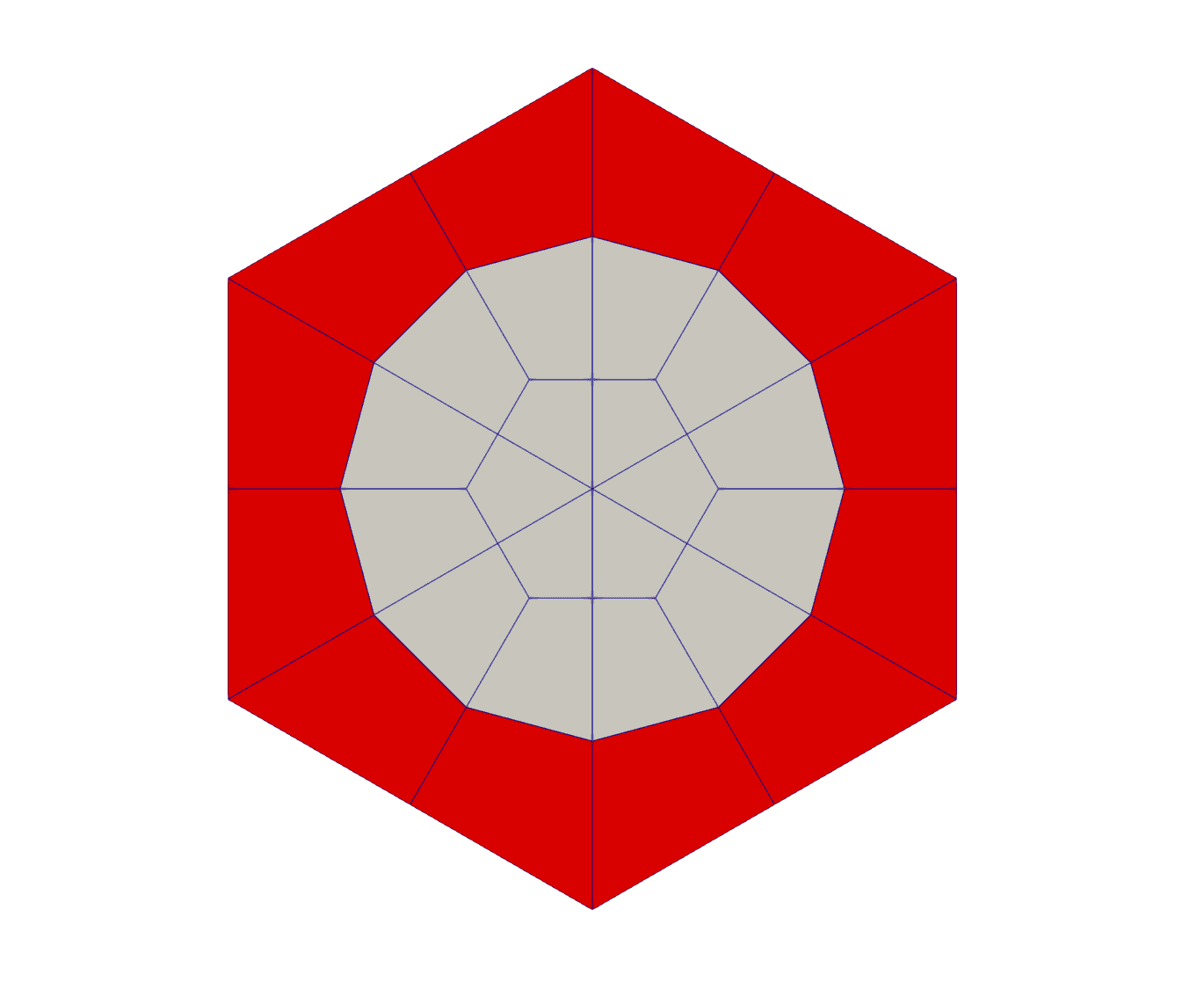
Figure 1: Fuel Pin Mesh
[Mesh]
  [fuel_pin_mesh]
    type = PolygonConcentricCircleMeshGenerator
    num_sides = ${pin_num_sides}
    num_sectors_per_side = ${pin_num_sectors_per_side_vector}
    background_block_ids = '${graphite_quad_block_id}'
    background_block_names = '${graphite_quad_block_name}'
    ring_intervals = '1'
    ring_radii = '${fuel_gap_radius}'
    ring_block_ids = '${fuel_quad_block_id}'
    ring_block_names = '${fuel_quad_block_name}'
    quad_center_elements = true
    create_inward_interface_boundaries = false
    create_outward_interface_boundaries = false
  []
[]Burnable Poison Pin
A mesh is generated that describes the burnable poison pin geometry. Each pin has six sides, with two sectors per side. Each pin has a radius of 0.5715cm. The pins form a hollow circle which has an interior gap radius of 0.635cm.
[Mesh]
  [burnable_poison_pin_mesh]
    type = PolygonConcentricCircleMeshGenerator
    # Define cell as hexagon
    num_sides = ${pin_num_sides}
    # Define number of elements on each side for the azimuthal discretization
    # This must be an even number
    num_sectors_per_side = ${pin_num_sectors_per_side_vector}
    # Define the block ID and name of the background block ID
    # The background block ID describes the area of the polygon outside of the rings
    background_block_ids = '${graphite_quad_block_id}'
    background_block_names = '${graphite_quad_block_name}'
    # Defines the number of ring blocks (based on the length of ring_intervals) and the number of spatial ring refinement for each of the ring blocks
    ring_intervals = '1'
    # First value describes the outer radius of the innermost ring and the inner radius of the next ring
    ring_radii = '${burnable_poison_gap_radius}'
    ring_block_ids = '${burnable_poison_quad_block_id}'
    ring_block_names = '${burnable_poison_quad_block_name}'
    # By using quad center elements we avoid having lots of element boundaries intersecting in the center of the pin.
    # Additionally, TRI and QUAD elements are not allowed to have the same block ID, so this allows us to have more of the same block IDs
    quad_center_elements = true
    create_inward_interface_boundaries = false
    create_outward_interface_boundaries = false
  []
[]Fuel Assembly
Second, two hexagonal fuel assembly meshes are then generated, one without the RSC channel and one with the RSC channel.
The assembly mesh without the RSC is composed of 4 burnable poison pin meshes, 143 fuel pin meshes, 121 large coolant channel meshes, 3 empty pin meshes, and 6 small coolant channel meshes.
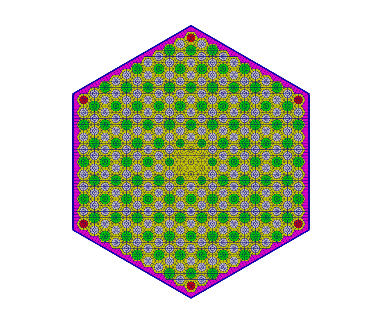
Figure 2: Fuel Assembly Mesh without RSC Channel
[Mesh]
  [fuel_assembly]
    type = PatternedHexMeshGenerator
    # 0 burnable_poison_pin_mesh
    # 1 fuel_pin_mesh
    # 2 large_coolant_channel_mesh
    # 3 empty_pin
    # 4 small_coolant_channel_mesh
    inputs = 'burnable_poison_pin_mesh fuel_pin_mesh large_coolant_channel_mesh empty_pin small_coolant_channel_mesh'
    pattern = '
                  0 1 2 1 1 2 1 1 2 1 0;
                 1 2 1 1 2 1 1 2 1 1 2 1;
                2 1 1 2 1 1 2 1 1 2 1 1 2;
               1 1 2 1 1 2 1 1 2 1 1 2 1 1;
              1 2 1 1 2 1 1 2 1 1 2 1 1 2 1;
             2 1 1 2 1 1 2 1 1 2 1 1 2 1 1 2;
            1 1 2 1 1 2 1 1 2 1 1 2 1 1 2 1 1;
           1 2 1 1 2 1 1 2 1 1 2 1 1 2 1 1 2 1;
          2 1 1 2 1 1 2 1 1 4 1 1 2 1 1 2 1 1 2;
         1 1 2 1 1 2 1 1 4 3 3 4 1 1 2 1 1 2 1 1;
        0 2 1 1 2 1 1 2 1 3 3 3 1 2 1 1 2 1 1 2 0;
         1 1 2 1 1 2 1 1 4 3 3 4 1 1 2 1 1 2 1 1;
          2 1 1 2 1 1 2 1 1 4 1 1 2 1 1 2 1 1 2;
           1 2 1 1 2 1 1 2 1 1 2 1 1 2 1 1 2 1;
            1 1 2 1 1 2 1 1 2 1 1 2 1 1 2 1 1;
             2 1 1 2 1 1 2 1 1 2 1 1 2 1 1 2;
              1 2 1 1 2 1 1 2 1 1 2 1 1 2 1;
               1 1 2 1 1 2 1 1 2 1 1 2 1 1;
                2 1 1 2 1 1 2 1 1 2 1 1 2;
                 1 2 1 1 2 1 1 2 1 1 2 1;
                  0 1 2 1 1 2 1 1 2 1 0'
    id_name = pin_id
    assign_type = cell
    pattern_boundary = hexagon
    hexagon_size = ${assembly_apothem}
    duct_sizes = ${duct_apothem}
    duct_intervals = 1
    duct_block_ids = '${assembly_helium_quad_block_id}'
    duct_block_names = '${assembly_helium_quad_block_name}'
    background_block_id = ${assembly_graphite_quad_block_id}
    background_block_name = ${assembly_graphite_quad_block_name}
    external_boundary_id = ${fuel_assembly_boundary_id}
    external_boundary_name = ${fuel_assembly_boundary_name}
    generate_core_metadata = true
    background_intervals = 1
  []
[]The assembly with the RSC is composed of 6 burnable poison pin meshes, 132 fuel pin mesh elements, 102 large coolant channel mesh elements, 7 empty pin mesh elements, 14 empty pin to delete (for the RSC) mesh elements, and 5 small coolant channel mesh elements.
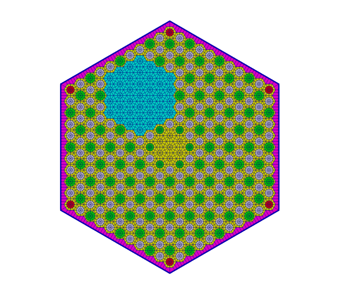
Figure 3: Fuel Assembly Mesh with RSC Channel
[Mesh]
  [fuel_assembly_with_rsc]
    type = PatternedHexMeshGenerator
    # 0 burnable_poison_pin_mesh
    # 1 fuel_pin_mesh
    # 2 large_coolant_channel_mesh
    # 3 empty_pin
    # 4 empty_pin_to_delete
    # 5 small_coolant_channel_mesh
    inputs = 'burnable_poison_pin_mesh fuel_pin_mesh large_coolant_channel_mesh empty_pin empty_pin_to_delete small_coolant_channel_mesh'
    pattern = '
                  0 1 2 1 1 2 1 1 2 1 0;
                 1 2 1 1 2 1 1 2 1 1 2 1;
                2 1 1 2 1 1 2 1 1 2 1 1 2;
               1 1 2 1 1 2 1 1 2 1 1 2 1 1;
              1 2 1 1 2 1 1 2 1 1 4 4 4 4 1;
             2 1 1 2 1 1 2 1 1 2 4 4 4 4 4 2;
            1 1 2 1 1 2 1 1 2 1 4 4 4 4 4 4 1;
           1 2 1 1 2 1 1 2 1 1 4 4 4 4 4 4 4 1;
          2 1 1 2 1 1 2 1 1 5 1 4 4 4 4 4 4 1 2;
         1 1 2 1 1 2 1 1 5 3 3 5 4 4 4 4 4 2 1 1;
        0 2 1 1 2 1 1 2 1 3 3 3 1 4 4 4 4 1 1 2 0;
         1 1 2 1 1 2 1 1 5 3 3 5 1 1 2 1 1 2 1 1;
          2 1 1 2 1 1 2 1 1 5 1 1 2 1 1 2 1 1 2;
           1 2 1 1 2 1 1 2 1 1 2 1 1 2 1 1 2 1;
            1 1 2 1 1 2 1 1 2 1 1 2 1 1 2 1 1;
             2 1 1 2 1 1 2 1 1 2 1 1 2 1 1 2;
              1 2 1 1 2 1 1 2 1 1 2 1 1 2 1;
               1 1 2 1 1 2 1 1 2 1 1 2 1 1;
                2 1 1 2 1 1 2 1 1 2 1 1 2;
                 1 2 1 1 2 1 1 2 1 1 2 1;
                  0 1 2 1 1 2 1 1 2 1 0'
    id_name = pin_id
    assign_type = cell
    pattern_boundary = hexagon
    hexagon_size = ${assembly_apothem}
    duct_sizes = ${duct_apothem}
    duct_intervals = 1
    duct_block_ids = '${assembly_helium_quad_block_id}'
    duct_block_names = '${assembly_helium_quad_block_name}'
    background_block_id = ${assembly_graphite_quad_block_id}
    background_block_name = ${assembly_graphite_quad_block_name}
    external_boundary_id = ${fuel_assembly_boundary_id}
    external_boundary_name = ${fuel_assembly_boundary_name}
    generate_core_metadata = true
    background_intervals = 1
  []
[]The hexagonal fuel assembly with RSC then undergoes many modifications. First, the pin cells are deleted. Then, a new block ID is assigned to the holes left by the deletion and the holes are remeshed. The boundary of the RSC channel is then generated and stitched back into the fuel assembly mesh. Finally, the holes and the assembly meshes are stitched together.
  [delete_pins_for_rsc]
    type = BlockDeletionGenerator
    input = fuel_assembly_with_rsc
    block = '${to_delete_block_name}'
    new_boundary = 'rsc_area_assembly_boundary'
  []
  # The deletion has created a void where the deleted pin cells were. We now assign a block ID to the deleted area
  [rebuild_rsc_void]
    type = LowerDBlockFromSidesetGenerator
    input = delete_pins_for_rsc
    sidesets = 'rsc_area_assembly_boundary'
    new_block_id = ${temp_block_id}
    new_block_name = ${temp_block_name}
  []
  # Next we mesh the area with the new block ID, removing the void
  [convert_rsc_void_to_mesh]
    type = BlockToMeshConverterGenerator
    input = rebuild_rsc_void
    target_blocks = ${temp_block_name}
  []
  # Now ParsedCurveGenerator can be used to generate the boundary of the RSC hole
  # Diameter of 9.525 cm specified in Table 3
  # Center of hole distance of 3.841 in (9.756 cm)
  [rsc_hole]
    type = ParsedCurveGenerator
    x_formula = '${rsc_hole_radius}*cos(t) + ${rsc_hole_xpos}'
    y_formula = '${rsc_hole_radius}*sin(t) + ${rsc_hole_ypos}'
    section_bounding_t_values = '0.0 ${fparse 2.0*pi}'
    nums_segments = '${rsc_hole_num_segments}'
    is_closed_loop = true
  []
  # Next we use XYDelaunayGenerator (XYDG) to carve the hole in the area of the pin cells we designated for the RSC hole
  [rsc_area_with_hole]
    type = XYDelaunayGenerator
    boundary = 'convert_rsc_void_to_mesh'
    holes = 'rsc_hole'
    hole_boundaries = 'heterogeneous_hole_boundary'
    add_nodes_per_boundary_segment = 0
    output_boundary = 10010 # xy_output_boundary
    refine_boundary = false
    smooth_triangulation = true
    desired_area = 0.5
    output_subdomain_name = ${graphite_tri_block_id}
  []
  # Now that we have the pin cell area with the RSC hole carved in it
  # we now stitch this pin cell area back into the fuel assembly
  # which the pin cell area was deleted from.
  # Note that the RSC hole carved is currently unmeshed (i.e. void)
  [fuel_assembly_with_rsc_hole_void]
    type = StitchedMeshGenerator
    inputs = 'delete_pins_for_rsc rsc_area_with_hole'
    stitch_boundaries_pairs = 'rsc_area_assembly_boundary 10010'
  []
  # Since we want the RSC hole meshed we need to get the hole boundary and use XYDG to mesh it
  [mesh_rsc_hole_for_fuel_assembly]
    type = XYDelaunayGenerator
    boundary = 'fuel_assembly_with_rsc_hole_void'
    add_nodes_per_boundary_segment = 0
    input_boundary_names = heterogeneous_hole_boundary # xy_output_boundary
    refine_boundary = false
    smooth_triangulation = true
    output_subdomain_name = ${rsc_hole_tri_block_id}
    output_boundary = to_stitch_third
    desired_area = ${xydg_rsc_hole_desired_area}
  []
# Now we must stitch the meshed RSC hole to the fuel assembly with the RSC voidThe RSC is oriented in 6 different positions, so lastly all 6 variations are generated using transformations. Each transformation strips metadata from the input mesh, so the metadata must be re-added after each rotation.
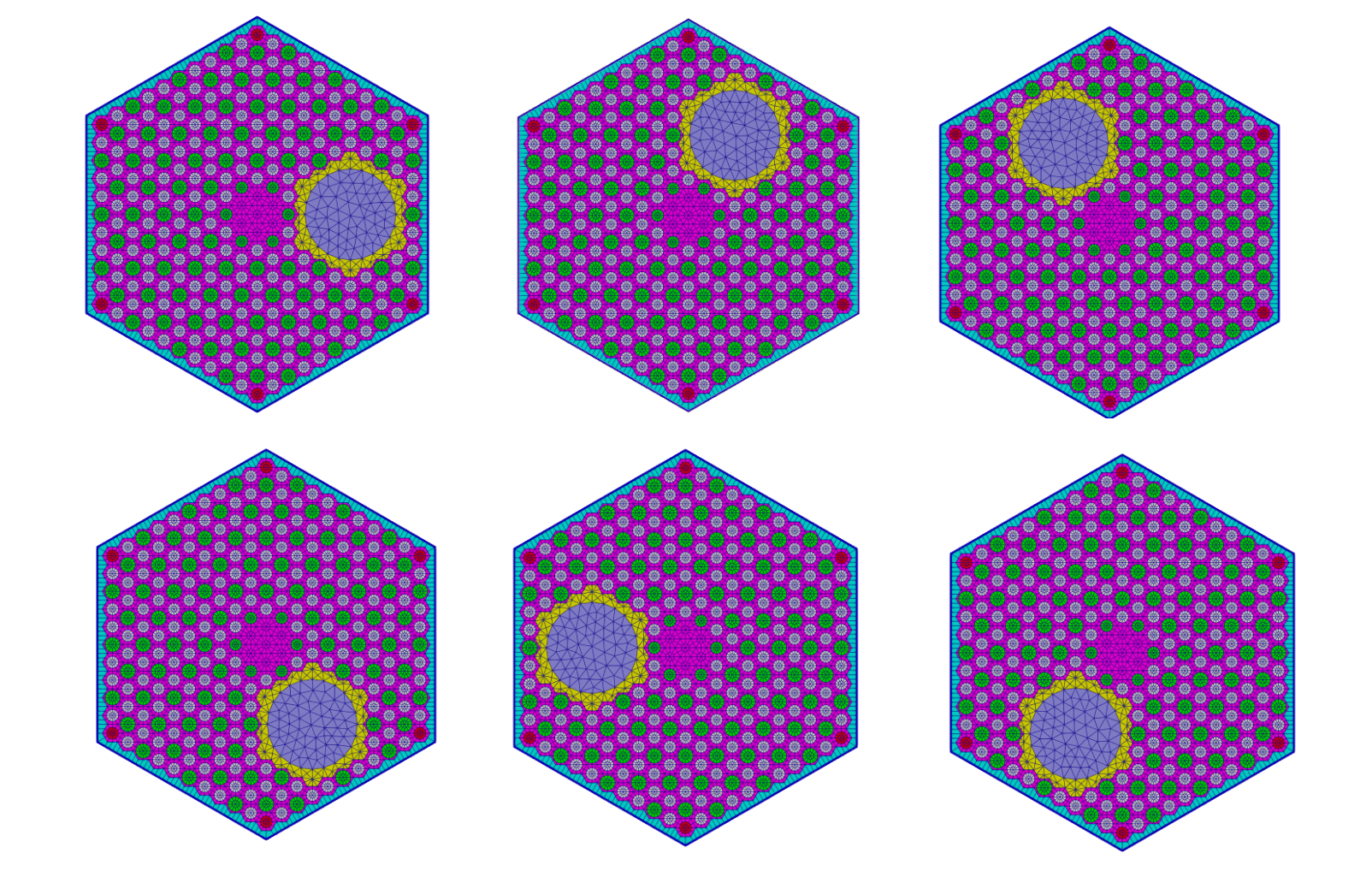
Figure 4: Fuel Assembly Mesh Variations
The following code is repeated for each transformation.
  [fuel_assembly_with_rsc_1]
    type = AddMetaDataGenerator
    input = fuel_assembly_w_rsc_stitched
  []
  # Because the RSC is oriented in 6 different positions, we need to generate all 6 rotated variations of the assembly.
  # We have already generated 1 so far, so now we need to use rotational transformations in order to generate the other 5
  # Since transformations will strip any metadata from the input mesh, we can use the stitched mesh, rotate it, then add the metadata
  # We title the transformations based on the side of the assembly the RSC is on.
  # Side indices can be found at https://mooseframework.inl.gov/source/meshgenerators/PolygonConcentricCircleMeshGenerator.html
  # Fuel Assembly w/RSC Hole Side 0
  [transform_fuel_assembly_w_rsc_0]
    type = TransformGenerator
    input = fuel_assembly_w_rsc_stitched
    transform = ROTATE
    vector_value = '-60 0 0'
[]Reflector Assembly
The base of the assembly is generated first. Then, the interior is deleted in order to re-mesh the assembly to border the fuel assemblies without leaving long, thin elements that intersect in the center of the hexagon.
  [reflector_assembly_base]
    type = HexagonConcentricCircleAdaptiveBoundaryMeshGenerator
    hexagon_size_style = apothem
    hexagon_size = ${assembly_apothem}
    duct_sizes = ${duct_apothem}
    duct_sizes_style = apothem
    duct_intervals = 1
    background_block_ids = '${to_delete_block_id}'
    background_block_names = '${to_delete_block_name}'
    duct_block_ids = '${helium_quad_block_id}'
    duct_block_names = '${helium_quad_block_id}'
    num_sectors_per_side = '${num_non_fuel_assembly_sectors} ${num_non_fuel_assembly_sectors} ${num_non_fuel_assembly_sectors} ${num_non_fuel_assembly_sectors} ${num_non_fuel_assembly_sectors} ${num_non_fuel_assembly_sectors}'
  []
  # Delete the reflector assembly interior in preparation for re-meshing
  [delete_reflector_assembly_interior]
    type = BlockDeletionGenerator
    input = reflector_assembly_base
    block = '${to_delete_block_name}'
    new_boundary = 'deleted_reflector_boundary_no_adapt'
  []
  # Define a block around the deleted reflector assembly interior
  [rebuild_reflector_assembly_interior]
    type = LowerDBlockFromSidesetGenerator
    input = delete_reflector_assembly_interior
    sidesets = 'deleted_reflector_boundary_no_adapt'
    new_block_id = ${temp_block_id}
    new_block_name = ${temp_block_name}
  []
  # Remesh the reflector assembly interior using the newly-defined block
  [remesh_reflector_assembly_interior]
    type = BlockToMeshConverterGenerator
    input = rebuild_reflector_assembly_interior
    target_blocks = ${temp_block_name}
  []
  # Meshes the reflector assembly interior using triangular elements
  [triangulate_reflector_assembly_interior]
    type = XYDelaunayGenerator
    boundary = 'remesh_reflector_assembly_interior'
    add_nodes_per_boundary_segment = 0
    output_boundary = 11000 # xy_output_boundary
    refine_boundary = false
    smooth_triangulation = true
    desired_area = ${xydg_reflector_assembly_desired_area}
    output_subdomain_name = ${graphite_tri_block_id}
  []
  # Stitches the reflector assembly duct back together with the now triangulated reflector assembly interior
  [stitch_reflector_assembly]
    type = StitchedMeshGenerator
    inputs = 'delete_reflector_assembly_interior triangulate_reflector_assembly_interior'
    stitch_boundaries_pairs = 'deleted_reflector_boundary_no_adapt 11000'
  []
# Once again we need to add the metadata to the assembly so it can be used by Pattern Mesh GeneratorsA reflector assembly which borders fuel assemblies on 3 sides must be adapted by deleting, rebuilding, remeshing, triangulating, stitching, and reapplying the metadata to the interior.
  [reflector_assembly_base_0_1_2]
    type = HexagonConcentricCircleAdaptiveBoundaryMeshGenerator
    hexagon_size_style = apothem
    hexagon_size = ${assembly_apothem}
    duct_sizes = ${duct_apothem}
    duct_sizes_style = apothem
    duct_intervals = 1
    background_block_ids = '${to_delete_block_id}'
    background_block_names = '${to_delete_block_name}'
    duct_block_ids = '${helium_quad_block_id}'
    duct_block_names = '${helium_quad_block_name}'
    sides_to_adapt = '0 1 2'
    meshes_to_adapt_to = 'fuel_assembly fuel_assembly fuel_assembly'
    num_sectors_per_side = '${num_fuel_assembly_sectors} ${num_fuel_assembly_sectors} ${num_fuel_assembly_sectors} ${num_non_fuel_assembly_sectors} ${num_non_fuel_assembly_sectors} ${num_non_fuel_assembly_sectors}'
  []
  [delete_reflector_assembly_interior_0_1_2]
    type = BlockDeletionGenerator
    input = reflector_assembly_base_0_1_2
    block = '${to_delete_block_name}'
    new_boundary = 'deleted_reflector_boundary_adapt_0_1_2'
  []
  [rebuild_reflector_assembly_interior_0_1_2]
    type = LowerDBlockFromSidesetGenerator
    input = delete_reflector_assembly_interior_0_1_2
    sidesets = 'deleted_reflector_boundary_adapt_0_1_2'
    new_block_id = ${temp_block_id}
    new_block_name = ${temp_block_name}
  []
  [remesh_reflector_assembly_interior_0_1_2]
    type = BlockToMeshConverterGenerator
    input = rebuild_reflector_assembly_interior_0_1_2
    target_blocks = ${temp_block_name}
  []
  [triangulate_reflector_assembly_interior_0_1_2]
    type = XYDelaunayGenerator
    boundary = 'remesh_reflector_assembly_interior_0_1_2'
    add_nodes_per_boundary_segment = 0
    output_boundary = 11001 # xy_output_boundary
    refine_boundary = false
    smooth_triangulation = true
    desired_area = ${xydg_reflector_assembly_desired_area}
    output_subdomain_name = ${graphite_tri_block_id}
  []
  [stitch_reflector_assembly_0_1_2]
    type = StitchedMeshGenerator
    inputs = 'delete_reflector_assembly_interior_0_1_2 triangulate_reflector_assembly_interior_0_1_2'
    stitch_boundaries_pairs = 'deleted_reflector_boundary_adapt_0_1_2 11001'
[]Because of the MHTGR geometry, this must be done for 6 different variations, notably through rotations in order for each reflector assembly to border fuel assemblies on 3 sides.
The following code is repeated for each transformation.
  [transform_reflector_assembly_1_2_3]
    type = TransformGenerator
    input = stitch_reflector_assembly_0_1_2
    transform = ROTATE
    vector_value = '60 0 0'
[]The entire process of adapting the reflector assembly and generating the 6 different variations is then repeated for the reflector assemblies with border fuel assemblies on only 2 sides.
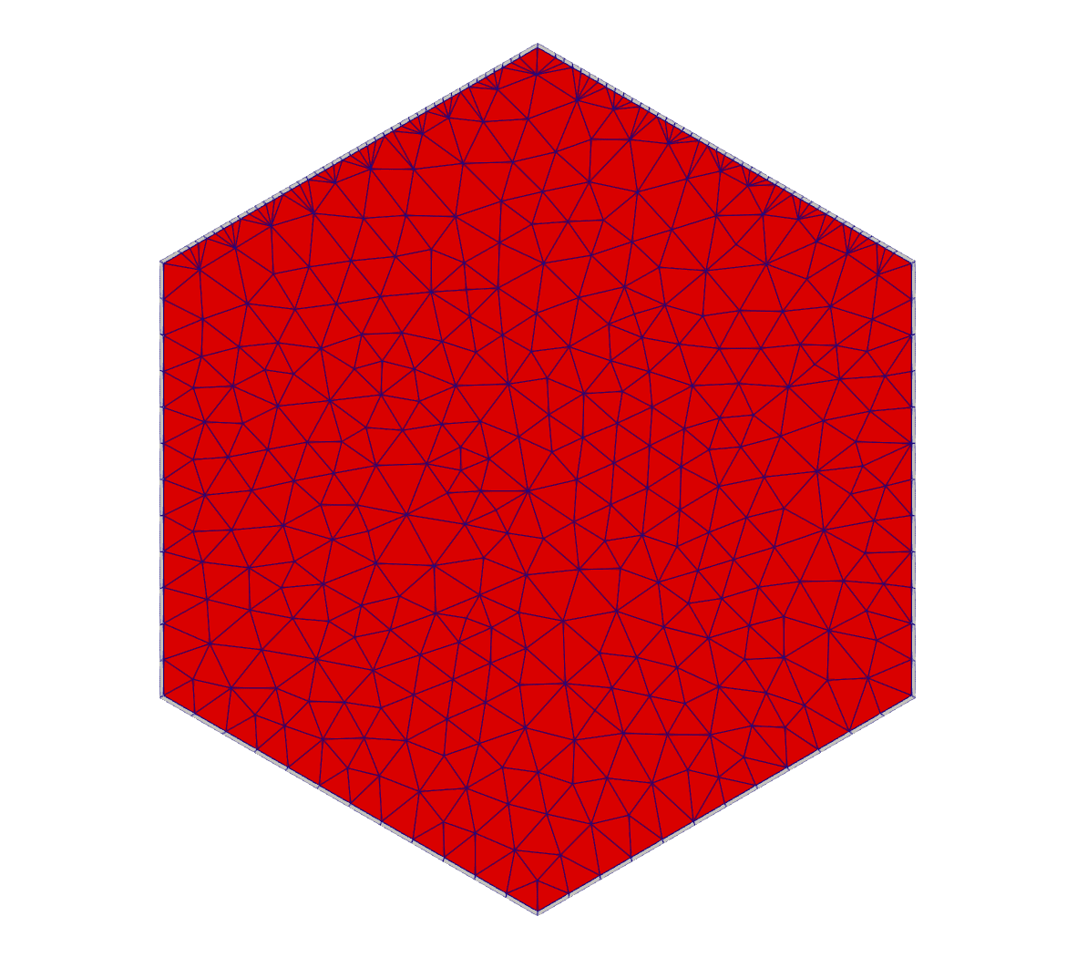
Figure 5: Reflector Assembly Mesh that borders Fuel Assemblies on 2 sides.
  [reflector_assembly_base_0_1]
    type = HexagonConcentricCircleAdaptiveBoundaryMeshGenerator
    hexagon_size_style = apothem
    hexagon_size = ${assembly_apothem}
    duct_sizes = ${duct_apothem}
    duct_sizes_style = apothem
    duct_intervals = 1
    background_block_ids = '${to_delete_block_id}'
    background_block_names = '${to_delete_block_name}'
    duct_block_ids = '${helium_quad_block_id}'
    duct_block_names = '${helium_quad_block_name}'
    sides_to_adapt = '0 1'
    meshes_to_adapt_to = 'fuel_assembly fuel_assembly'
    num_sectors_per_side = '${num_fuel_assembly_sectors} ${num_fuel_assembly_sectors} ${num_non_fuel_assembly_sectors} ${num_non_fuel_assembly_sectors} ${num_non_fuel_assembly_sectors} ${num_non_fuel_assembly_sectors}'
  []
  [delete_reflector_assembly_interior_0_1]
    type = BlockDeletionGenerator
    input = reflector_assembly_base_0_1
    block = '${to_delete_block_name}'
    new_boundary = 'deleted_reflector_boundary_adapt_0_1'
  []
  [rebuild_reflector_assembly_interior_0_1]
    type = LowerDBlockFromSidesetGenerator
    input = delete_reflector_assembly_interior_0_1
    sidesets = 'deleted_reflector_boundary_adapt_0_1'
    new_block_id = ${temp_block_id}
    new_block_name = ${temp_block_name}
  []
  [remesh_reflector_assembly_interior_0_1]
    type = BlockToMeshConverterGenerator
    input = rebuild_reflector_assembly_interior_0_1
    target_blocks = ${temp_block_name}
  []
  [triangulate_reflector_assembly_interior_0_1]
    type = XYDelaunayGenerator
    boundary = 'remesh_reflector_assembly_interior_0_1'
    add_nodes_per_boundary_segment = 0
    output_boundary = 11002 # xy_output_boundary
    refine_boundary = false
    smooth_triangulation = true
    desired_area = ${xydg_reflector_assembly_desired_area}
    output_subdomain_name = ${graphite_tri_block_id}
  []
  [stitch_reflector_assembly_0_1]
    type = StitchedMeshGenerator
    inputs = 'delete_reflector_assembly_interior_0_1 triangulate_reflector_assembly_interior_0_1'
    stitch_boundaries_pairs = 'deleted_reflector_boundary_adapt_0_1 11002'
  []
  [reflector_assembly_0_1]
    type = AddMetaDataGenerator
    input = stitch_reflector_assembly_0_1
  []
  # Now we rotate the reflector meshes again to cover all 6 directions
  [transform_reflector_assembly_1_2]
    type = TransformGenerator
    input = stitch_reflector_assembly_0_1
    transform = ROTATE
    vector_value = '60 0 0'
[]The process is repeated again for the reflector assemblies which have a control rod (CR) hole in them and border 2 fuel assemblies. These assemblies are also reflected, so we need 12 permutations, not 6.
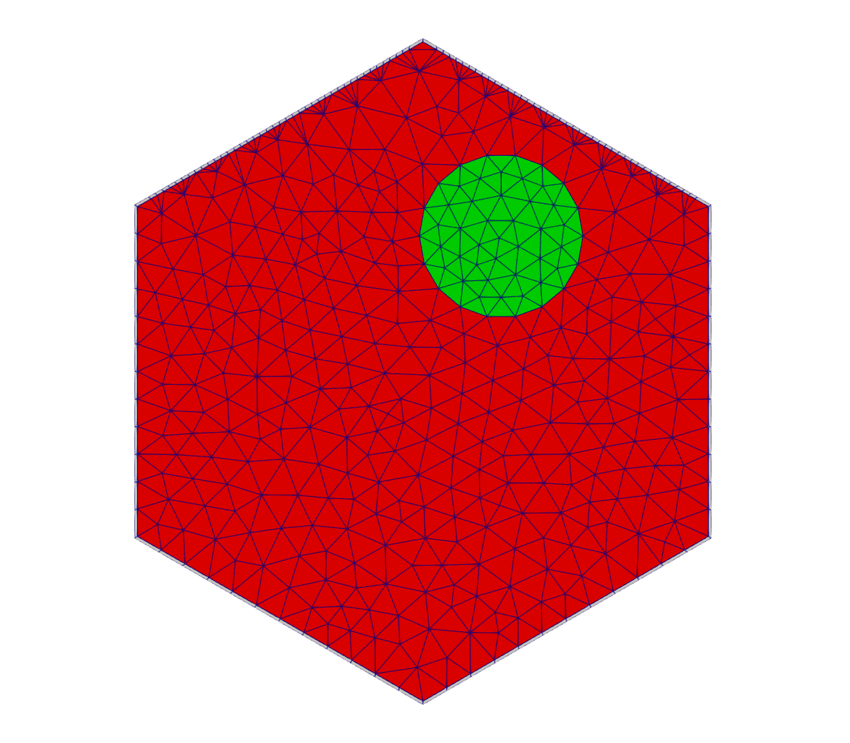
Figure 6: Reflector Assembly Mesh with CR hole that borders Fuel Assemblies on 2 sides.
  [reflector_assembly_w_cr_base_0_1]
    type = HexagonConcentricCircleAdaptiveBoundaryMeshGenerator
    hexagon_size_style = apothem
    hexagon_size = ${assembly_apothem}
    duct_sizes = ${duct_apothem}
    duct_sizes_style = apothem
    duct_intervals = 1
    background_block_ids = '${to_delete_block_id}'
    background_block_names = '${to_delete_block_name}'
    duct_block_ids = '${helium_quad_block_id}'
    duct_block_names = '${helium_quad_block_name}'
    sides_to_adapt = '0 1'
    num_sectors_per_side = '${num_fuel_assembly_sectors} ${num_fuel_assembly_sectors} ${num_non_fuel_assembly_sectors} ${num_non_fuel_assembly_sectors} ${num_non_fuel_assembly_sectors} ${num_non_fuel_assembly_sectors}'
    meshes_to_adapt_to = 'fuel_assembly fuel_assembly'
    external_boundary_id = 1776
    external_boundary_name = hole_mesh_0_1_w_hole_boundary
  []
  # Delete the interior of the reflector assembly
  [delete_reflector_assembly_interior_w_cr_0_1]
    type = BlockDeletionGenerator
    input = reflector_assembly_w_cr_base_0_1
    block = '${to_delete_block_name}'
    new_boundary = '870'
  []
  # Assign a block ID to the deleted area
  [rebuild_reflector_assembly_interior_w_cr_0_1]
    type = LowerDBlockFromSidesetGenerator
    input = delete_reflector_assembly_interior_w_cr_0_1
    sidesets = '870'
    new_block_id = ${temp_block_id}
    new_block_name = ${temp_block_name}
  []
  # Remesh the block ID of the deleted area
  [remesh_reflector_assembly_interior_w_cr_0_1]
    type = BlockToMeshConverterGenerator
    input = rebuild_reflector_assembly_interior_w_cr_0_1
    target_blocks = ${temp_block_name}
  []
  # Define the CR hole in the reflector assembly
  # Diameter of 10.2 cm specified below Figure 6
  # Center of hole is 3.841 inches (9.756 cm) from the center of the assembly
  [cr_hole]
    type = ParsedCurveGenerator
    x_formula = '${cr_hole_radius}*cos(t) + ${cr_hole_xpos}'
    y_formula = '${cr_hole_radius}*sin(t) + ${cr_hole_ypos}'
    section_bounding_t_values = '0.0 ${fparse 2.0*pi}'
    # can increase for better element refinement along the assembly boundary
    nums_segments = '${cr_hole_num_segments}'
    is_closed_loop = true
  []
  # Now we mesh/fill the CR hole in the reflector assembly
  [fill_reflector_assembly_cr_hole_0_1]
    type = XYDelaunayGenerator
    boundary = 'cr_hole'
    add_nodes_per_boundary_segment = 0
    refine_boundary = false
    smooth_triangulation = true
    output_subdomain_name = ${cr_hole_tri_block_id}
    output_boundary = 871
    desired_area = ${xydg_cr_hole_desired_area}
  []
  # Triangulate the mesh of the interior reflector assembly except for the CR hole which remains a void
  [triangulate_reflector_assembly_w_cr_hole_0_1]
    type = XYDelaunayGenerator
    boundary = 'remesh_reflector_assembly_interior_w_cr_0_1'
    holes = 'fill_reflector_assembly_cr_hole_0_1'
    stitch_holes = 'true'
    refine_holes = 'false'
    add_nodes_per_boundary_segment = 0
    output_boundary = 10000 # xy_output_boundary
    refine_boundary = false
    smooth_triangulation = true
    desired_area = ${xydg_reflector_assembly_desired_area}
    output_subdomain_name = ${graphite_tri_block_id}
  []
  # Stitch the reflector assembly interior with the reflector assembly duct
  [stitch_reflector_assembly_cr_hole_filled_0_1]
    type = StitchedMeshGenerator
    inputs = 'delete_reflector_assembly_interior_w_cr_0_1 triangulate_reflector_assembly_w_cr_hole_0_1'
    stitch_boundaries_pairs = '870 10000'
  []
# Now add metadata for Pattern Mesh GeneratorThe following code is repeated for each of the 12 permutations.
[Mesh]
  [transform_reflector_assembly_w_cr_hole_0_1_reflected]
    type = TransformGenerator
    input = stitch_reflector_assembly_cr_hole_filled_0_1
    transform = ROTATE
    vector_value = '180 180 0'
  []
[][Mesh]
[reflector_assembly_w_cr_hole_0_1_reflected]
type = AddMetaDataGenerator
input = transform_reflector_assembly_w_cr_hole_0_1_reflected
[]
[]Lastly, the process is repeated for the reflector assemblies which have a control rod (CR) hole in them and border only 1 fuel assembly.
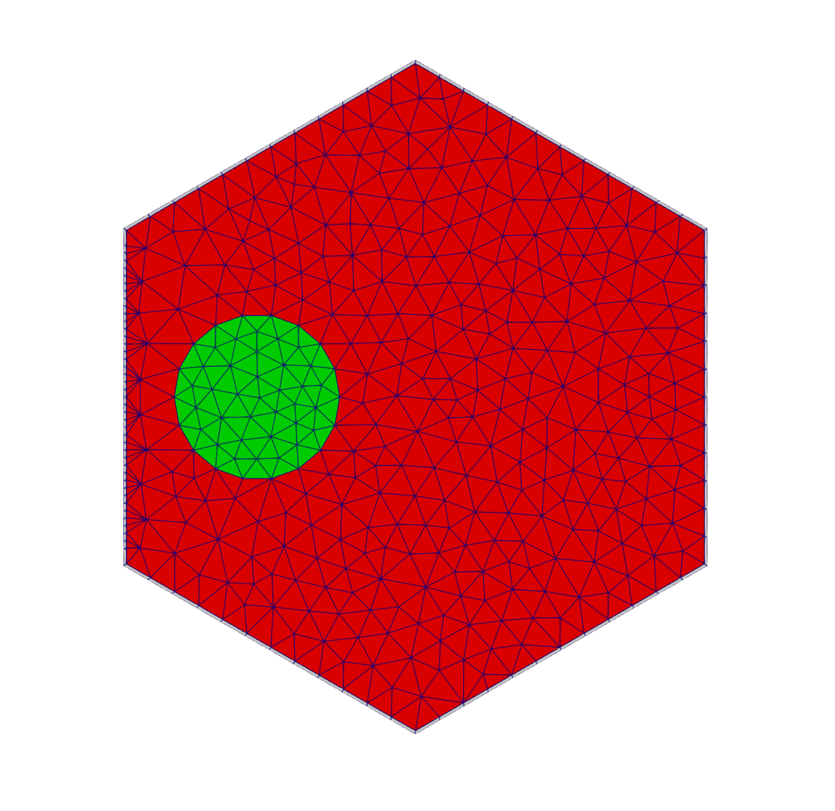
Figure 7: Reflector Assembly Mesh with CR hole that borders Fuel Assembly on 1 side.
[Mesh]
  [reflector_assembly_w_cr_base_0]
    type = HexagonConcentricCircleAdaptiveBoundaryMeshGenerator
    hexagon_size_style = apothem
    hexagon_size = ${assembly_apothem}
    duct_sizes = ${duct_apothem}
    duct_sizes_style = apothem
    duct_intervals = 1
    background_block_ids = '${to_delete_block_id}'
    background_block_names = '${to_delete_block_name}'
    duct_block_ids = '${helium_quad_block_id}'
    duct_block_names = '${helium_quad_block_name}'
    sides_to_adapt = '0'
    num_sectors_per_side = '${num_fuel_assembly_sectors} ${num_non_fuel_assembly_sectors} ${num_non_fuel_assembly_sectors} ${num_non_fuel_assembly_sectors} ${num_non_fuel_assembly_sectors} ${num_non_fuel_assembly_sectors}'
    meshes_to_adapt_to = 'fuel_assembly'
    external_boundary_id = 1812
    external_boundary_name = hole_mesh_0_w_hole_boundary
  []
[][Mesh]
[delete_reflector_assembly_interior_w_cr_0]
type = BlockDeletionGenerator
input = reflector_assembly_w_cr_base_0
block = '${to_delete_block_name}'
new_boundary = 'deleted_hole_mesh_0_boundary'
[]
[][Mesh]
[rebuild_reflector_assembly_interior_w_cr_0]
type = LowerDBlockFromSidesetGenerator
input = delete_reflector_assembly_interior_w_cr_0
sidesets = 'deleted_hole_mesh_0_boundary'
new_block_id = ${temp_block_id}
new_block_name = ${temp_block_name}
[]
[][Mesh]
[remesh_reflector_assembly_interior_w_cr_0]
type = BlockToMeshConverterGenerator
input = rebuild_reflector_assembly_interior_w_cr_0
target_blocks = ${temp_block_name}
[]
[][Mesh]
[triangulate_reflector_assembly_w_cr_hole_0]
type = XYDelaunayGenerator
boundary = 'remesh_reflector_assembly_interior_w_cr_0'
holes = 'cr_hole'
hole_boundaries = 'homogeneous_hole_boundary_second'
add_nodes_per_boundary_segment = 0
output_boundary = 10001 # xy_output_boundary
refine_boundary = false
smooth_triangulation = true
desired_area = ${xydg_reflector_assembly_desired_area}
output_subdomain_name = ${graphite_tri_block_id}
[]
[][Mesh]
[stitch_reflector_assembly_w_cr_hole_0]
type = StitchedMeshGenerator
inputs = 'delete_reflector_assembly_interior_w_cr_0 triangulate_reflector_assembly_w_cr_hole_0'
stitch_boundaries_pairs = 'deleted_hole_mesh_0_boundary 10001'
[]
[][Mesh]
[fill_reflector_assembly_cr_hole_0]
type = XYDelaunayGenerator
boundary = 'stitch_reflector_assembly_w_cr_hole_0'
add_nodes_per_boundary_segment = 0
input_boundary_names = homogeneous_hole_boundary_second # xy_output_boundary
refine_boundary = false
smooth_triangulation = true
output_subdomain_name = ${cr_hole_tri_block_id}
output_boundary = to_stitch_second
desired_area = ${xydg_cr_hole_desired_area}
[]
[][Mesh]
[stitch_reflector_assembly_cr_hole_filled_0]
type = StitchedMeshGenerator
inputs = 'stitch_reflector_assembly_w_cr_hole_0 fill_reflector_assembly_cr_hole_0'
stitch_boundaries_pairs = 'homogeneous_hole_boundary_second to_stitch_second'
[]
[][Mesh]
[reflector_assembly_w_cr_hole_0]
type = AddMetaDataGenerator
input = stitch_reflector_assembly_cr_hole_filled_0
[]
[]The following code is repeated for each of the 6 permutations.
[Mesh]
  [transform_reflector_assembly_w_cr_hole_1]
    type = TransformGenerator
    input = stitch_reflector_assembly_cr_hole_filled_0
    transform = ROTATE
    vector_value = '60 0 0'
  []
[][Mesh]
[reflector_assembly_w_cr_hole_1]
type = AddMetaDataGenerator
input = transform_reflector_assembly_w_cr_hole_1
[]
[]Assembly to Remove
The last step of generating the core mesh is to create an assembly with a unique block ID that can be removed from the mesh later; this ensures that the final core is not required to have a perfect hexagonal pattern and can have one assembly removed in each corner.
[Mesh]
  [assembly_to_remove]
    type = HexagonConcentricCircleAdaptiveBoundaryMeshGenerator
    hexagon_size_style = apothem
    hexagon_size = ${assembly_apothem}
    background_block_ids = '${to_delete_block_id}'
    background_block_names = '${to_delete_block_name}'
    num_sectors_per_side = '${num_non_fuel_assembly_sectors} ${num_non_fuel_assembly_sectors} ${num_non_fuel_assembly_sectors} ${num_non_fuel_assembly_sectors} ${num_non_fuel_assembly_sectors} ${num_non_fuel_assembly_sectors}'
  []
[]Final Assembly
All of the smaller, previously generated assembly meshes are used as inputs and are assembled into a patterned hexagonal lattice 2D mesh.
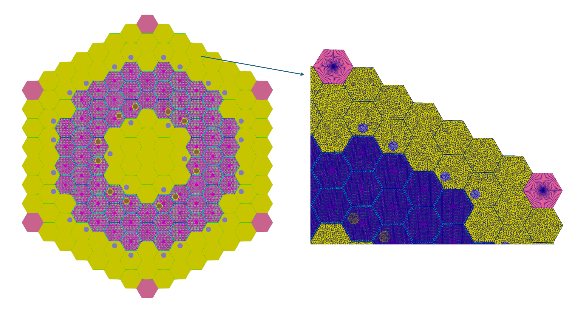
Figure 8: Hexagonal core mesh featuring close up of core assembly meshes
[Mesh]
  [hex_core]
    type = PatternedHexMeshGenerator
    # 00 reflector_assembly
    # 01 reflector_assembly_0_1_2
    # 02 reflector_assembly_1_2_3
    # 03 reflector_assembly_2_3_4
    # 04 reflector_assembly_3_4_5
    # 05 reflector_assembly_4_5_0
    # 06 reflector_assembly_5_0_1
    # 07 reflector_assembly_w_cr_hole_0_1_reflected
    # 08 reflector_assembly_w_cr_hole_1_2_reflected
    # 09 reflector_assembly_w_cr_hole_2_3_reflected
    # 10 reflector_assembly_w_cr_hole_3_4_reflected
    # 11 reflector_assembly_w_cr_hole_4_5_reflected
    # 12 reflector_assembly_w_cr_hole_5_0_reflected
    # 13 fuel_assembly
    # 14 reflector_assembly_0_1
    # 15 reflector_assembly_1_2
    # 16 reflector_assembly_2_3
    # 17 reflector_assembly_3_4
    # 18 reflector_assembly_4_5
    # 19 reflector_assembly_5_0
    # 20 reflector_assembly_w_cr_hole_0
    # 21 reflector_assembly_w_cr_hole_1
    # 22 reflector_assembly_w_cr_hole_2
    # 23 reflector_assembly_w_cr_hole_3
    # 24 reflector_assembly_w_cr_hole_4
    # 25 reflector_assembly_w_cr_hole_5
    # 26 assembly_to_remove
    # 27 reflector_assembly_w_cr_hole_0_1
    # 28 reflector_assembly_w_cr_hole_5_0
    # 29 reflector_assembly_w_cr_hole_4_5
    # 30 reflector_assembly_w_cr_hole_3_4
    # 31 reflector_assembly_w_cr_hole_2_3
    # 32 reflector_assembly_w_cr_hole_1_2
    # 33 fuel_assembly_w_rsc_0
    # 34 fuel_assembly_with_rsc_1
    # 35 fuel_assembly_w_rsc_2
    # 36 fuel_assembly_w_rsc_3
    # 37 fuel_assembly_w_rsc_4
    # 38 fuel_assembly_w_rsc_5
    inputs = 'reflector_assembly
              reflector_assembly_0_1_2
              reflector_assembly_1_2_3
              reflector_assembly_2_3_4
              reflector_assembly_3_4_5
              reflector_assembly_4_5_0
              reflector_assembly_5_0_1
              reflector_assembly_w_cr_hole_0_1_reflected
              reflector_assembly_w_cr_hole_1_2_reflected
              reflector_assembly_w_cr_hole_2_3_reflected
              reflector_assembly_w_cr_hole_3_4_reflected
              reflector_assembly_w_cr_hole_4_5_reflected
              reflector_assembly_w_cr_hole_5_0_reflected
              fuel_assembly
              reflector_assembly_0_1
              reflector_assembly_1_2
              reflector_assembly_2_3
              reflector_assembly_3_4
              reflector_assembly_4_5
              reflector_assembly_5_0
              reflector_assembly_w_cr_hole_0
              reflector_assembly_w_cr_hole_1
              reflector_assembly_w_cr_hole_2
              reflector_assembly_w_cr_hole_3
              reflector_assembly_w_cr_hole_4
              reflector_assembly_w_cr_hole_5
              assembly_to_remove
              reflector_assembly_w_cr_hole_0_1
              reflector_assembly_w_cr_hole_5_0
              reflector_assembly_w_cr_hole_4_5
              reflector_assembly_w_cr_hole_3_4
              reflector_assembly_w_cr_hole_2_3
              reflector_assembly_w_cr_hole_1_2
              fuel_assembly_w_rsc_0
              fuel_assembly_with_rsc_1
              fuel_assembly_w_rsc_2
              fuel_assembly_w_rsc_3
              fuel_assembly_w_rsc_4
              fuel_assembly_w_rsc_5'
    pattern = '
                26  00  00  00  00  00  00  26;
              00  00  24  10  17  30  23  00  00;
            00  24  04  13  13  13  13  03  23  00;
          00  29  13  13  13  13  13  13  13  09  00;
        00  18  13  13  13  38  38  13  13  13  16  00;
      00  11  13  13  33  01  27  06  37  13  13  31  00;
    00  25  13  13  33  32  00  00  28  37  13  13  22  00;
  26  00  05  13  13  02  00  00  00  05  13  13  02  00  26;
    00  25  13  13  34  31  00  00  29  36  13  13  22  00;
      00  28  13  13  34  03  30  04  36  13  13  08  00;
        00  19  13  13  13  35  35  13  13  13  15  00;
          00  12  13  13  13  13  13  13  13  32  00;
            00  20  06  13  13  13  13  01  21  00;
              00  00  20  27  14  07  21  00  00;
                26  00  00  00  00  00  00  26'
    id_name = assembly_id
    assign_type = cell
    pattern_boundary = none
    external_boundary_id = 33
    external_boundary_name = 'radial_edge_boundary'
    generate_core_metadata = true
  []
[]An additional ring boundary is added to the 2D mesh.
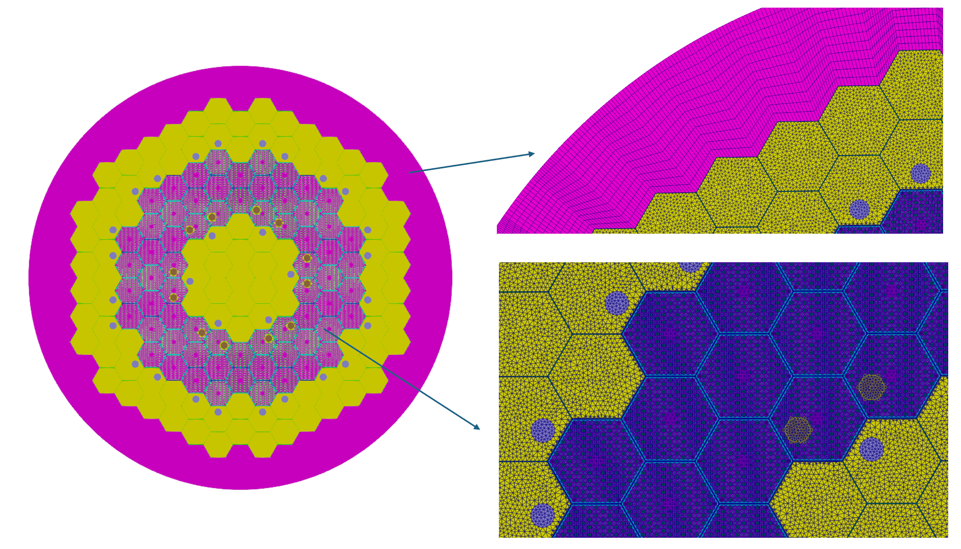
Figure 9: Hexagonal core mesh with ring boundary featuring close ups of ring boundary mesh and core assembly meshes
[Mesh]
  [ring_boundary]
    type = PeripheralRingMeshGenerator
    input = delete_assemblies
    peripheral_layer_num = 12
    peripheral_ring_radius = ${outer_core_ring_radius}
    input_mesh_external_boundary = radial_edge_boundary
    peripheral_ring_block_id = ${graphite_quad_block_id}
    peripheral_ring_block_name = ${graphite_quad_block_name}
    external_boundary_id = 3
    external_boundary_name = ring_edge_boundary
  []
[]The mesh is extruded with 4 graphite axial layers for the bottom reflector, 10 fuel axial layers in the center for the core and 1 axial graphite layer for the top reflector to create a 3D mesh.
[Mesh]
  [extrude]
    type = AdvancedExtruderGenerator
    input = ring_boundary
    direction = '0 0 1'
    bottom_boundary = '1'
    top_boundary = '2'
    # 4 Graphite Layers, 10 Fuel Layers, 1 Graphite Layer
    #heights =    '59.47 39.65 39.65 59.48 79.30 79.30 79.29 79.30 79.30 79.30 79.30 79.30 79.30 79.30 118.94'
    #num_layers =     '1     1     1     1     1     1     1     1     1     1     1     1     1     1      1'
    heights = '198.25 792.99 118.94'
    # num_layers = '20 80 12'
    num_layers = '1 1 1'
    subdomain_swaps = '
    ${fuel_quad_block_id}             ${graphite_quad_block_id}
    ${burnable_poison_quad_block_id}  ${graphite_quad_block_id}
    ${cr_hole_tri_block_id}           ${graphite_tri_block_id}
    ${rsc_hole_tri_block_id}          ${graphite_tri_block_id};
    ;
    ${fuel_quad_block_id}             ${graphite_quad_block_id}
    ${burnable_poison_quad_block_id}  ${graphite_quad_block_id}
    ${cr_hole_tri_block_id}           ${graphite_tri_block_id}
    ${rsc_hole_tri_block_id}          ${graphite_tri_block_id}
    '
  []
[]The blocks are renamed for convenience, and then element and depletion ids are assigned.
[Mesh]
  [add_plane_id]
    type = PlaneIDMeshGenerator
    input = extrude
    plane_coordinates = '0.00 198.25 991.24 1110.18'
    # num_ids_per_plane = '20 80 12'
    num_ids_per_plane = '1 1 1'
    plane_axis = 'z'
    id_name = plane_id
  []
[][Mesh]
[rename_blocks]
type = RenameBlockGenerator
input = add_plane_id
old_block = '${fuel_quad_block_id} ${burnable_poison_quad_block_id} ${helium_quad_block_id} ${graphite_tri_block_id} ${graphite_quad_block_id} ${cr_hole_tri_block_id} ${rsc_hole_tri_block_id} ${assembly_graphite_quad_block_id} ${assembly_helium_quad_block_id}'
new_block = '${fuel_quad_block_name} ${burnable_poison_quad_block_name} ${helium_quad_block_name} ${graphite_tri_block_name} ${graphite_quad_block_name} ${cr_hole_tri_block_name} ${rsc_hole_tri_block_name} ${assembly_graphite_quad_block_name} ${assembly_helium_quad_block_id}'
[]
[][Mesh]
[add_material_id]
type = ExtraElementIDCopyGenerator
input = rename_blocks
source_extra_element_id = subdomain_id
target_extra_element_ids = 'material_id'
[]
[][Mesh]
[add_depletion_id]
type = DepletionIDGenerator
input = 'add_material_id'
id_name = 'assembly_id pin_id plane_id'
material_id_name = 'material_id'
[]
[]Coarse Mesh Overlay Definition
Lastly the coarse mesh hexagon is generated with the same dimensions as the fine mesh.
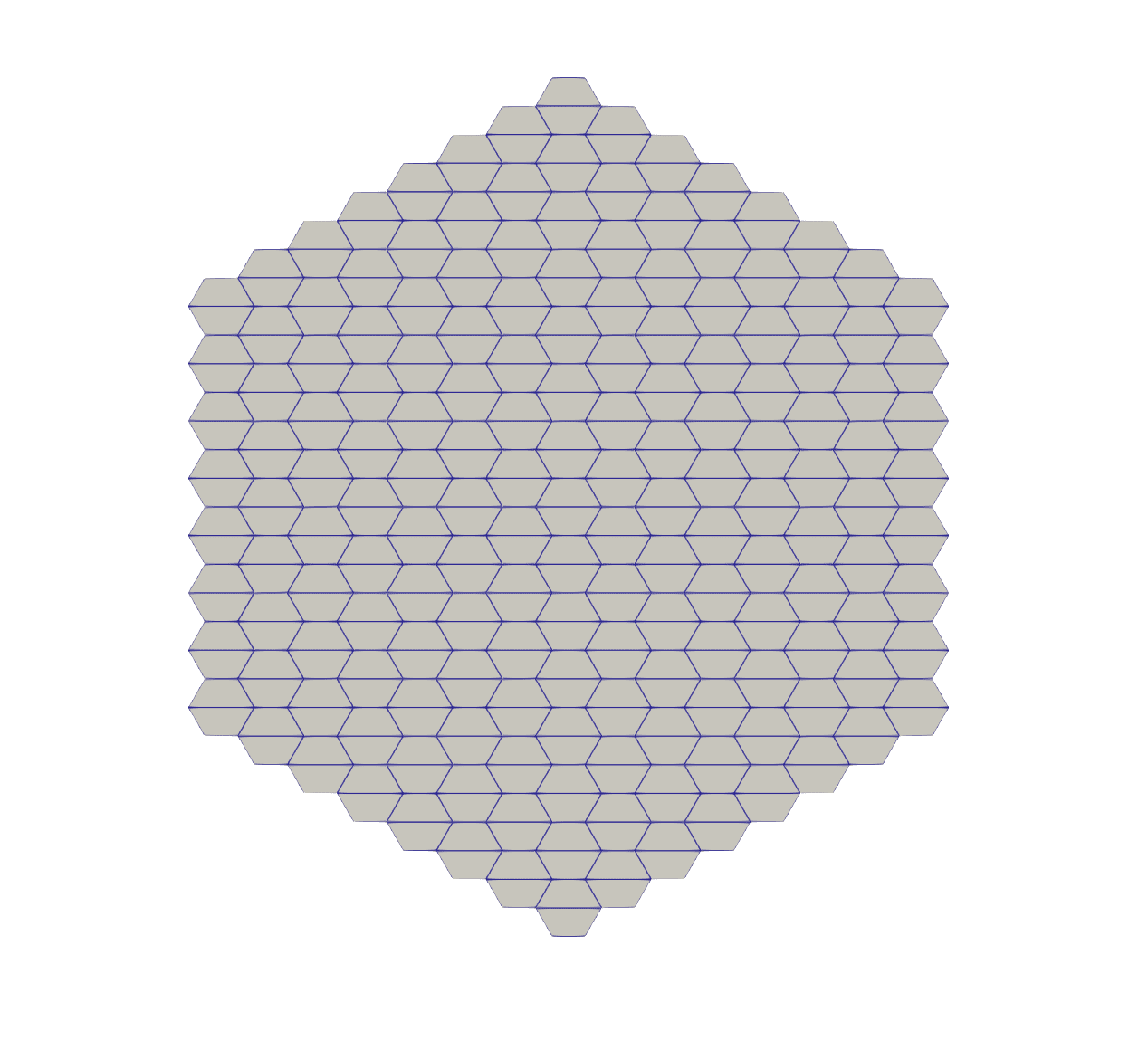
Figure 11: Coarse hexagonal core mesh
[Mesh]
  [coarse_mesh_hex]
    type = SimpleHexagonGenerator
    element_type = QUAD
    hexagon_size = ${assembly_apothem}
    block_id = 100
    block_name = coarse_hexagon
  []
[][Mesh]
[coarse_mesh_hex_meta]
type = AddMetaDataGenerator
input = coarse_mesh_hex
[]
[][Mesh]
[coarse_hex_core]
type = PatternedHexMeshGenerator
inputs = 'coarse_mesh_hex_meta'
pattern = '
00 00 00 00 00 00 00 00;
00 00 00 00 00 00 00 00 00;
00 00 00 00 00 00 00 00 00 00;
00 00 00 00 00 00 00 00 00 00 00;
00 00 00 00 00 00 00 00 00 00 00 00;
00 00 00 00 00 00 00 00 00 00 00 00 00;
00 00 00 00 00 00 00 00 00 00 00 00 00 00;
00 00 00 00 00 00 00 00 00 00 00 00 00 00 00;
00 00 00 00 00 00 00 00 00 00 00 00 00 00;
00 00 00 00 00 00 00 00 00 00 00 00 00;
00 00 00 00 00 00 00 00 00 00 00 00;
00 00 00 00 00 00 00 00 00 00 00;
00 00 00 00 00 00 00 00 00 00;
00 00 00 00 00 00 00 00 00;
00 00 00 00 00 00 00 00'
id_name = coarse_assembly_id
assign_type = cell
pattern_boundary = none
external_boundary_id = 330
external_boundary_name = 'coarse_radial_edge_boundary'
generate_core_metadata = true
[]
[]The metadata is added to the coarse mesh, another ring boundary is created, and the 2D coarse mesh is then extruded.
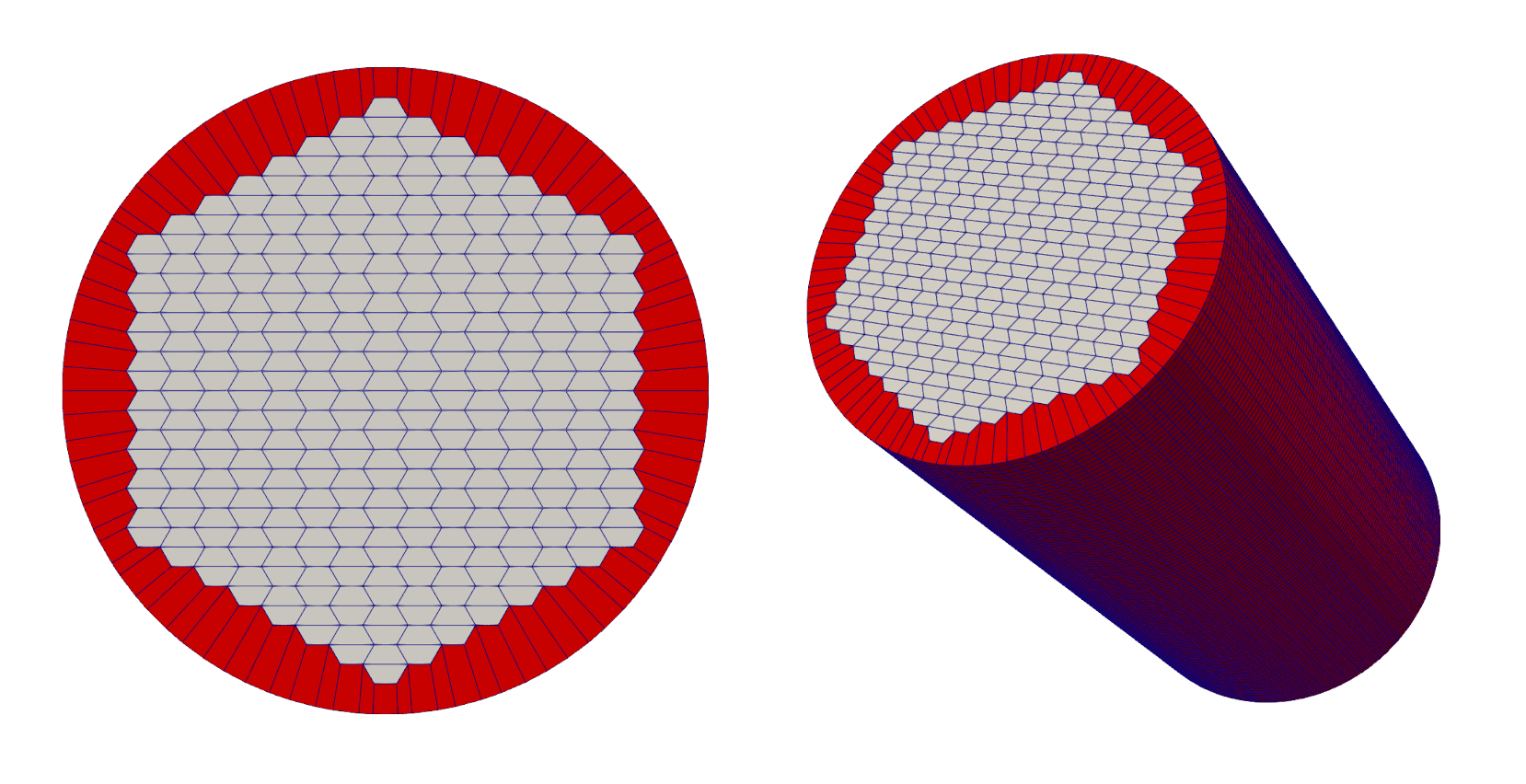
Figure 12: Left: Coarse hexagonal core mesh with ring boundary; Right: 3D, Extruded coarse hexagonal core mesh
[Mesh]
  [coarse_ring]
    type = PeripheralRingMeshGenerator
    input = coarse_hex_core
    peripheral_layer_num = 1
    peripheral_ring_radius = '${fparse outer_core_ring_radius + 1.0}'
    input_mesh_external_boundary = coarse_radial_edge_boundary
    peripheral_ring_block_id = 1001
    peripheral_ring_block_name = coarse_assembly_ring
    external_boundary_id = 13
    external_boundary_name = coarse_ring_edge_boundary
  []
[][Mesh]
[coarse_extrude]
type = AdvancedExtruderGenerator
input = coarse_ring
direction = '0 0 1'
bottom_boundary = '1'
top_boundary = '2'
heights = '198.25 792.99 118.94'
num_layers = '20 80 12'
[]
[]Finally the coarse mesh is superimposed onto the fine mesh. The coarse mesh is used for Coarse Mesh Finite Difference, a transport acceleration technique. This results in the final 3D MHTGR hexagonal core mesh.
[Mesh]
  [coarse_mesh_id]
    type = CoarseMeshExtraElementIDGenerator
    input = add_depletion_id
    coarse_mesh = coarse_extrude
    extra_element_id_name = coarse_element_id
  []
[]This method is used when solving full-core analysis in the Nuclear Energy Advanced Modeling and Simulation (NEAMS) code Griffin. More information regarding Griffin is available here.
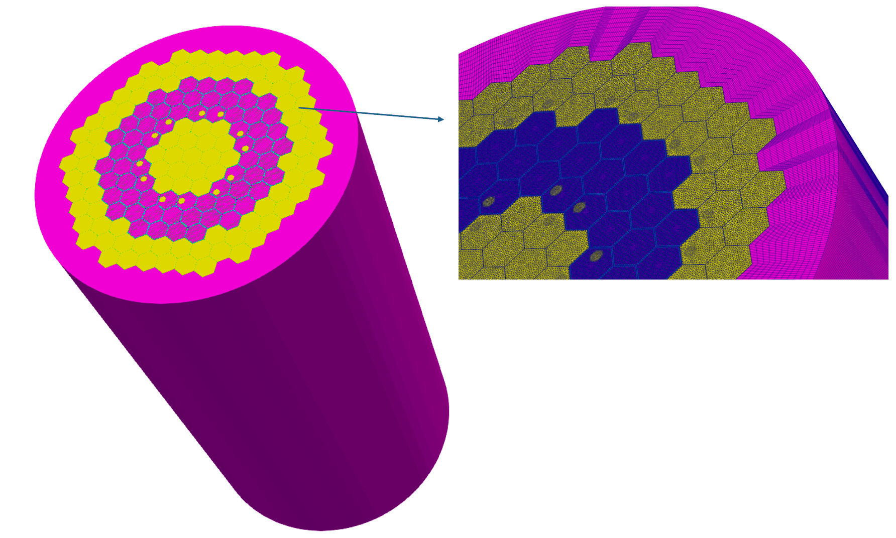
Figure 13: 3D MHTGR Hexagonal core mesh featuring close ups of core assembly meshes and ring barrier mesh
(htgr/mhtgr/3D_mesh/3D_mhtgr_final.i)
# ###########################################################################
# Created by: Olin Calvin (INL), Javier Ortensi (INL), and Yeon Sang Jung (ANL)
# Start Date: Unknown
# Revision Date: Aug 28, 2023
# Version Number: 6
# Project: MHTGR
# Description: 3D MHTGR trying to debug mesh hanging with coarse mesh
# Input units: cm
# Mesh units: cm
# ###########################################################################
# constant_names = 'pi'
# constant_expressions = '${fparse pi}'
xydg_reflector_assembly_desired_area = 2.5
xydg_rsc_hole_desired_area = 1.0
xydg_cr_hole_desired_area = 1.5
cr_hole_num_segments = 18
rsc_hole_num_segments = 24
# Includes duct
assembly_apothem = 18.0
assembly_pitch = '${fparse 2.0*assembly_apothem}'
duct_thickness = 0.2
duct_apothem = '${fparse assembly_apothem - duct_thickness}'
# Number of sides for pin cell polygons
pin_num_sides = 6
pin_num_sectors_per_side = 2
pin_num_sectors_per_side_vector = '${pin_num_sectors_per_side} ${pin_num_sectors_per_side} ${pin_num_sectors_per_side} ${pin_num_sectors_per_side} ${pin_num_sectors_per_side} ${pin_num_sectors_per_side}'
pin_cell_apothem = 0.9398
# From Table I.3 from the MHTGR Report
#burnable_poison_radius = 0.5715
burnable_poison_gap_radius = 0.635
# We will smear the He gap and burnable poison for now
#burnable_poison_area = '${fparse pi * burnable_poison_gap_radius * burnable_poison_gap_radius}'
#burnable_poison_apothem = '${fparse sqrt(burnable_poison_area / (2 * sqrt(3)))}'
# From Table I.4 from the MHTGR report
#fuel_radius = 0.6225
fuel_gap_radius = 0.635
# We will smear the He gap and fuel for now
#fuel_area = '${fparse pi * fuel_gap_radius * fuel_gap_radius}'
# If we decide to use a simple hex, we want to choose an apothem that preserves total area
#fuel_gap_apothem = '${fparse sqrt(fuel_area / (2 * sqrt(3)))}'
# From Table I.3 from the MHTGR Report
large_coolant_radius = 0.794
#large_coolant_area = '${fparse pi * large_coolant_radius * large_coolant_radius}'
#large_coolant_apothem = '${fparse sqrt(large_coolant_area / (2 * sqrt(3)))}'
# From Table I.3 from the MHTGR Report
small_coolant_radius = 0.635
#small_coolant_area = '${fparse pi * small_coolant_radius * small_coolant_radius}'
#small_coolant_apothem = '${fparse sqrt(small_coolant_area / (2 * sqrt(3)))}'
rsc_hole_radius = 4.7625
rsc_hole_xpos = -4.878
rsc_hole_ypos = 8.449
cr_hole_radius = 5.1
cr_hole_xpos = 4.878
cr_hole_ypos = 8.449
# Have to adapt non-fuel assemblies to the fuel assemblies.
# Have to get this number by opening the fuel assembly mesh in Paraview and viewing it.
num_fuel_assembly_sectors = 32
# Number of sectors on the sides of non-fuel assemblies which DO NOT border fuel assemblies
num_non_fuel_assembly_sectors = 12
outer_core_ring_radius = 297.3
# Block IDs/Names
#fuel_tri_block_id = 10
#fuel_tri_block_name = fuel_tri
fuel_quad_block_id = 11
fuel_quad_block_name = fuel_quad
#burnable_poison_tri_block_id = 20
#burnable_poison_tri_block_name = burnable_poison_tri
burnable_poison_quad_block_id = 21
burnable_poison_quad_block_name = burnable_poison_quad
#helium_tri_block_id = 30
#helium_tri_block_name = helium_tri
helium_quad_block_id = 31
helium_quad_block_name = helium_quad
#assembly_helium_tri_block_id = 32
#assembly_helium_tri_block_name = assembly_helium_tri
assembly_helium_quad_block_id = 33
assembly_helium_quad_block_name = assembly_helium_quad
graphite_tri_block_id = 40
graphite_tri_block_name = graphite_tri
graphite_quad_block_id = 41
graphite_quad_block_name = graphite_quad
# Need separate IDs for the graphite in the assembly background
# Otherwise pin_id assignement fails
#assembly_graphite_tri_block_id = 42
#assembly_graphite_tri_block_name = assembly_graphite_tri
assembly_graphite_quad_block_id = 43
assembly_graphite_quad_block_name = assembly_graphite_quad
cr_hole_tri_block_id = 50
cr_hole_tri_block_name = cr_hole_tri
#cr_hole_quad_block_id = 51
#cr_hole_quad_block_name = cr_hole_quad
rsc_hole_tri_block_id = 60
rsc_hole_tri_block_name = rsc_hole_tri
#rsc_hole_quad_block_id = 61
#rsc_hole_quad_block_name = rsc_hole_quad
# Create special block ID for deletion
# If we see this name in the final mesh then a mistake was made somewhere
to_delete_block_id = 100
to_delete_block_name = to_delete
# We sometimes need a temporary block ID, so we have this
temp_block_id = 101
temp_block_name = temp_block
# Special boundary IDs counting up from 100
# Helps avoid using random numbers
# boundary_01_id = 101
# boundary_02_id = '${fparse boundary_01_id + 1}'
# boundary_03_id = '${fparse boundary_02_id + 1}'
# boundary_04_id = '${fparse boundary_03_id + 1}'
# boundary_05_id = '${fparse boundary_04_id + 1}'
#boundary_06_id = '${fparse boundary_05_id + 1}'
#boundary_07_id = '${fparse boundary_06_id + 1}'
#boundary_08_id = '${fparse boundary_07_id + 1}'
#boundary_09_id = '${fparse boundary_08_id + 1}'
fuel_assembly_boundary_id = 200
fuel_assembly_boundary_name = fuel_assembly_boundary
[GlobalParams]
# Prevents extra debugging info from being shown.
# Even with this set to false there is a lot printed to console
show_info = false
# Define pi which will be used frequently when carving holes in meshes
# These metadata values are required by PatternedHexMeshGenerator
# These values are used by the AddMetaDataGenerator
real_scalar_metadata_names = 'pitch_meta pattern_pitch_meta'
# Pitch of the hexagonal fuel assembly including duct around assembly
real_scalar_metadata_values = '${assembly_pitch} ${assembly_pitch}'
boolean_scalar_metadata_names = 'is_control_drum_meta'
boolean_scalar_metadata_values = 'false'
# apothem of pin cell (half the pitch of the pin cell)
polygon_size = ${pin_cell_apothem}
polygon_size_style = apothem
[]
[Mesh]
# Describes the burnable poison pin geometry
[burnable_poison_pin_mesh]
type = PolygonConcentricCircleMeshGenerator
# Define cell as hexagon
num_sides = ${pin_num_sides}
# Define number of elements on each side for the azimuthal discretization
# This must be an even number
num_sectors_per_side = ${pin_num_sectors_per_side_vector}
# Define the block ID and name of the background block ID
# The background block ID describes the area of the polygon outside of the rings
background_block_ids = '${graphite_quad_block_id}'
background_block_names = '${graphite_quad_block_name}'
# Defines the number of ring blocks (based on the length of ring_intervals) and the number of spatial ring refinement for each of the ring blocks
ring_intervals = '1'
# First value describes the outer radius of the innermost ring and the inner radius of the next ring
ring_radii = '${burnable_poison_gap_radius}'
ring_block_ids = '${burnable_poison_quad_block_id}'
ring_block_names = '${burnable_poison_quad_block_name}'
# By using quad center elements we avoid having lots of element boundaries intersecting in the center of the pin.
# Additionally, TRI and QUAD elements are not allowed to have the same block ID, so this allows us to have more of the same block IDs
quad_center_elements = true
create_inward_interface_boundaries = false
create_outward_interface_boundaries = false
[]
# Describes the fuel pin geometry
[fuel_pin_mesh]
type = PolygonConcentricCircleMeshGenerator
num_sides = ${pin_num_sides}
num_sectors_per_side = ${pin_num_sectors_per_side_vector}
background_block_ids = '${graphite_quad_block_id}'
background_block_names = '${graphite_quad_block_name}'
ring_intervals = '1'
ring_radii = '${fuel_gap_radius}'
ring_block_ids = '${fuel_quad_block_id}'
ring_block_names = '${fuel_quad_block_name}'
quad_center_elements = true
create_inward_interface_boundaries = false
create_outward_interface_boundaries = false
[]
# Describes the large coolant channel geometry
[large_coolant_channel_mesh]
type = PolygonConcentricCircleMeshGenerator
num_sides = ${pin_num_sides}
num_sectors_per_side = ${pin_num_sectors_per_side_vector}
background_block_ids = '${graphite_quad_block_id}'
background_block_names = '${graphite_quad_block_name}'
ring_intervals = '1'
ring_radii = '${large_coolant_radius}'
ring_block_ids = '${helium_quad_block_id}'
ring_block_names = '${helium_quad_block_name}'
quad_center_elements = true
create_inward_interface_boundaries = false
create_outward_interface_boundaries = false
[]
# Describes the small coolant channel geometry
[small_coolant_channel_mesh]
type = PolygonConcentricCircleMeshGenerator
num_sides = ${pin_num_sides}
num_sectors_per_side = ${pin_num_sectors_per_side_vector}
background_block_ids = '${graphite_quad_block_id}'
background_block_names = '${graphite_quad_block_name}'
ring_intervals = '1'
ring_radii = '${small_coolant_radius}'
ring_block_ids = '${helium_quad_block_id}'
ring_block_names = '${helium_quad_block_name}'
quad_center_elements = true
create_inward_interface_boundaries = false
create_outward_interface_boundaries = false
[]
# Describes the empty pin (i.e. reflector only hexagonal unit cell)
[empty_pin]
type = PolygonConcentricCircleMeshGenerator
num_sides = ${pin_num_sides}
num_sectors_per_side = ${pin_num_sectors_per_side_vector}
background_block_ids = '${graphite_quad_block_id}'
background_block_names = '${graphite_quad_block_name}'
quad_center_elements = true
create_inward_interface_boundaries = false
create_outward_interface_boundaries = false
[]
# Describes the empty pin (i.e. reflector only hexagonal unit cell) which will be deleted from the mesh which will have the RSC hole
# We need to define a new block ID so that we only delete the specific block of interest
[empty_pin_to_delete]
type = PolygonConcentricCircleMeshGenerator
num_sides = ${pin_num_sides}
num_sectors_per_side = ${pin_num_sectors_per_side_vector}
background_block_ids = '${to_delete_block_id}'
background_block_names = '${to_delete_block_name}'
quad_center_elements = true
create_inward_interface_boundaries = false
create_outward_interface_boundaries = false
[]
# Hexagonal fuel assembly with no RSC
[fuel_assembly]
type = PatternedHexMeshGenerator
# 0 burnable_poison_pin_mesh
# 1 fuel_pin_mesh
# 2 large_coolant_channel_mesh
# 3 empty_pin
# 4 small_coolant_channel_mesh
inputs = 'burnable_poison_pin_mesh fuel_pin_mesh large_coolant_channel_mesh empty_pin small_coolant_channel_mesh'
pattern = '
0 1 2 1 1 2 1 1 2 1 0;
1 2 1 1 2 1 1 2 1 1 2 1;
2 1 1 2 1 1 2 1 1 2 1 1 2;
1 1 2 1 1 2 1 1 2 1 1 2 1 1;
1 2 1 1 2 1 1 2 1 1 2 1 1 2 1;
2 1 1 2 1 1 2 1 1 2 1 1 2 1 1 2;
1 1 2 1 1 2 1 1 2 1 1 2 1 1 2 1 1;
1 2 1 1 2 1 1 2 1 1 2 1 1 2 1 1 2 1;
2 1 1 2 1 1 2 1 1 4 1 1 2 1 1 2 1 1 2;
1 1 2 1 1 2 1 1 4 3 3 4 1 1 2 1 1 2 1 1;
0 2 1 1 2 1 1 2 1 3 3 3 1 2 1 1 2 1 1 2 0;
1 1 2 1 1 2 1 1 4 3 3 4 1 1 2 1 1 2 1 1;
2 1 1 2 1 1 2 1 1 4 1 1 2 1 1 2 1 1 2;
1 2 1 1 2 1 1 2 1 1 2 1 1 2 1 1 2 1;
1 1 2 1 1 2 1 1 2 1 1 2 1 1 2 1 1;
2 1 1 2 1 1 2 1 1 2 1 1 2 1 1 2;
1 2 1 1 2 1 1 2 1 1 2 1 1 2 1;
1 1 2 1 1 2 1 1 2 1 1 2 1 1;
2 1 1 2 1 1 2 1 1 2 1 1 2;
1 2 1 1 2 1 1 2 1 1 2 1;
0 1 2 1 1 2 1 1 2 1 0'
id_name = pin_id
assign_type = cell
pattern_boundary = hexagon
hexagon_size = ${assembly_apothem}
duct_sizes = ${duct_apothem}
duct_intervals = 1
duct_block_ids = '${assembly_helium_quad_block_id}'
duct_block_names = '${assembly_helium_quad_block_name}'
background_block_id = ${assembly_graphite_quad_block_id}
background_block_name = ${assembly_graphite_quad_block_name}
external_boundary_id = ${fuel_assembly_boundary_id}
external_boundary_name = ${fuel_assembly_boundary_name}
generate_core_metadata = true
background_intervals = 1
[]
# Hexagonal fuel assembly with RSC
[fuel_assembly_with_rsc]
type = PatternedHexMeshGenerator
# 0 burnable_poison_pin_mesh
# 1 fuel_pin_mesh
# 2 large_coolant_channel_mesh
# 3 empty_pin
# 4 empty_pin_to_delete
# 5 small_coolant_channel_mesh
inputs = 'burnable_poison_pin_mesh fuel_pin_mesh large_coolant_channel_mesh empty_pin empty_pin_to_delete small_coolant_channel_mesh'
pattern = '
0 1 2 1 1 2 1 1 2 1 0;
1 2 1 1 2 1 1 2 1 1 2 1;
2 1 1 2 1 1 2 1 1 2 1 1 2;
1 1 2 1 1 2 1 1 2 1 1 2 1 1;
1 2 1 1 2 1 1 2 1 1 4 4 4 4 1;
2 1 1 2 1 1 2 1 1 2 4 4 4 4 4 2;
1 1 2 1 1 2 1 1 2 1 4 4 4 4 4 4 1;
1 2 1 1 2 1 1 2 1 1 4 4 4 4 4 4 4 1;
2 1 1 2 1 1 2 1 1 5 1 4 4 4 4 4 4 1 2;
1 1 2 1 1 2 1 1 5 3 3 5 4 4 4 4 4 2 1 1;
0 2 1 1 2 1 1 2 1 3 3 3 1 4 4 4 4 1 1 2 0;
1 1 2 1 1 2 1 1 5 3 3 5 1 1 2 1 1 2 1 1;
2 1 1 2 1 1 2 1 1 5 1 1 2 1 1 2 1 1 2;
1 2 1 1 2 1 1 2 1 1 2 1 1 2 1 1 2 1;
1 1 2 1 1 2 1 1 2 1 1 2 1 1 2 1 1;
2 1 1 2 1 1 2 1 1 2 1 1 2 1 1 2;
1 2 1 1 2 1 1 2 1 1 2 1 1 2 1;
1 1 2 1 1 2 1 1 2 1 1 2 1 1;
2 1 1 2 1 1 2 1 1 2 1 1 2;
1 2 1 1 2 1 1 2 1 1 2 1;
0 1 2 1 1 2 1 1 2 1 0'
id_name = pin_id
assign_type = cell
pattern_boundary = hexagon
hexagon_size = ${assembly_apothem}
duct_sizes = ${duct_apothem}
duct_intervals = 1
duct_block_ids = '${assembly_helium_quad_block_id}'
duct_block_names = '${assembly_helium_quad_block_name}'
background_block_id = ${assembly_graphite_quad_block_id}
background_block_name = ${assembly_graphite_quad_block_name}
external_boundary_id = ${fuel_assembly_boundary_id}
external_boundary_name = ${fuel_assembly_boundary_name}
generate_core_metadata = true
background_intervals = 1
[]
# Delete the "pin cells" from the fuel_assembly_with_rsc mesh to carve the hole for the RSC
[delete_pins_for_rsc]
type = BlockDeletionGenerator
input = fuel_assembly_with_rsc
block = '${to_delete_block_name}'
new_boundary = 'rsc_area_assembly_boundary'
[]
# The deletion has created a void where the deleted pin cells were. We now assign a block ID to the deleted area
[rebuild_rsc_void]
type = LowerDBlockFromSidesetGenerator
input = delete_pins_for_rsc
sidesets = 'rsc_area_assembly_boundary'
new_block_id = ${temp_block_id}
new_block_name = ${temp_block_name}
[]
# Next we mesh the area with the new block ID, removing the void
[convert_rsc_void_to_mesh]
type = BlockToMeshConverterGenerator
input = rebuild_rsc_void
target_blocks = ${temp_block_name}
[]
# Now ParsedCurveGenerator can be used to generate the boundary of the RSC hole
# Diameter of 9.525 cm specified in Table 3
# Center of hole distance of 3.841 in (9.756 cm)
[rsc_hole]
type = ParsedCurveGenerator
x_formula = '${rsc_hole_radius}*cos(t) + ${rsc_hole_xpos}'
y_formula = '${rsc_hole_radius}*sin(t) + ${rsc_hole_ypos}'
section_bounding_t_values = '0.0 ${fparse 2.0*pi}'
nums_segments = '${rsc_hole_num_segments}'
is_closed_loop = true
[]
# Next we use XYDelaunayGenerator (XYDG) to carve the hole in the area of the pin cells we designated for the RSC hole
[rsc_area_with_hole]
type = XYDelaunayGenerator
boundary = 'convert_rsc_void_to_mesh'
holes = 'rsc_hole'
hole_boundaries = 'heterogeneous_hole_boundary'
add_nodes_per_boundary_segment = 0
output_boundary = 10010 # xy_output_boundary
refine_boundary = false
smooth_triangulation = true
desired_area = 0.5
output_subdomain_name = ${graphite_tri_block_id}
[]
# Now that we have the pin cell area with the RSC hole carved in it
# we now stitch this pin cell area back into the fuel assembly
# which the pin cell area was deleted from.
# Note that the RSC hole carved is currently unmeshed (i.e. void)
[fuel_assembly_with_rsc_hole_void]
type = StitchedMeshGenerator
inputs = 'delete_pins_for_rsc rsc_area_with_hole'
stitch_boundaries_pairs = 'rsc_area_assembly_boundary 10010'
[]
# Since we want the RSC hole meshed we need to get the hole boundary and use XYDG to mesh it
[mesh_rsc_hole_for_fuel_assembly]
type = XYDelaunayGenerator
boundary = 'fuel_assembly_with_rsc_hole_void'
add_nodes_per_boundary_segment = 0
input_boundary_names = heterogeneous_hole_boundary # xy_output_boundary
refine_boundary = false
smooth_triangulation = true
output_subdomain_name = ${rsc_hole_tri_block_id}
output_boundary = to_stitch_third
desired_area = ${xydg_rsc_hole_desired_area}
[]
# Now we must stitch the meshed RSC hole to the fuel assembly with the RSC void
[fuel_assembly_w_rsc_stitched]
type = StitchedMeshGenerator
inputs = 'fuel_assembly_with_rsc_hole_void mesh_rsc_hole_for_fuel_assembly'
stitch_boundaries_pairs = 'heterogeneous_hole_boundary to_stitch_third'
[]
# Lastly, since we are using the PatternedHexMeshGenerator additional metadata is needed in order for pattern mesh generator to accept the given mesh
# We will need to do this frequently, so the metadata values are defined in GlobalParams
# And are the same for all AddMetaDataGenerators used
# We refer to it as "fuel_assembly_with_rsc_1" in order to refer to the index of the hexagon side the RSC is next to
[fuel_assembly_with_rsc_1]
type = AddMetaDataGenerator
input = fuel_assembly_w_rsc_stitched
[]
# Because the RSC is oriented in 6 different positions, we need to generate all 6 rotated variations of the assembly.
# We have already generated 1 so far, so now we need to use rotational transformations in order to generate the other 5
# Since transformations will strip any metadata from the input mesh, we can use the stitched mesh, rotate it, then add the metadata
# We title the transformations based on the side of the assembly the RSC is on.
# Side indices can be found at https://mooseframework.inl.gov/source/meshgenerators/PolygonConcentricCircleMeshGenerator.html
# Fuel Assembly w/RSC Hole Side 0
[transform_fuel_assembly_w_rsc_0]
type = TransformGenerator
input = fuel_assembly_w_rsc_stitched
transform = ROTATE
vector_value = '-60 0 0'
[]
[fuel_assembly_w_rsc_0]
type = AddMetaDataGenerator
input = transform_fuel_assembly_w_rsc_0
[]
# Fuel Assembly w/RSC Hole Side 2
[transform_fuel_assembly_w_rsc_2]
type = TransformGenerator
input = fuel_assembly_w_rsc_stitched
transform = ROTATE
vector_value = '60 0 0'
[]
[fuel_assembly_w_rsc_2]
type = AddMetaDataGenerator
input = transform_fuel_assembly_w_rsc_2
[]
# Fuel Assembly w/RSC Hole Side 3
[transform_fuel_assembly_w_rsc_3]
type = TransformGenerator
input = fuel_assembly_w_rsc_stitched
transform = ROTATE
vector_value = '120 0 0'
[]
[fuel_assembly_w_rsc_3]
type = AddMetaDataGenerator
input = transform_fuel_assembly_w_rsc_3
[]
# Fuel Assembly w/RSC Hole Side 4
[transform_fuel_assembly_w_rsc_4]
type = TransformGenerator
input = fuel_assembly_w_rsc_stitched
transform = ROTATE
vector_value = '180 0 0'
[]
[fuel_assembly_w_rsc_4]
type = AddMetaDataGenerator
input = transform_fuel_assembly_w_rsc_4
[]
# Fuel Assembly w/RSC Hole Side 5
[transform_fuel_assembly_w_rsc_5]
type = TransformGenerator
input = fuel_assembly_w_rsc_stitched
transform = ROTATE
vector_value = '-120 0 0'
[]
[fuel_assembly_w_rsc_5]
type = AddMetaDataGenerator
input = transform_fuel_assembly_w_rsc_5
[]
# Reflector assemblies can share the same block ID and block names since they are made of the same material
# We first declare the overall geometry of the reflector assemblies which includes the duct
# However, we will delete the interior of the reflector assembly later in order to avoid
# having long, thin elements which all intersect in the center of the hexagon
[reflector_assembly_base]
type = HexagonConcentricCircleAdaptiveBoundaryMeshGenerator
hexagon_size_style = apothem
hexagon_size = ${assembly_apothem}
duct_sizes = ${duct_apothem}
duct_sizes_style = apothem
duct_intervals = 1
background_block_ids = '${to_delete_block_id}'
background_block_names = '${to_delete_block_name}'
duct_block_ids = '${helium_quad_block_id}'
duct_block_names = '${helium_quad_block_id}'
num_sectors_per_side = '${num_non_fuel_assembly_sectors} ${num_non_fuel_assembly_sectors} ${num_non_fuel_assembly_sectors} ${num_non_fuel_assembly_sectors} ${num_non_fuel_assembly_sectors} ${num_non_fuel_assembly_sectors}'
[]
# Delete the reflector assembly interior in preparation for re-meshing
[delete_reflector_assembly_interior]
type = BlockDeletionGenerator
input = reflector_assembly_base
block = '${to_delete_block_name}'
new_boundary = 'deleted_reflector_boundary_no_adapt'
[]
# Define a block around the deleted reflector assembly interior
[rebuild_reflector_assembly_interior]
type = LowerDBlockFromSidesetGenerator
input = delete_reflector_assembly_interior
sidesets = 'deleted_reflector_boundary_no_adapt'
new_block_id = ${temp_block_id}
new_block_name = ${temp_block_name}
[]
# Remesh the reflector assembly interior using the newly-defined block
[remesh_reflector_assembly_interior]
type = BlockToMeshConverterGenerator
input = rebuild_reflector_assembly_interior
target_blocks = ${temp_block_name}
[]
# Meshes the reflector assembly interior using triangular elements
[triangulate_reflector_assembly_interior]
type = XYDelaunayGenerator
boundary = 'remesh_reflector_assembly_interior'
add_nodes_per_boundary_segment = 0
output_boundary = 11000 # xy_output_boundary
refine_boundary = false
smooth_triangulation = true
desired_area = ${xydg_reflector_assembly_desired_area}
output_subdomain_name = ${graphite_tri_block_id}
[]
# Stitches the reflector assembly duct back together with the now triangulated reflector assembly interior
[stitch_reflector_assembly]
type = StitchedMeshGenerator
inputs = 'delete_reflector_assembly_interior triangulate_reflector_assembly_interior'
stitch_boundaries_pairs = 'deleted_reflector_boundary_no_adapt 11000'
[]
# Once again we need to add the metadata to the assembly so it can be used by Pattern Mesh Generators
[reflector_assembly]
type = AddMetaDataGenerator
input = stitch_reflector_assembly
[]
# When the reflector assemblies border fuel assemblies, the boundary of the reflector assembly must be adapted such that it can mesh together with the fuel assembly it borders.
# Because of the geometry of MHTGR, we must do this for several different adaptation conditions. Fortunately we can rotate assmeblies with adapted conditions, but this forces us to still repeat the process of generating reflector assemblies several times to accommodate this adaptation.
# Recall that the side indices of polygon mesh generators are numbered from 0 to 5 for hexagons
# Adapt a reflector assembly which borders fuel assemblies on 3 sides
[reflector_assembly_base_0_1_2]
type = HexagonConcentricCircleAdaptiveBoundaryMeshGenerator
hexagon_size_style = apothem
hexagon_size = ${assembly_apothem}
duct_sizes = ${duct_apothem}
duct_sizes_style = apothem
duct_intervals = 1
background_block_ids = '${to_delete_block_id}'
background_block_names = '${to_delete_block_name}'
duct_block_ids = '${helium_quad_block_id}'
duct_block_names = '${helium_quad_block_name}'
sides_to_adapt = '0 1 2'
meshes_to_adapt_to = 'fuel_assembly fuel_assembly fuel_assembly'
num_sectors_per_side = '${num_fuel_assembly_sectors} ${num_fuel_assembly_sectors} ${num_fuel_assembly_sectors} ${num_non_fuel_assembly_sectors} ${num_non_fuel_assembly_sectors} ${num_non_fuel_assembly_sectors}'
[]
[delete_reflector_assembly_interior_0_1_2]
type = BlockDeletionGenerator
input = reflector_assembly_base_0_1_2
block = '${to_delete_block_name}'
new_boundary = 'deleted_reflector_boundary_adapt_0_1_2'
[]
[rebuild_reflector_assembly_interior_0_1_2]
type = LowerDBlockFromSidesetGenerator
input = delete_reflector_assembly_interior_0_1_2
sidesets = 'deleted_reflector_boundary_adapt_0_1_2'
new_block_id = ${temp_block_id}
new_block_name = ${temp_block_name}
[]
[remesh_reflector_assembly_interior_0_1_2]
type = BlockToMeshConverterGenerator
input = rebuild_reflector_assembly_interior_0_1_2
target_blocks = ${temp_block_name}
[]
[triangulate_reflector_assembly_interior_0_1_2]
type = XYDelaunayGenerator
boundary = 'remesh_reflector_assembly_interior_0_1_2'
add_nodes_per_boundary_segment = 0
output_boundary = 11001 # xy_output_boundary
refine_boundary = false
smooth_triangulation = true
desired_area = ${xydg_reflector_assembly_desired_area}
output_subdomain_name = ${graphite_tri_block_id}
[]
[stitch_reflector_assembly_0_1_2]
type = StitchedMeshGenerator
inputs = 'delete_reflector_assembly_interior_0_1_2 triangulate_reflector_assembly_interior_0_1_2'
stitch_boundaries_pairs = 'deleted_reflector_boundary_adapt_0_1_2 11001'
[]
[reflector_assembly_0_1_2]
type = AddMetaDataGenerator
input = stitch_reflector_assembly_0_1_2
[]
# Repeat the transformation process from earlier to get all 6 rotational variations of the adapted reflector assembly
[transform_reflector_assembly_1_2_3]
type = TransformGenerator
input = stitch_reflector_assembly_0_1_2
transform = ROTATE
vector_value = '60 0 0'
[]
[reflector_assembly_1_2_3]
type = AddMetaDataGenerator
input = transform_reflector_assembly_1_2_3
[]
[transform_reflector_assembly_2_3_4]
type = TransformGenerator
input = stitch_reflector_assembly_0_1_2
transform = ROTATE
vector_value = '120 0 0'
[]
[reflector_assembly_2_3_4]
type = AddMetaDataGenerator
input = transform_reflector_assembly_2_3_4
[]
[transform_reflector_assembly_3_4_5]
type = TransformGenerator
input = stitch_reflector_assembly_0_1_2
transform = ROTATE
vector_value = '180 0 0'
[]
[reflector_assembly_3_4_5]
type = AddMetaDataGenerator
input = transform_reflector_assembly_3_4_5
[]
[transform_reflector_assembly_4_5_0]
type = TransformGenerator
input = stitch_reflector_assembly_0_1_2
transform = ROTATE
vector_value = '240 0 0'
[]
[reflector_assembly_4_5_0]
type = AddMetaDataGenerator
input = transform_reflector_assembly_4_5_0
[]
[transform_reflector_assembly_5_0_1]
type = TransformGenerator
input = stitch_reflector_assembly_0_1_2
transform = ROTATE
vector_value = '300 0 0'
[]
[reflector_assembly_5_0_1]
type = AddMetaDataGenerator
input = transform_reflector_assembly_5_0_1
[]
# Now we repeat the above process but for reflector assemblies which border fuel assemblies on 2 sides
[reflector_assembly_base_0_1]
type = HexagonConcentricCircleAdaptiveBoundaryMeshGenerator
hexagon_size_style = apothem
hexagon_size = ${assembly_apothem}
duct_sizes = ${duct_apothem}
duct_sizes_style = apothem
duct_intervals = 1
background_block_ids = '${to_delete_block_id}'
background_block_names = '${to_delete_block_name}'
duct_block_ids = '${helium_quad_block_id}'
duct_block_names = '${helium_quad_block_name}'
sides_to_adapt = '0 1'
meshes_to_adapt_to = 'fuel_assembly fuel_assembly'
num_sectors_per_side = '${num_fuel_assembly_sectors} ${num_fuel_assembly_sectors} ${num_non_fuel_assembly_sectors} ${num_non_fuel_assembly_sectors} ${num_non_fuel_assembly_sectors} ${num_non_fuel_assembly_sectors}'
[]
[delete_reflector_assembly_interior_0_1]
type = BlockDeletionGenerator
input = reflector_assembly_base_0_1
block = '${to_delete_block_name}'
new_boundary = 'deleted_reflector_boundary_adapt_0_1'
[]
[rebuild_reflector_assembly_interior_0_1]
type = LowerDBlockFromSidesetGenerator
input = delete_reflector_assembly_interior_0_1
sidesets = 'deleted_reflector_boundary_adapt_0_1'
new_block_id = ${temp_block_id}
new_block_name = ${temp_block_name}
[]
[remesh_reflector_assembly_interior_0_1]
type = BlockToMeshConverterGenerator
input = rebuild_reflector_assembly_interior_0_1
target_blocks = ${temp_block_name}
[]
[triangulate_reflector_assembly_interior_0_1]
type = XYDelaunayGenerator
boundary = 'remesh_reflector_assembly_interior_0_1'
add_nodes_per_boundary_segment = 0
output_boundary = 11002 # xy_output_boundary
refine_boundary = false
smooth_triangulation = true
desired_area = ${xydg_reflector_assembly_desired_area}
output_subdomain_name = ${graphite_tri_block_id}
[]
[stitch_reflector_assembly_0_1]
type = StitchedMeshGenerator
inputs = 'delete_reflector_assembly_interior_0_1 triangulate_reflector_assembly_interior_0_1'
stitch_boundaries_pairs = 'deleted_reflector_boundary_adapt_0_1 11002'
[]
[reflector_assembly_0_1]
type = AddMetaDataGenerator
input = stitch_reflector_assembly_0_1
[]
# Now we rotate the reflector meshes again to cover all 6 directions
[transform_reflector_assembly_1_2]
type = TransformGenerator
input = stitch_reflector_assembly_0_1
transform = ROTATE
vector_value = '60 0 0'
[]
[reflector_assembly_1_2]
type = AddMetaDataGenerator
input = transform_reflector_assembly_1_2
[]
[transform_reflector_assembly_2_3]
type = TransformGenerator
input = stitch_reflector_assembly_0_1
transform = ROTATE
vector_value = '120 0 0'
[]
[reflector_assembly_2_3]
type = AddMetaDataGenerator
input = transform_reflector_assembly_2_3
[]
[transform_reflector_assembly_3_4]
type = TransformGenerator
input = stitch_reflector_assembly_0_1
transform = ROTATE
vector_value = '180 0 0'
[]
[reflector_assembly_3_4]
type = AddMetaDataGenerator
input = transform_reflector_assembly_3_4
[]
[transform_reflector_assembly_4_5]
type = TransformGenerator
input = stitch_reflector_assembly_0_1
transform = ROTATE
vector_value = '240 0 0'
[]
[reflector_assembly_4_5]
type = AddMetaDataGenerator
input = transform_reflector_assembly_4_5
[]
[transform_reflector_assembly_5_0]
type = TransformGenerator
input = stitch_reflector_assembly_0_1
transform = ROTATE
vector_value = '300 0 0'
[]
[reflector_assembly_5_0]
type = AddMetaDataGenerator
input = transform_reflector_assembly_5_0
[]
# Now we consider the reflector assemblies which have a Control Rod (CR) hole in them and border 2 fuel assemblies
# Once again we will need to cover all 6 directions
[reflector_assembly_w_cr_base_0_1]
type = HexagonConcentricCircleAdaptiveBoundaryMeshGenerator
hexagon_size_style = apothem
hexagon_size = ${assembly_apothem}
duct_sizes = ${duct_apothem}
duct_sizes_style = apothem
duct_intervals = 1
background_block_ids = '${to_delete_block_id}'
background_block_names = '${to_delete_block_name}'
duct_block_ids = '${helium_quad_block_id}'
duct_block_names = '${helium_quad_block_name}'
sides_to_adapt = '0 1'
num_sectors_per_side = '${num_fuel_assembly_sectors} ${num_fuel_assembly_sectors} ${num_non_fuel_assembly_sectors} ${num_non_fuel_assembly_sectors} ${num_non_fuel_assembly_sectors} ${num_non_fuel_assembly_sectors}'
meshes_to_adapt_to = 'fuel_assembly fuel_assembly'
external_boundary_id = 1776
external_boundary_name = hole_mesh_0_1_w_hole_boundary
[]
# Delete the interior of the reflector assembly
[delete_reflector_assembly_interior_w_cr_0_1]
type = BlockDeletionGenerator
input = reflector_assembly_w_cr_base_0_1
block = '${to_delete_block_name}'
new_boundary = '870'
[]
# Assign a block ID to the deleted area
[rebuild_reflector_assembly_interior_w_cr_0_1]
type = LowerDBlockFromSidesetGenerator
input = delete_reflector_assembly_interior_w_cr_0_1
sidesets = '870'
new_block_id = ${temp_block_id}
new_block_name = ${temp_block_name}
[]
# Remesh the block ID of the deleted area
[remesh_reflector_assembly_interior_w_cr_0_1]
type = BlockToMeshConverterGenerator
input = rebuild_reflector_assembly_interior_w_cr_0_1
target_blocks = ${temp_block_name}
[]
# Define the CR hole in the reflector assembly
# Diameter of 10.2 cm specified below Figure 6
# Center of hole is 3.841 inches (9.756 cm) from the center of the assembly
[cr_hole]
type = ParsedCurveGenerator
x_formula = '${cr_hole_radius}*cos(t) + ${cr_hole_xpos}'
y_formula = '${cr_hole_radius}*sin(t) + ${cr_hole_ypos}'
section_bounding_t_values = '0.0 ${fparse 2.0*pi}'
# can increase for better element refinement along the assembly boundary
nums_segments = '${cr_hole_num_segments}'
is_closed_loop = true
[]
# Now we mesh/fill the CR hole in the reflector assembly
[fill_reflector_assembly_cr_hole_0_1]
type = XYDelaunayGenerator
boundary = 'cr_hole'
add_nodes_per_boundary_segment = 0
refine_boundary = false
smooth_triangulation = true
output_subdomain_name = ${cr_hole_tri_block_id}
output_boundary = 871
desired_area = ${xydg_cr_hole_desired_area}
[]
# Triangulate the mesh of the interior reflector assembly except for the CR hole which remains a void
[triangulate_reflector_assembly_w_cr_hole_0_1]
type = XYDelaunayGenerator
boundary = 'remesh_reflector_assembly_interior_w_cr_0_1'
holes = 'fill_reflector_assembly_cr_hole_0_1'
stitch_holes = 'true'
refine_holes = 'false'
add_nodes_per_boundary_segment = 0
output_boundary = 10000 # xy_output_boundary
refine_boundary = false
smooth_triangulation = true
desired_area = ${xydg_reflector_assembly_desired_area}
output_subdomain_name = ${graphite_tri_block_id}
[]
# Stitch the reflector assembly interior with the reflector assembly duct
[stitch_reflector_assembly_cr_hole_filled_0_1]
type = StitchedMeshGenerator
inputs = 'delete_reflector_assembly_interior_w_cr_0_1 triangulate_reflector_assembly_w_cr_hole_0_1'
stitch_boundaries_pairs = '870 10000'
[]
# Now add metadata for Pattern Mesh Generator
[reflector_assembly_w_cr_hole_0_1]
type = AddMetaDataGenerator
input = stitch_reflector_assembly_cr_hole_filled_0_1
[]
# Some of the assemblies are reflected so we actually need 12 permutations
[transform_reflector_assembly_w_cr_hole_0_1_reflected]
type = TransformGenerator
input = stitch_reflector_assembly_cr_hole_filled_0_1
transform = ROTATE
vector_value = '180 180 0'
[]
[reflector_assembly_w_cr_hole_0_1_reflected]
type = AddMetaDataGenerator
input = transform_reflector_assembly_w_cr_hole_0_1_reflected
[]
[transform_reflector_assembly_w_cr_hole_5_0_reflected]
type = TransformGenerator
input = transform_reflector_assembly_w_cr_hole_0_1_reflected
transform = ROTATE
vector_value = '-60 0 0'
[]
[reflector_assembly_w_cr_hole_5_0_reflected]
type = AddMetaDataGenerator
input = transform_reflector_assembly_w_cr_hole_5_0_reflected
[]
[transform_reflector_assembly_w_cr_hole_4_5_reflected]
type = TransformGenerator
input = transform_reflector_assembly_w_cr_hole_0_1_reflected
transform = ROTATE
vector_value = '-120 0 0'
[]
[reflector_assembly_w_cr_hole_4_5_reflected]
type = AddMetaDataGenerator
input = transform_reflector_assembly_w_cr_hole_4_5_reflected
[]
[transform_reflector_assembly_w_cr_hole_3_4_reflected]
type = TransformGenerator
input = transform_reflector_assembly_w_cr_hole_0_1_reflected
transform = ROTATE
vector_value = '180 0 0'
[]
[reflector_assembly_w_cr_hole_3_4_reflected]
type = AddMetaDataGenerator
input = transform_reflector_assembly_w_cr_hole_3_4_reflected
[]
[transform_reflector_assembly_w_cr_hole_2_3_reflected]
type = TransformGenerator
input = transform_reflector_assembly_w_cr_hole_0_1_reflected
transform = ROTATE
vector_value = '120 0 0'
[]
[reflector_assembly_w_cr_hole_2_3_reflected]
type = AddMetaDataGenerator
input = transform_reflector_assembly_w_cr_hole_2_3_reflected
[]
[transform_reflector_assembly_w_cr_hole_1_2_reflected]
type = TransformGenerator
input = transform_reflector_assembly_w_cr_hole_0_1_reflected
transform = ROTATE
vector_value = '60 0 0'
[]
[reflector_assembly_w_cr_hole_1_2_reflected]
type = AddMetaDataGenerator
input = transform_reflector_assembly_w_cr_hole_1_2_reflected
[]
[transform_reflector_assembly_w_cr_hole_5_0]
type = TransformGenerator
input = stitch_reflector_assembly_cr_hole_filled_0_1
transform = ROTATE
vector_value = '-60 0 0'
[]
[reflector_assembly_w_cr_hole_5_0]
type = AddMetaDataGenerator
input = transform_reflector_assembly_w_cr_hole_5_0
[]
[transform_reflector_assembly_w_cr_hole_4_5]
type = TransformGenerator
input = stitch_reflector_assembly_cr_hole_filled_0_1
transform = ROTATE
vector_value = '-120 0 0'
[]
[reflector_assembly_w_cr_hole_4_5]
type = AddMetaDataGenerator
input = transform_reflector_assembly_w_cr_hole_4_5
[]
[transform_reflector_assembly_w_cr_hole_3_4]
type = TransformGenerator
input = stitch_reflector_assembly_cr_hole_filled_0_1
transform = ROTATE
vector_value = '180 0 0'
[]
[reflector_assembly_w_cr_hole_3_4]
type = AddMetaDataGenerator
input = transform_reflector_assembly_w_cr_hole_3_4
[]
[transform_reflector_assembly_w_cr_hole_2_3]
type = TransformGenerator
input = stitch_reflector_assembly_cr_hole_filled_0_1
transform = ROTATE
vector_value = '120 0 0'
[]
[reflector_assembly_w_cr_hole_2_3]
type = AddMetaDataGenerator
input = transform_reflector_assembly_w_cr_hole_2_3
[]
[transform_reflector_assembly_w_cr_hole_1_2]
type = TransformGenerator
input = stitch_reflector_assembly_cr_hole_filled_0_1
transform = ROTATE
vector_value = '60 0 0'
[]
[reflector_assembly_w_cr_hole_1_2]
type = AddMetaDataGenerator
input = transform_reflector_assembly_w_cr_hole_1_2
[]
# Now we repeat the process again for reflector assemblies with CR holes which only border 1 fuel assembly
# hole meshes can also share the same block_ids and block_names
[reflector_assembly_w_cr_base_0]
type = HexagonConcentricCircleAdaptiveBoundaryMeshGenerator
hexagon_size_style = apothem
hexagon_size = ${assembly_apothem}
duct_sizes = ${duct_apothem}
duct_sizes_style = apothem
duct_intervals = 1
background_block_ids = '${to_delete_block_id}'
background_block_names = '${to_delete_block_name}'
duct_block_ids = '${helium_quad_block_id}'
duct_block_names = '${helium_quad_block_name}'
sides_to_adapt = '0'
num_sectors_per_side = '${num_fuel_assembly_sectors} ${num_non_fuel_assembly_sectors} ${num_non_fuel_assembly_sectors} ${num_non_fuel_assembly_sectors} ${num_non_fuel_assembly_sectors} ${num_non_fuel_assembly_sectors}'
meshes_to_adapt_to = 'fuel_assembly'
external_boundary_id = 1812
external_boundary_name = hole_mesh_0_w_hole_boundary
[]
[delete_reflector_assembly_interior_w_cr_0]
type = BlockDeletionGenerator
input = reflector_assembly_w_cr_base_0
block = '${to_delete_block_name}'
new_boundary = 'deleted_hole_mesh_0_boundary'
[]
[rebuild_reflector_assembly_interior_w_cr_0]
type = LowerDBlockFromSidesetGenerator
input = delete_reflector_assembly_interior_w_cr_0
sidesets = 'deleted_hole_mesh_0_boundary'
new_block_id = ${temp_block_id}
new_block_name = ${temp_block_name}
[]
[remesh_reflector_assembly_interior_w_cr_0]
type = BlockToMeshConverterGenerator
input = rebuild_reflector_assembly_interior_w_cr_0
target_blocks = ${temp_block_name}
[]
# We can reuse the CR hole mesh defined previously
[triangulate_reflector_assembly_w_cr_hole_0]
type = XYDelaunayGenerator
boundary = 'remesh_reflector_assembly_interior_w_cr_0'
holes = 'cr_hole'
hole_boundaries = 'homogeneous_hole_boundary_second'
add_nodes_per_boundary_segment = 0
output_boundary = 10001 # xy_output_boundary
refine_boundary = false
smooth_triangulation = true
desired_area = ${xydg_reflector_assembly_desired_area}
output_subdomain_name = ${graphite_tri_block_id}
[]
[stitch_reflector_assembly_w_cr_hole_0]
type = StitchedMeshGenerator
inputs = 'delete_reflector_assembly_interior_w_cr_0 triangulate_reflector_assembly_w_cr_hole_0'
stitch_boundaries_pairs = 'deleted_hole_mesh_0_boundary 10001'
[]
[fill_reflector_assembly_cr_hole_0]
type = XYDelaunayGenerator
boundary = 'stitch_reflector_assembly_w_cr_hole_0'
add_nodes_per_boundary_segment = 0
input_boundary_names = homogeneous_hole_boundary_second # xy_output_boundary
refine_boundary = false
smooth_triangulation = true
output_subdomain_name = ${cr_hole_tri_block_id}
output_boundary = to_stitch_second
desired_area = ${xydg_cr_hole_desired_area}
[]
[stitch_reflector_assembly_cr_hole_filled_0]
type = StitchedMeshGenerator
inputs = 'stitch_reflector_assembly_w_cr_hole_0 fill_reflector_assembly_cr_hole_0'
stitch_boundaries_pairs = 'homogeneous_hole_boundary_second to_stitch_second'
[]
[reflector_assembly_w_cr_hole_0]
type = AddMetaDataGenerator
input = stitch_reflector_assembly_cr_hole_filled_0
[]
# Now rotate to cover all 6 directions
[transform_reflector_assembly_w_cr_hole_1]
type = TransformGenerator
input = stitch_reflector_assembly_cr_hole_filled_0
transform = ROTATE
vector_value = '60 0 0'
[]
[reflector_assembly_w_cr_hole_1]
type = AddMetaDataGenerator
input = transform_reflector_assembly_w_cr_hole_1
[]
[transform_reflector_assembly_w_cr_hole_2]
type = TransformGenerator
input = stitch_reflector_assembly_cr_hole_filled_0
transform = ROTATE
vector_value = '120 0 0'
[]
[reflector_assembly_w_cr_hole_2]
type = AddMetaDataGenerator
input = transform_reflector_assembly_w_cr_hole_2
[]
[transform_reflector_assembly_w_cr_hole_3]
type = TransformGenerator
input = stitch_reflector_assembly_cr_hole_filled_0
transform = ROTATE
vector_value = '180 0 0'
[]
[reflector_assembly_w_cr_hole_3]
type = AddMetaDataGenerator
input = transform_reflector_assembly_w_cr_hole_3
[]
[transform_reflector_assembly_w_cr_hole_4]
type = TransformGenerator
input = stitch_reflector_assembly_cr_hole_filled_0
transform = ROTATE
vector_value = '240 0 0'
[]
[reflector_assembly_w_cr_hole_4]
type = AddMetaDataGenerator
input = transform_reflector_assembly_w_cr_hole_4
[]
[transform_reflector_assembly_w_cr_hole_5]
type = TransformGenerator
input = stitch_reflector_assembly_cr_hole_filled_0
transform = ROTATE
vector_value = '300 0 0'
[]
[reflector_assembly_w_cr_hole_5]
type = AddMetaDataGenerator
input = transform_reflector_assembly_w_cr_hole_5
[]
# Create an assembly type with a unique block ID which can be removed from the mesh later
# This is done so that the final core is not required to be a perfect hexagonal pattern
[assembly_to_remove]
type = HexagonConcentricCircleAdaptiveBoundaryMeshGenerator
hexagon_size_style = apothem
hexagon_size = ${assembly_apothem}
background_block_ids = '${to_delete_block_id}'
background_block_names = '${to_delete_block_name}'
num_sectors_per_side = '${num_non_fuel_assembly_sectors} ${num_non_fuel_assembly_sectors} ${num_non_fuel_assembly_sectors} ${num_non_fuel_assembly_sectors} ${num_non_fuel_assembly_sectors} ${num_non_fuel_assembly_sectors}'
[]
[hex_core]
type = PatternedHexMeshGenerator
# 00 reflector_assembly
# 01 reflector_assembly_0_1_2
# 02 reflector_assembly_1_2_3
# 03 reflector_assembly_2_3_4
# 04 reflector_assembly_3_4_5
# 05 reflector_assembly_4_5_0
# 06 reflector_assembly_5_0_1
# 07 reflector_assembly_w_cr_hole_0_1_reflected
# 08 reflector_assembly_w_cr_hole_1_2_reflected
# 09 reflector_assembly_w_cr_hole_2_3_reflected
# 10 reflector_assembly_w_cr_hole_3_4_reflected
# 11 reflector_assembly_w_cr_hole_4_5_reflected
# 12 reflector_assembly_w_cr_hole_5_0_reflected
# 13 fuel_assembly
# 14 reflector_assembly_0_1
# 15 reflector_assembly_1_2
# 16 reflector_assembly_2_3
# 17 reflector_assembly_3_4
# 18 reflector_assembly_4_5
# 19 reflector_assembly_5_0
# 20 reflector_assembly_w_cr_hole_0
# 21 reflector_assembly_w_cr_hole_1
# 22 reflector_assembly_w_cr_hole_2
# 23 reflector_assembly_w_cr_hole_3
# 24 reflector_assembly_w_cr_hole_4
# 25 reflector_assembly_w_cr_hole_5
# 26 assembly_to_remove
# 27 reflector_assembly_w_cr_hole_0_1
# 28 reflector_assembly_w_cr_hole_5_0
# 29 reflector_assembly_w_cr_hole_4_5
# 30 reflector_assembly_w_cr_hole_3_4
# 31 reflector_assembly_w_cr_hole_2_3
# 32 reflector_assembly_w_cr_hole_1_2
# 33 fuel_assembly_w_rsc_0
# 34 fuel_assembly_with_rsc_1
# 35 fuel_assembly_w_rsc_2
# 36 fuel_assembly_w_rsc_3
# 37 fuel_assembly_w_rsc_4
# 38 fuel_assembly_w_rsc_5
inputs = 'reflector_assembly
reflector_assembly_0_1_2
reflector_assembly_1_2_3
reflector_assembly_2_3_4
reflector_assembly_3_4_5
reflector_assembly_4_5_0
reflector_assembly_5_0_1
reflector_assembly_w_cr_hole_0_1_reflected
reflector_assembly_w_cr_hole_1_2_reflected
reflector_assembly_w_cr_hole_2_3_reflected
reflector_assembly_w_cr_hole_3_4_reflected
reflector_assembly_w_cr_hole_4_5_reflected
reflector_assembly_w_cr_hole_5_0_reflected
fuel_assembly
reflector_assembly_0_1
reflector_assembly_1_2
reflector_assembly_2_3
reflector_assembly_3_4
reflector_assembly_4_5
reflector_assembly_5_0
reflector_assembly_w_cr_hole_0
reflector_assembly_w_cr_hole_1
reflector_assembly_w_cr_hole_2
reflector_assembly_w_cr_hole_3
reflector_assembly_w_cr_hole_4
reflector_assembly_w_cr_hole_5
assembly_to_remove
reflector_assembly_w_cr_hole_0_1
reflector_assembly_w_cr_hole_5_0
reflector_assembly_w_cr_hole_4_5
reflector_assembly_w_cr_hole_3_4
reflector_assembly_w_cr_hole_2_3
reflector_assembly_w_cr_hole_1_2
fuel_assembly_w_rsc_0
fuel_assembly_with_rsc_1
fuel_assembly_w_rsc_2
fuel_assembly_w_rsc_3
fuel_assembly_w_rsc_4
fuel_assembly_w_rsc_5'
pattern = '
26 00 00 00 00 00 00 26;
00 00 24 10 17 30 23 00 00;
00 24 04 13 13 13 13 03 23 00;
00 29 13 13 13 13 13 13 13 09 00;
00 18 13 13 13 38 38 13 13 13 16 00;
00 11 13 13 33 01 27 06 37 13 13 31 00;
00 25 13 13 33 32 00 00 28 37 13 13 22 00;
26 00 05 13 13 02 00 00 00 05 13 13 02 00 26;
00 25 13 13 34 31 00 00 29 36 13 13 22 00;
00 28 13 13 34 03 30 04 36 13 13 08 00;
00 19 13 13 13 35 35 13 13 13 15 00;
00 12 13 13 13 13 13 13 13 32 00;
00 20 06 13 13 13 13 01 21 00;
00 00 20 27 14 07 21 00 00;
26 00 00 00 00 00 00 26'
id_name = assembly_id
assign_type = cell
pattern_boundary = none
external_boundary_id = 33
external_boundary_name = 'radial_edge_boundary'
generate_core_metadata = true
[]
[delete_assemblies]
type = BlockDeletionGenerator
input = hex_core
block = '${to_delete_block_name}'
new_boundary = 'radial_edge_boundary'
[]
[ring_boundary]
type = PeripheralRingMeshGenerator
input = delete_assemblies
peripheral_layer_num = 12
peripheral_ring_radius = ${outer_core_ring_radius}
input_mesh_external_boundary = radial_edge_boundary
peripheral_ring_block_id = ${graphite_quad_block_id}
peripheral_ring_block_name = ${graphite_quad_block_name}
external_boundary_id = 3
external_boundary_name = ring_edge_boundary
[]
# Start at 193.56 cm from Figure I.10 Core Axial Dimensions
[extrude]
type = AdvancedExtruderGenerator
input = ring_boundary
direction = '0 0 1'
bottom_boundary = '1'
top_boundary = '2'
# 4 Graphite Layers, 10 Fuel Layers, 1 Graphite Layer
#heights = '59.47 39.65 39.65 59.48 79.30 79.30 79.29 79.30 79.30 79.30 79.30 79.30 79.30 79.30 118.94'
#num_layers = '1 1 1 1 1 1 1 1 1 1 1 1 1 1 1'
heights = '198.25 792.99 118.94'
# num_layers = '20 80 12'
num_layers = '1 1 1'
subdomain_swaps = '
${fuel_quad_block_id} ${graphite_quad_block_id}
${burnable_poison_quad_block_id} ${graphite_quad_block_id}
${cr_hole_tri_block_id} ${graphite_tri_block_id}
${rsc_hole_tri_block_id} ${graphite_tri_block_id};
;
${fuel_quad_block_id} ${graphite_quad_block_id}
${burnable_poison_quad_block_id} ${graphite_quad_block_id}
${cr_hole_tri_block_id} ${graphite_tri_block_id}
${rsc_hole_tri_block_id} ${graphite_tri_block_id}
'
[]
[add_plane_id]
type = PlaneIDMeshGenerator
input = extrude
plane_coordinates = '0.00 198.25 991.24 1110.18'
# num_ids_per_plane = '20 80 12'
num_ids_per_plane = '1 1 1'
plane_axis = 'z'
id_name = plane_id
[]
# Gotta add the names back to the blocks based on ID
# Technically we could now assign the 'assembly_graphite' and 'assembly_helium' to the "regular" graphite and helium block IDs/names
# since physically they are the same material.
# But I keep them separate for now so that the issue with generating pin_id is apparent in the final mesh.
# And hopefully can let users more readily understand the issue.
[rename_blocks]
type = RenameBlockGenerator
input = add_plane_id
old_block = '${fuel_quad_block_id} ${burnable_poison_quad_block_id} ${helium_quad_block_id} ${graphite_tri_block_id} ${graphite_quad_block_id} ${cr_hole_tri_block_id} ${rsc_hole_tri_block_id} ${assembly_graphite_quad_block_id} ${assembly_helium_quad_block_id}'
new_block = '${fuel_quad_block_name} ${burnable_poison_quad_block_name} ${helium_quad_block_name} ${graphite_tri_block_name} ${graphite_quad_block_name} ${cr_hole_tri_block_name} ${rsc_hole_tri_block_name} ${assembly_graphite_quad_block_name} ${assembly_helium_quad_block_id}'
[]
[add_material_id]
type = ExtraElementIDCopyGenerator
input = rename_blocks
source_extra_element_id = subdomain_id
target_extra_element_ids = 'material_id'
[]
[add_depletion_id]
type = DepletionIDGenerator
input = 'add_material_id'
id_name = 'assembly_id pin_id plane_id'
material_id_name = 'material_id'
[]
[coarse_mesh_hex]
type = SimpleHexagonGenerator
element_type = QUAD
hexagon_size = ${assembly_apothem}
block_id = 100
block_name = coarse_hexagon
[]
[coarse_mesh_hex_meta]
type = AddMetaDataGenerator
input = coarse_mesh_hex
[]
[coarse_hex_core]
type = PatternedHexMeshGenerator
inputs = 'coarse_mesh_hex_meta'
pattern = '
00 00 00 00 00 00 00 00;
00 00 00 00 00 00 00 00 00;
00 00 00 00 00 00 00 00 00 00;
00 00 00 00 00 00 00 00 00 00 00;
00 00 00 00 00 00 00 00 00 00 00 00;
00 00 00 00 00 00 00 00 00 00 00 00 00;
00 00 00 00 00 00 00 00 00 00 00 00 00 00;
00 00 00 00 00 00 00 00 00 00 00 00 00 00 00;
00 00 00 00 00 00 00 00 00 00 00 00 00 00;
00 00 00 00 00 00 00 00 00 00 00 00 00;
00 00 00 00 00 00 00 00 00 00 00 00;
00 00 00 00 00 00 00 00 00 00 00;
00 00 00 00 00 00 00 00 00 00;
00 00 00 00 00 00 00 00 00;
00 00 00 00 00 00 00 00'
id_name = coarse_assembly_id
assign_type = cell
pattern_boundary = none
external_boundary_id = 330
external_boundary_name = 'coarse_radial_edge_boundary'
generate_core_metadata = true
[]
[coarse_ring]
type = PeripheralRingMeshGenerator
input = coarse_hex_core
peripheral_layer_num = 1
peripheral_ring_radius = '${fparse outer_core_ring_radius + 1.0}'
input_mesh_external_boundary = coarse_radial_edge_boundary
peripheral_ring_block_id = 1001
peripheral_ring_block_name = coarse_assembly_ring
external_boundary_id = 13
external_boundary_name = coarse_ring_edge_boundary
[]
[coarse_extrude]
type = AdvancedExtruderGenerator
input = coarse_ring
direction = '0 0 1'
bottom_boundary = '1'
top_boundary = '2'
heights = '198.25 792.99 118.94'
num_layers = '20 80 12'
[]
[coarse_mesh_id]
type = CoarseMeshExtraElementIDGenerator
input = add_depletion_id
coarse_mesh = coarse_extrude
extra_element_id_name = coarse_element_id
[]
final_generator = coarse_mesh_id
[diag]
type = MeshDiagnosticsGenerator
input = coarse_mesh_id
examine_element_overlap = WARNING
examine_element_types = WARNING
examine_element_volumes = WARNING
examine_non_conformality = WARNING
examine_nonplanar_sides = INFO
examine_sidesets_orientation = WARNING
search_for_adaptivity_nonconformality = WARNING
check_local_jacobian = WARNING
[]
[]
[Problem]
solve = false
[]
[Executioner]
type = Steady
[]
[Reporters]
[mesh_info]
type = MeshInfo
items = 'num_elements num_local_elements num_local_nodes num_nodes sidesets subdomains local_sidesets local_subdomains num_dofs num_dofs_auxiliary num_dofs_nonlinear num_local_dofs_nonlinear num_local_dofs_auxiliary num_local_dofs'
[]
[]
[Outputs]
csv = true
[]