- inputsThe PinMeshGenerators that form the components of the assembly.
C++ Type:std::vector<MeshGeneratorName>
Controllable:No
Description:The PinMeshGenerators that form the components of the assembly.
- patternA double-indexed array starting with the upper-left corner where the indexrepresents the layout of input pins in the assembly lattice.
C++ Type:std::vector<std::vector<unsigned int>>
Controllable:No
Description:A double-indexed array starting with the upper-left corner where the indexrepresents the layout of input pins in the assembly lattice.
AssemblyMeshGenerator
This AssemblyMeshGenerator object is designed to generate assembly-like structures, with IDs, from a reactor geometry. The assembly-like structures must consist of a full pattern of equal sized pins from PinMeshGeneratorA hexagonal assembly will be placed inside of a bounding hexagon consisting of a background region and, optionally, duct regions.
Overview
This object is designed to be used in the Reactor MeshGenerator workflow, which also consists of ReactorMeshParams, PinMeshGenerator, and CoreMeshGenerator.
The AssemblyMeshGenerator object generates assembly reactor geometry structures in either square or hexagonal geometries using component pin cell meshes from the PinMeshGenerator in "inputs". The component pin cell meshes are tagged with pin cell reporting ID values according to their location in the assembly grid. Any newly created regions such as ducts are given block ID assignments.
This object automates the use and functionality of the PatternedCartesianMeshGenerator for cartesian reactor geometry, PatternedHexMeshGenerator for hexagonal reactor geometry and, if extruding to three dimensions, the `AdvancedExtruderGenerator' through the use of the MeshSubgenerator functionality and supporting functionality from RenameBoundaryGenerator and `PlaneIDMeshGenerator'. In addition to the functionality of the MeshGenerators used, this object also automates block ID assignment for background and duct regions and boundary ID and name assignment.
The AssemblyMeshGenerator object adopts much of the existing input structure of patterned MeshGenerators but uses parameters that are more typical for reactor design. Since AssemblyMeshGenerator requires an input lattice structure to be defined, users that require homogenized assembly definitions or assemblies with single pins should define this structure with `PinMeshGenerator' and set "use_as_assembly" to true. The resulting mesh will be tagged with the extra element IDs, block names, and outer boundaries in a similar manner to AssemblyMeshGenerator, and can be inputted directly to `CoreMeshGenerator'`.
Region ID, Block ID, and Block Name Information
The "background_region_id" and "duct_region_ids" parameters are used to identify regions within the assembly around the lattice of fuel pins. This functionality is intended for easy identification of regions within the mesh that will have the same properties, such as material assignments, and this region ID will be assigned as an extra element integer.
The user defined ID assignment using "background_region_id" is given as a 1-D vector of size A, where A is the number of axial levels. This vector defines the background block IDs (single value per axial layer) starting from the bottom axial layer and ending with the top axial layer. Similarly, "duct_region_ids" is given as an A by D vector, where D is the number of duct intervals per axial layer. This vector assignment starts from the innermost duct region of the bottom axial layer, and extends out first radially and then axially.
For ease of use, block ids are generated automatically by the mesh generator, and for users who require element identification by block name, the optional parameters "background_block_name" and "duct_block_names" can be defined to set block names for the assembly background and duct regions respectively, where each block name will be prepended with the prefix RGMB_ASSEMBLY<assembly_type_id>_, where <assembly_type_id> is the assembly ID provided by the user through "assembly_type". If block names are not provided, block names will be assigned automatically to have the name RGMB_ASSEMBLY<assembly_type_id>.
Reporting ID Information
As mentioned above, the AssemblyMeshGenerator object will tag all elements (that do not belong to one of the constituent pins) with the extra integer reporting ID named "region_id" with the value equal to the assembly region ID.
The AssemblyMeshGenerator object also automatically tags all elements in the mesh with the "assembly_type" using the extra_integer name "assembly_type_id" and, if extruded, elements in each axial layer are tagged the axial layers using the name "plane_id". The pins composing the assembly are also tagged via PatternedCartesianMeshGenerator or PatternedHexMeshGenerator, using the "cell" assignment type, with the extra integer name "pin_id".
Exterior Boundary ID Information
The AssemblyMeshGenerator objects automatically assigns boundary information derived from the "assembly_type" parameter. The exterior assembly boundary is assigned the ID equal to 2000 + the assembly type ID and is named "outer_assembly_<assembly_type_id>" (for example an assembly with an assembly type ID of 1 will have a boundary ID of 2001 and boundary name of "outer_assembly_1").
If the assembly is extruded to three dimensions the top-most boundary ID must be assigned using "top_boundary_id" and will have the name "top", while the bottom-most boundary must be assigned using "bottom_boundary_id" and will have the name "bottom".
Example Syntax
[Mesh]
  [rmp]
    type = ReactorMeshParams
    dim = 3
    geom = "Square"
    assembly_pitch = 2.84126
    axial_regions = '1.0 1.0'
    axial_mesh_intervals = '1 1'
    top_boundary_id = 201
    bottom_boundary_id = 202
  []

  [pin1]
    type = PinMeshGenerator
    reactor_params = rmp
    pin_type = 1
    pitch = 1.42063
    num_sectors = 2
    ring_radii = '0.2'
    duct_halfpitch = '0.68'
    mesh_intervals = '1 1 1'
    quad_center_elements = false
    region_ids = '1 2 5; 11 12 15'
  []

  [pin2]
    type = PinMeshGenerator
    reactor_params = rmp
    pin_type = 2
    pitch = 1.42063
    num_sectors = 2
    mesh_intervals = '2'
    region_ids = '3; 13'
  []

  [amg]
    type = AssemblyMeshGenerator
    assembly_type = 1
    inputs = 'pin1 pin2'
    pattern = '0 0;
               0 1;'
    extrude = true
  []

  [translate]
    type = TransformGenerator
    input = amg
    transform = TRANSLATE
    vector_value = '0.710315 -0.710315 0'
  []
[]
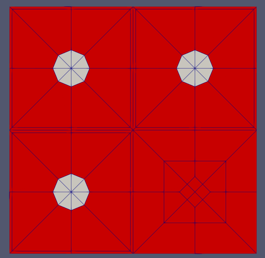
This is the resulting mesh block layout, where by default a single block is assigned to the triangular elements and another block is assigned to the quadrilateral elements:
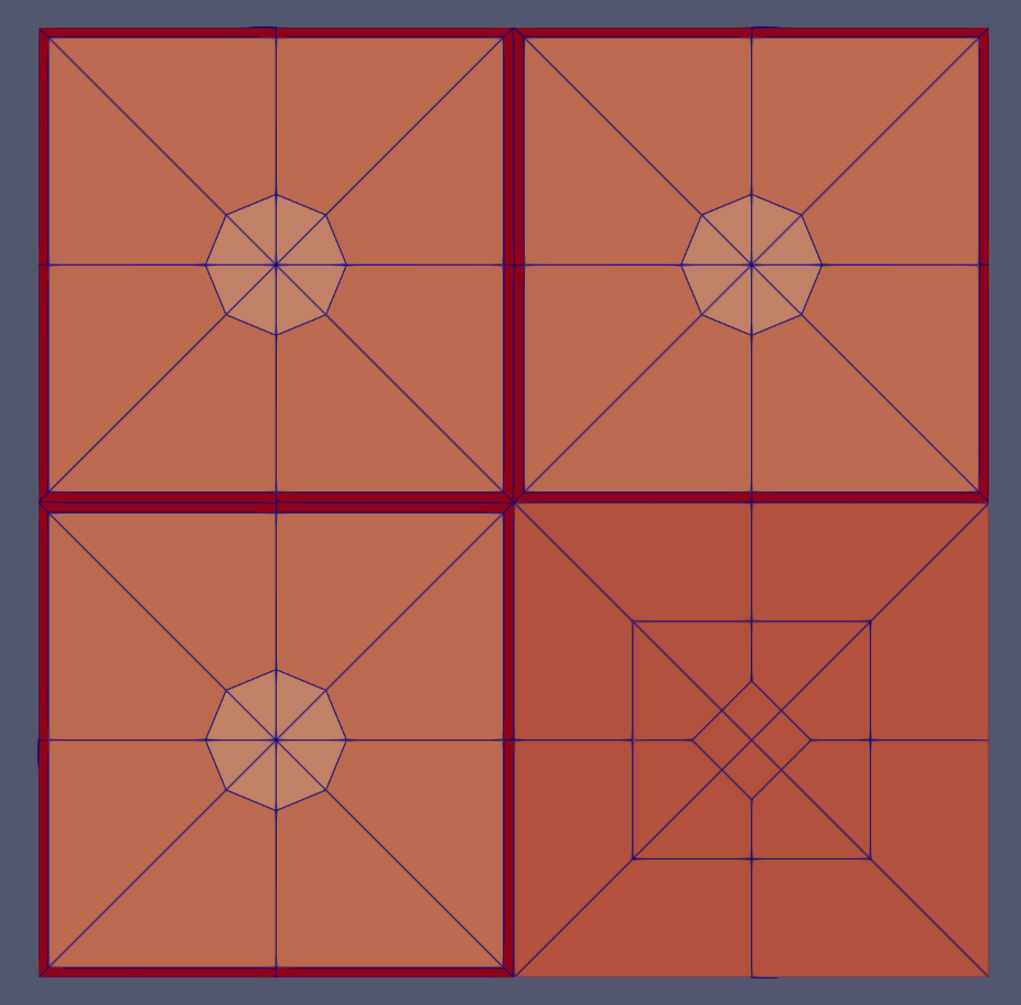
This is the resulting "region_id" extra element integer layout, which was chosen by setting the region IDs for each of the constituent pins:
Input Parameters
- background_block_nameThe block names for the assembly background regions
C++ Type:std::vector<std::string>
Controllable:No
Description:The block names for the assembly background regions
- duct_block_namesThe block names for the assembly duct regions from innermost to outermost
C++ Type:std::vector<std::vector<std::string>>
Controllable:No
Description:The block names for the assembly duct regions from innermost to outermost
- extrudeFalseDetermines if this is the final step in the geometry construction and extrudes the 2D geometry to 3D. If this is true then this mesh cannot be used in further mesh building in the Reactor workflow
Default:False
C++ Type:bool
Controllable:No
Description:Determines if this is the final step in the geometry construction and extrudes the 2D geometry to 3D. If this is true then this mesh cannot be used in further mesh building in the Reactor workflow
Optional Parameters
- assembly_typeThe integer ID for this assembly type definition
C++ Type:unsigned short
Controllable:No
Description:The integer ID for this assembly type definition
Id Assigment Parameters
- background_intervalsRadial intervals in the assembly peripheral region.
C++ Type:unsigned int
Controllable:No
Description:Radial intervals in the assembly peripheral region.
- background_region_idThe region id for the background area between the pins and the ducts to set region_id extra-element integer
C++ Type:std::vector<unsigned short>
Controllable:No
Description:The region id for the background area between the pins and the ducts to set region_id extra-element integer
Background Specifications Parameters
- control_tagsAdds user-defined labels for accessing object parameters via control logic.
C++ Type:std::vector<std::string>
Controllable:No
Description:Adds user-defined labels for accessing object parameters via control logic.
- enableTrueSet the enabled status of the MooseObject.
Default:True
C++ Type:bool
Controllable:No
Description:Set the enabled status of the MooseObject.
- save_with_nameKeep the mesh from this mesh generator in memory with the name specified
C++ Type:std::string
Controllable:No
Description:Keep the mesh from this mesh generator in memory with the name specified
Advanced Parameters
- duct_halfpitchDistance(s) from center to duct(s) inner boundaries.
C++ Type:std::vector<double>
Controllable:No
Description:Distance(s) from center to duct(s) inner boundaries.
- duct_intervalsNumber of meshing intervals in each enclosing duct.
C++ Type:std::vector<unsigned int>
Controllable:No
Description:Number of meshing intervals in each enclosing duct.
- duct_region_idsThe region id for the ducts from innermost to outermost, to set region_id extra-element integer.
C++ Type:std::vector<std::vector<unsigned short>>
Controllable:No
Description:The region id for the ducts from innermost to outermost, to set region_id extra-element integer.
Duct Specifications Parameters
- nemesisFalseWhether or not to output the mesh file in the nemesisformat (only if output = true)
Default:False
C++ Type:bool
Controllable:No
Description:Whether or not to output the mesh file in the nemesisformat (only if output = true)
- outputFalseWhether or not to output the mesh file after generating the mesh
Default:False
C++ Type:bool
Controllable:No
Description:Whether or not to output the mesh file after generating the mesh
- show_infoFalseWhether or not to show mesh info after generating the mesh (bounding box, element types, sidesets, nodesets, subdomains, etc)
Default:False
C++ Type:bool
Controllable:No
Description:Whether or not to show mesh info after generating the mesh (bounding box, element types, sidesets, nodesets, subdomains, etc)
Debugging Parameters
Input Files
- (modules/reactor/test/tests/meshgenerators/assembly_mesh_generator/assembly_only.i)
- (tutorials/tutorial04_meshing/app/test/tests/rgmb_mesh_generators/rgmb_core_hexagonal.i)
- (modules/reactor/test/tests/meshgenerators/core_mesh_generator/core_periphery_prmg.i)
- (tutorials/tutorial04_meshing/app/test/tests/rgmb_mesh_generators/rgmb_core_cartesian.i)
- (tutorials/tutorial04_meshing/app/test/tests/rgmb_mesh_generators/rgmb_core_hexagonal_periphery.i)
- (tutorials/tutorial04_meshing/app/test/tests/reactor_examples/rgmb_lfr/rgmb_lfr_assembly.i)
- (modules/reactor/test/tests/meshgenerators/core_mesh_generator/core_periphery_ptmg_vol.i)
- (modules/reactor/test/tests/meshgenerators/core_mesh_generator/core.i)