Step 5: Secondary Side
Complete input file for this step: 05_secondary_side.i
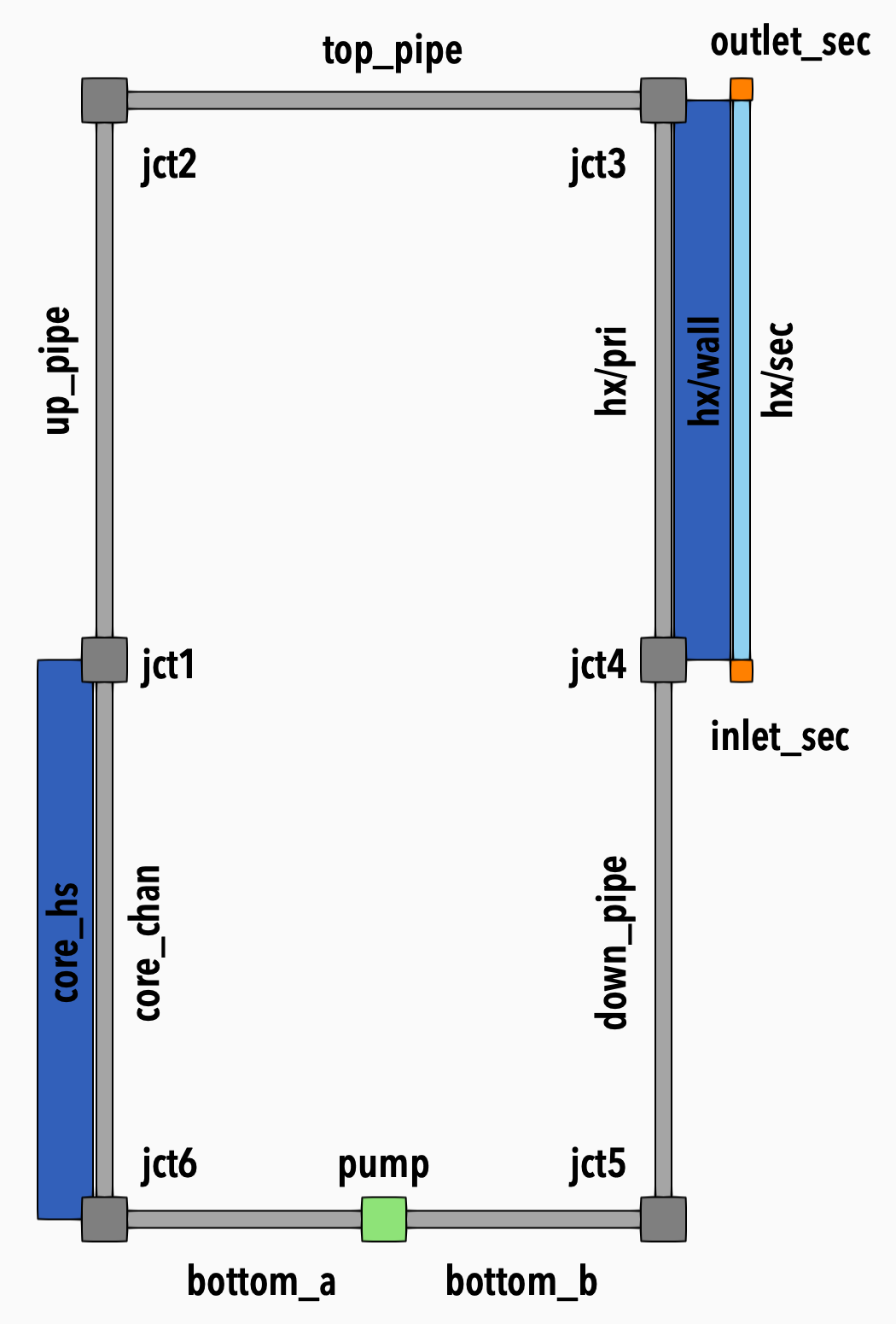
Figure 1: Model diagram
In this step, we will add the secondary side of the heat exchanger and set up the inlet mass flow rate boundary condition as a function of time.
Heat Exchanger
We will define the following heat exchanger parameters:
# heat exchanger parameters
hx_dia_inner = ${units 10. cm -> m}
hx_wall_thickness = ${units 5. mm -> m}
hx_dia_outer = ${units 50. cm -> m}
hx_radius_wall = ${fparse hx_dia_inner / 2. + hx_wall_thickness}
hx_length = 1       # m
hx_n_elems = 10

m_dot_sec_in = 1    # kg/s
We also define second fluid that we will be using on the secondary side:
[water]
  type = StiffenedGasFluidProperties
  gamma = 2.35
  cv = 1816.0
  q = -1.167e6
  p_inf = 1.0e9
  q_prime = 0
[]
Components
To define the heat exchanger block, we will use the syntax for grouping components together.
The general syntax is:
[group]
  [component1]
  []
  [component2]
  []
[]
Then, individual components can be referred to as group/component1 and group/component2.
Note: It is possible to define parameters within the group. Good candidates would be hx_length and hx_n_elems.
We will take advantage of this feature and set our heat exchanger as follows:
[hx]
  [pri]
    type = FlowChannel1Phase
    position = '1 0 2'
    orientation = '0 0 -1'
    length = ${hx_length}
    n_elems = ${hx_n_elems}
    A = '${fparse pi * hx_dia_inner * hx_dia_inner / 4.}'
    D_h = ${hx_dia_inner}
  []

  [ht_pri]
    type = HeatTransferFromHeatStructure1Phase
    hs = hx/wall
    hs_side = inner
    flow_channel = hx/pri
    Hw = 0.97
  []

  [wall]
    type = HeatStructureCylindrical
    position = '1 0 2'
    orientation = '0 0 -1'
    length = ${hx_length}
    n_elems = ${hx_n_elems}
    widths = '${hx_wall_thickness}'
    n_part_elems = '3'
    materials = 'steel'
    names = '0'
    inner_radius = '${fparse hx_dia_inner / 2.}'
  []

  [ht_sec]
    type = HeatTransferFromHeatStructure1Phase
    hs = hx/wall
    hs_side = outer
    flow_channel = hx/sec
    P_hf = '${fparse 2 * pi * hx_radius_wall}'
    Hw = 36
  []

  [sec]
    type = FlowChannel1Phase
    position = '${fparse 1 + hx_wall_thickness} 0 2'
    orientation = '0 0 -1'
    length = ${hx_length}
    n_elems = ${hx_n_elems}
    A = '${fparse pi * (hx_dia_outer * hx_dia_outer / 4. - hx_radius_wall * hx_radius_wall)}'
    D_h = '${fparse hx_dia_outer - (2 * hx_radius_wall)}'
    fp = water
    f = 0.075
  []
[]
Then, we connect the inlet boundary condition to the secondary side flow channel:
[inlet_sec]
  type = InletMassFlowRateTemperature1Phase
  input = 'hx/sec:out'
  m_dot = 0
  T = 300
[]
And then, the outlet boundary condition for the same channel:
[outlet_sec]
  type = Outlet1Phase
  input = 'hx/sec:in'
  p = ${press}
[]
This is the same as what we did in step 1 of this tutorial.
Inlet Mass Flow Rate
To set up the inlet boundary condition as a function of time, we first need to define a time-dependent function in the top-level [Functions] block:
[m_dot_sec_fn]
  type = PiecewiseLinear
  xy_data = '
      0    0
      100 ${m_dot_sec_in}'
[]
In the [ControlLogic] block, we bring the function value in using the GetFunctionValueControl block:
[m_dot_sec_inlet_ctrl]
  type = GetFunctionValueControl
  function = m_dot_sec_fn
[]
And then we feed this value back into the system:
[set_m_dot_sec_ctrl]
  type = SetComponentRealValueControl
  component = inlet_sec
  parameter = m_dot
  value = m_dot_sec_inlet_ctrl:value
[]
Alternative Solution
An alternative solution to this is to use a convenience block called TimeFunctionComponentControl which combines these two ControlLogic blocks into one. It takes three parameters component, parameter, and function.
The equivalent syntax would look like this:
[set_m_dot_sec_ctrl]
  type = TimeFunctionComponentControl
  component = inlet_sec
  parameter = m_dot
  function = m_dot_sec_fn
[]
Note: This should be your preferred setup when you want to use time-dependent component parameters.