MALAMUTE Engineering Scale EFAS Tutorial
Motivation
In the Electric-Field Assisted Sintering (EFAS) process, Joule heating plays a crucial role by generating heat within the tooling and powder sample. As an electric current passes through the conductive tooling and the powder, the materials’ electrical resistance converts electrical energy into thermal energy. This localized heat generation increases the temperature and enables sintering. The heating effect is key to achieving rapid sintering cycles (heating rate, soak time, and cooling rate) and enhanced densification of the powder materials.
This diagram showcases all the components in the DCS-5 tooling stack:
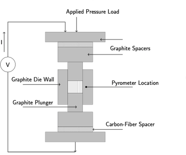
There is a uniaxial pressure due to steel rams that are placed on the top of the tooling stack as shown by the applied pressure load in the diagram. The graphite plungers on the top and the bottom of the tooling stack allow for temperature distribution onto the powder and apply the intended uniaxial pressure.
To mitigate the temperatures to which the EFAS machine steel rams are exposed, Carbon-fiber Reinforced Carbon plates are used as an additional spacer between the small graphite spacer and the larger ram-adjacent spacer to reduce heat transfer from the graphite stack Preston et al. (2024).
The graphite die wall insulates the powder material and conducts heat onto the material to allow for the desired processes to occur. There is also a pyrometer inserted a certain length into the die wall, varying based on the die wall thickness. This pyrometer provides the necessary data to the EFAS machine, so that the powder is heated to suitable temperatures at the correct times.
Temperature distribution as a function of die geometry is crucial in the EFAS process. The high thermal conductivity of graphite, which is used as the material for the die in this tutorial, allows for rapid heat distribution. A thicker die wall could enhance this effect, potentially promoting a more uniform temperature throughout the die as there is more material available to absorb and evenly distribute the heat, according to Fourier’s law: greater thickness of material leads to lower heat flux, thus a lower temperature gradient and a more uniform temperature. Conversely, a die wall that is too thin might not effectively manage temperature gradients (less heat retained in tooling material Preston et al. (2024)). It is therefore essential to optimize the die wall thickness to ensure consistent heating and the integrity of the sintering process.
Objective
Here we will perform a basic one-factor study involving a parametric analysis, limiting the independent variable to five different die wall thicknesses (e.g., 5 mm, 10 mm, 13.875 mm, 20 mm, 25 mm).
die_wall_thickness = 0.013875
The die wall thickness is shown above and on Line 55 of the input file. This value has units in meters, and the units should be converted accordingly. Each thickness could correspond to a separate input file in MALAMUTE, creating five distinct simulations for comparison.
The primary objective of this tutorial is to examine how the temperature distribution within the DCS-5 tooling stack varies with die wall thickness. We will achieve this goal by utilizing temperature contour fields to identify any patterns of temperature localization that might emerge. While the temperature of the powder itself is not measured directly, this study aims to discern trends that link the observed temperature distribution within the die to the likely temperature of the powder. The analysis is further improved by outputting the temperature at the approximate pyrometer location throughout the simulation. Time versus history graphs and temperature contour fields will both be used to provide a visual representation of the data. Analysis of these results will be completed to determine the impact of the die wall thickness on the temperature evolution as predicted by this series of MALAMUTE simulations.
Assumptions
A major assumption in this tutorial is that the material properties are constant, and do not vary with temperature, for all three materials (copper, graphite, C-C fiber) in the simulation. The impact of this assumption is that the simulation will predict temperatures that are greater than EFAS run temperatures as measured with a pyrometer. Nonetheless, the trends in the temperature time history and 2D temperature contour maps help us understand how the die wall thickness affects the temperature fields within the EFAS machine around the powder.
References
- Arin S. Preston, Andrew J. Gorman, Austin C. Matthews, and Jorgen F. Rufner.
3d printed carbon fiber reinforced carbon as an energy efficient alternative to graphite for efas tooling.
Composites Part B: Engineering, 283:111679, 2024.
doi:https://doi.org/10.1016/j.compositesb.2024.111679.[BibTeX]