Step 4: Primary Loop
Complete input file for this step: 04_loop.i
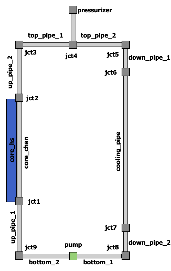
Figure 1: Model diagram
In this step, we will complete the primary loop and set up a simple PID controller for the pump so that it maintains the prescribed mass flow rate.
Close the Loop
We add two pipes for the bottom section of the primary loop with a pump in the middle. A pump is a junction-like component that connects to two flow channels corresponding to its inlet and outlet.
  [jct7]
    type = JunctionOneToOne1Phase
    connections = 'cooling_pipe:out down_pipe_2:in'
  []

  [down_pipe_2]
    type = FlowChannel1Phase
    position = '1 0 0.25'
    orientation = '0 0 -1'
    length = 0.25
    n_elems = 10
    A = ${A_pipe}
    D_h = ${pipe_dia}
  []
The pump component needs 2 more parameters to be specified: reference area A_ref, and head, which is the pump head.
Because the system is now closed, we add a simple pressurizer to maintain the system pressure as the fluid heats up. We split the pipe at the top to create a T-junction with a pipe connected to the pressurizer using a VolumeJunction1Phase. The pressurizer is modeled by prescribing the stagnation pressure with an InletStagnationPressureTemperature1Phase component.
  [jct4]
    type = VolumeJunction1Phase
    position = '0.5 0 2'
    volume = 1e-5
    connections = 'top_pipe_1:out top_pipe_2:in press_pipe:in'
  []

  [press_pipe]
    type = FlowChannel1Phase
    position = '0.5 0 2'
    orientation = '0 0 1'
    length = 0.2
    n_elems = 5
    A = ${A_pipe}
    D_h = ${pipe_dia}
  []

  [pressurizer]
    type = InletStagnationPressureTemperature1Phase
    p0 = ${press}
    T0 = ${T_in}
    input = press_pipe:out
  []
Control Logic
The ChainControls system allows users to monitor the simulation and change its parameters while it is running.
The system consists of 3 layers:
input layer: which brings values from the simulation inside the control data system
execution layer: which performs the prescribed operations
output layer: that feeds the values back into simulation
All control blocks should be included in the top-level [ChainControls] block. Here, each control sets execute_on = 'INITIAL TIMESTEP_BEGIN' so that the controlled parameters are updated before each time step is solved; by default, controls execute at the end of the time step.
Setup PID
A PID control requires several values as an input: set point set_point, input value input, initial integral initial_integral, and three constants K_p, K_i, and K_d, which are the coefficients for the proportional, integral, and derivative terms, respectively.
For the input value, we set up a postprocessor m_dot_pump with type ADFlowJunctionFlux1Phase which will be measuring the outlet mass flow rate from the pump.
[Postprocessors<<<{"href": "../../../../syntax/Postprocessors/index.html"}>>>]
  [m_dot_pump]
    type = ADFlowJunctionFlux1Phase<<<{"description": "Retrieves an entry of a flux vector for a connection attached to a 1-phase junction", "href": "../../../../source/postprocessors/ADFlowJunctionFlux1Phase.html"}>>>
    boundary<<<{"description": "The list of boundary IDs from the mesh where this object applies"}>>> = core_chan:in
    connection_index<<<{"description": "Index of the connected flow channel"}>>> = 1
    equation<<<{"description": "Equation for which to query flux vector"}>>> = mass
    junction<<<{"description": "Junction component name"}>>> = jct7
  []
[]
To bring this value into the control data system, we use a GetPostprocessorChainControl block. Setting name_data_same_as_postprocessor = true makes the control data available under the name of the postprocessor, m_dot_pump:
[ChainControls<<<{"href": "../../../../syntax/ChainControls/index.html"}>>>]
  [get_m_dot_pump]
    type = GetPostprocessorChainControl<<<{"description": "Copies a post-processor value into a ChainControlData.", "href": "../../../../source/chaincontrols/GetPostprocessorChainControl.html"}>>>
    execute_on<<<{"description": "The list of flag(s) indicating when this object should be executed. For a description of each flag, see https://mooseframework.inl.gov/source/interfaces/SetupInterface.html."}>>> = 'INITIAL TIMESTEP_BEGIN'
    postprocessor<<<{"description": "Post-processor name"}>>> = m_dot_pump
    name_data_same_as_postprocessor<<<{"description": "If true, name the new control data to be the same as the post-processor name; otherwise name as '<control>:value', where '<control>' is the name of this control object."}>>> = true
  []
[]
A set point will be our desired mass flow rate specified by the global parameter m_dot_in. To bring this value into the control data system, we need to use a GetFunctionValueChainControl block like so:
[ChainControls<<<{"href": "../../../../syntax/ChainControls/index.html"}>>>]
  [set_point]
    type = GetFunctionValueChainControl<<<{"description": "Creates a control data and populates it by evaluating a Function.", "href": "../../../../source/chaincontrols/GetFunctionValueChainControl.html"}>>>
    execute_on<<<{"description": "The list of flag(s) indicating when this object should be executed. For a description of each flag, see https://mooseframework.inl.gov/source/interfaces/SetupInterface.html."}>>> = 'INITIAL TIMESTEP_BEGIN'
    function<<<{"description": "Function to be evaluated"}>>> = ${m_dot_in}
  []
[]
This value will be available in the control data system as set_point:value (in general control_block_name:value).
Then, we add the PID control block, PIDChainControl, as follows:
[ChainControls<<<{"href": "../../../../syntax/ChainControls/index.html"}>>>]
  [pid]
    type = PIDChainControl<<<{"description": "Implements a proportional-integral-derivative (PID) controller.", "href": "../../../../source/chaincontrols/PIDChainControl.html"}>>>
    execute_on<<<{"description": "The list of flag(s) indicating when this object should be executed. For a description of each flag, see https://mooseframework.inl.gov/source/interfaces/SetupInterface.html."}>>> = 'INITIAL TIMESTEP_BEGIN'
    initial_integral<<<{"description": "Initial value for the integral component"}>>> = 0
    set_point<<<{"description": "Set point control data"}>>> = set_point:value
    input<<<{"description": "Input control data"}>>> = m_dot_pump
    K_p<<<{"description": "Coefficient for the proportional term"}>>> = 1.
    K_i<<<{"description": "Coefficient for the integral term"}>>> = 4.
    K_d<<<{"description": "Coefficient for the derivative term"}>>> = 0
  []
[]
The value computed by the PID control is available in the control data system under the name pid:value, where pid is the name of the block.
As a last step, we need to feed this value back into the system. That can be done via a SetValueChainControl block.
[ChainControls<<<{"href": "../../../../syntax/ChainControls/index.html"}>>>]
  [set_pump_head]
    type = SetRealValueChainControl<<<{"description": "Sets parameter(s) of type 'double' to a control data value of type 'double'.", "href": "../../../../source/chaincontrols/SetValueChainControl.html"}>>>
    execute_on<<<{"description": "The list of flag(s) indicating when this object should be executed. For a description of each flag, see https://mooseframework.inl.gov/source/interfaces/SetupInterface.html."}>>> = 'INITIAL TIMESTEP_BEGIN'
    parameter<<<{"description": "Parameter(s) to control"}>>> = component::pump/head
    value<<<{"description": "Control data to use for the value of the parameter(s)"}>>> = pid:value
  []
[]
The parameter to control is specified via the parameter parameter. For a component parameter, it has the form component::<component_name>/<parameter_name>, where <component_name> and <parameter_name> are the component name and the parameter name of that component we want to modify.