Injection and production wells coupling
This example simulates injection and production wells coupled to a subsurface porous matrix containing 3 fractures. The injection and production wells are modeled using 1D flow channel components and 0D junctions from MOOSE's thermal hydraulics module. The porous matrix is 3D, with embedded 2D fracture planes, modeled using MOOSE's porous flow module.
Problem Description
In this problem, water is injected into a well at a surface location. This injection well has 3 subsurface apertures which couple to a 3D porous matrix. At some distance away, a production well extracts water from the porous matrix, also through 3 apertures. The transient has 3 phases:
: Coupling startup phase: .
: Inlet mass flow rate ramp phase: , where .
: Approach to steady-state: .
Implementation Overview
The InjectionWell and ProductionWell components are used to create the 1D injection and production wells, respectively, which are each composed of multiple 1D flow channels (FlowChannel1Phase), connected by 0D volume junctions (VolumeJunction1Phase). The InjectionWell and ProductionWell components also create the coupling between the 1D wells and the 3D porous matrix using VolumeJunctionCoupledFlux1Phase components. On the porous matrix side, CoupledInjectionProduction is used to apply the coupling terms.
Running the Example
There are two options for the main input file:
fracs_main.i: models the wells and fractures using a MultiApp approach, with the fractures being the main app.wells_main.i: models the wells and fractures using a MultiApp approach, with the wells being the main app.
Results
There is a plot script that can be run as follows, which plots output from both runs:
python plot.py
The results obtained from fracs_main.i are shown in Figure 1.
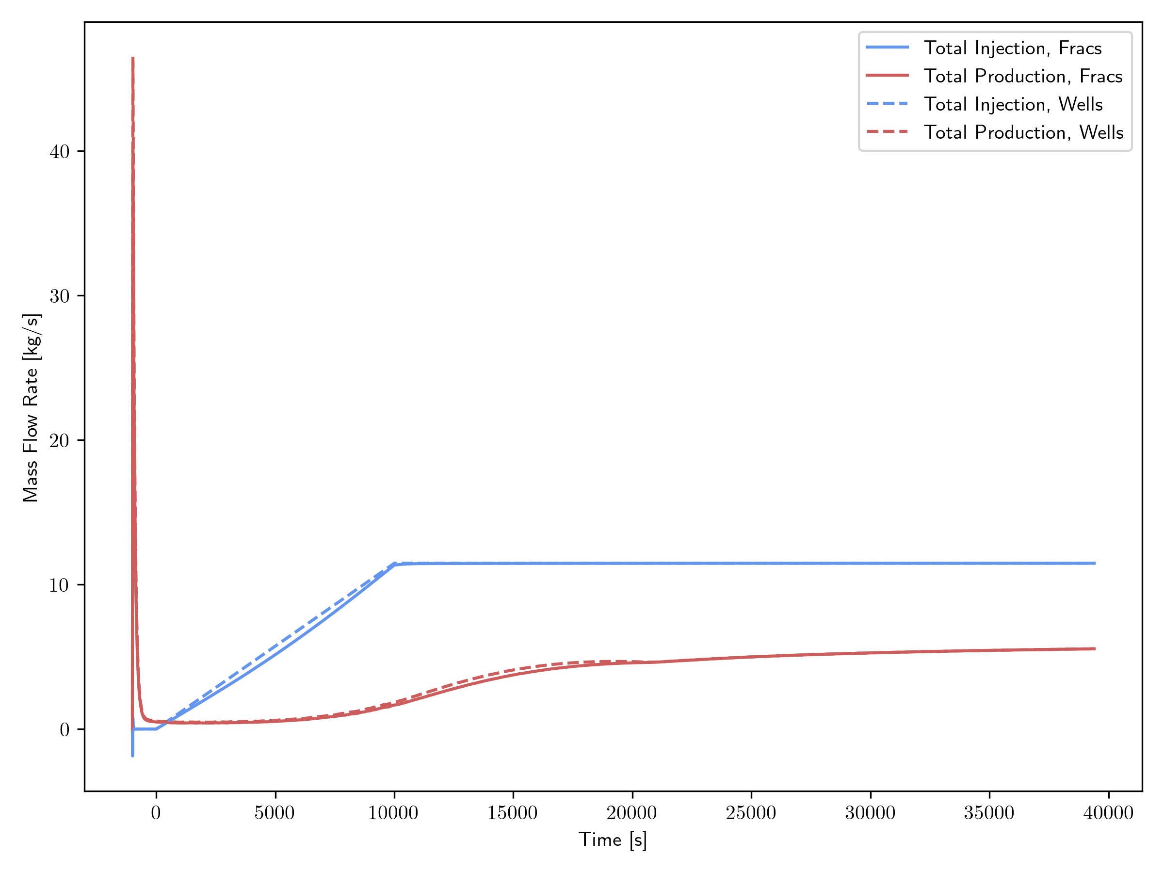
Figure 1: Mass flow rate transient results obtained using fracs_main.i.
There are 4 sets shown on the plot:
"Total Injection, Fracs": sum of the mass flow rates from the injection well to the porous matrix at each of the injection points.
"Total Production, Fracs": sum of the mass flow rates from the porous matrix to the production well at each of the production points.
"Total Injection, Wells": total mass flow rate at injection well inlet.
"Total Production, Wells": total mass flow rate at production well outlet.
At the beginning of the transient, there are a short-duration spikes in both the production and injection, which is due to the discrepancy in initial pressures of the wells and the 3D porous matrix coupling points. While both domains use the same initial pressure profile, the interpolations to the respective meshes differ, thus resulting into an artificial transient.
As mass is injected into the injection well inlet, note a small lag of the total injection mass flow rate into the porous matrix. The production mass flow rates responds relatively slowly to this mass injection, due to some of the water finding other outlets in the domain. At the steady state, the production mass flow rate is roughly 40% of the inlet mass flow rate.