Inclined Crack in Infinite Plate
The following example follows from Moës et al. (1999), Richardson et al. (2011), and Belytschko and Black (1999) where the stress intensity factors for a plate with an angled center crack is subjected to a far-field load in the y-direction. The analytic solution for the stress intensity factors of the configuration shown in Figure 1 is given by
(1)
where the crack angle with respect to the x-axis is , the crack length is and the far-field load . Convergence with global mesh refinement to the analytic solution is shown for a range of crack orientations in Figure 3. The values for in blue show better convergence than shown in red for mixed mode loading of the crack-tip when . Figure 2 shows the q-function for integrating the J-integral. Incorrectly specifying the radii for the q-function will lead to inaccurate calculation of the J-integral and stress intensity factors. The q-function should exclude a few elements around the crack tip where . The q-function radii are designated in the DomainIntegral block shown in Listing 1. This example uses a cutter mesh, shown by the white line in Figure 1, to create the initial crack using the MeshCut2DFractureUserObject object, also shown in Listing 1.
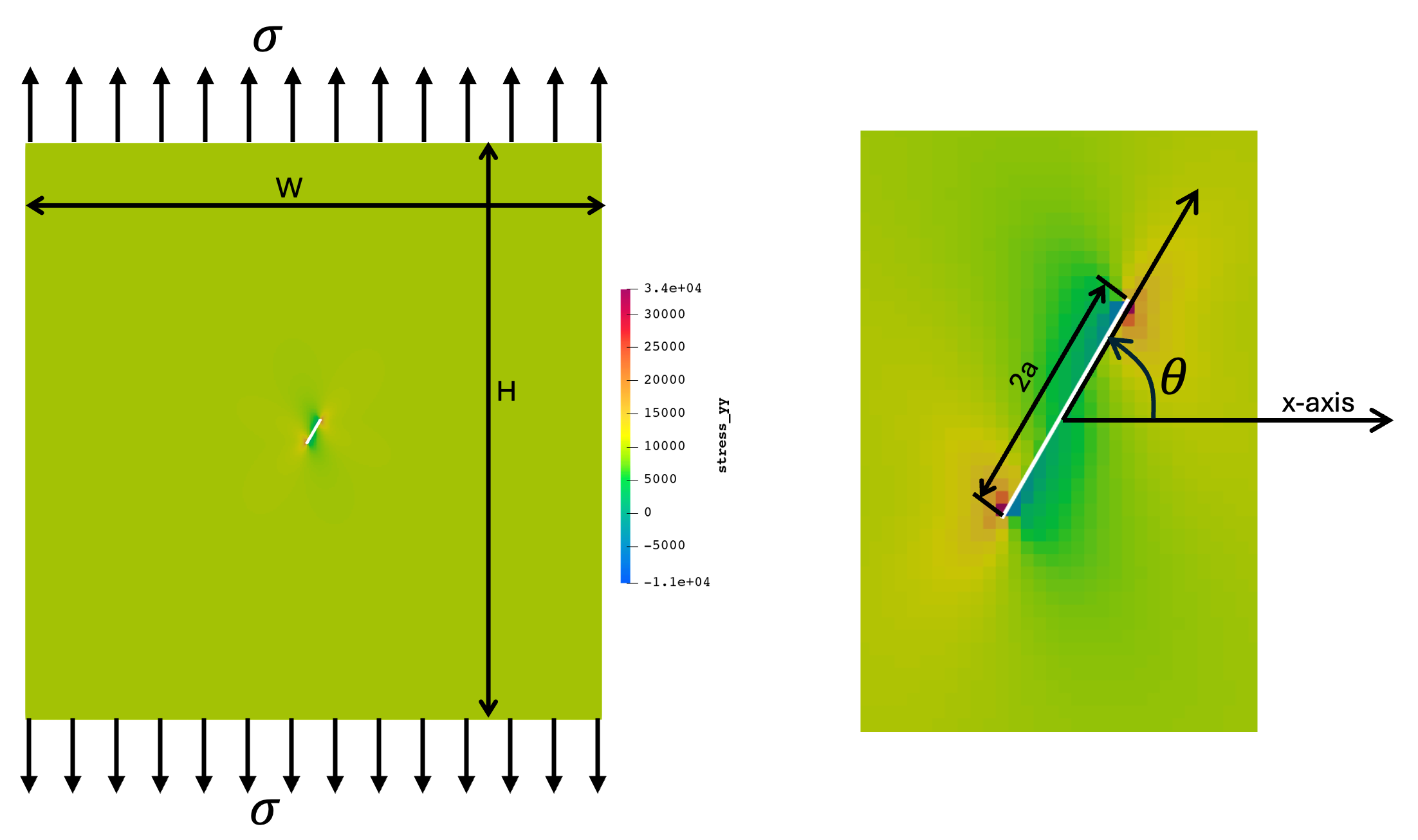
Figure 1: Left: Inclined plate simulation domain showing the stress field in the y-direction. The mesh dimensions are and the crack length is . The white line in the center is the inclined crack created by the XFEM cutter mesh. Right: Close up of crack geometry with labels.
. The initial XFEM cut created by the `MeshCut2DFractureUserObject` is also shown.](../../../../large_media/xfem/q1_field_label.png)
Figure 2: Domain integral integration field (q-function) around the bottom crack-tip. The integration field is integrated over the area between r_inner and r_outer specified in the DomainIntegral block in Listing 1. The initial XFEM cut created by the MeshCut2DFractureUserObject is also shown.
 and [!ref](qintegral) are for h=0.1.](../../../../large_media/xfem/incline_angle_convergence.png)
Listing 1: Input file for inclined crack.
[UserObjects<<<{"href": "../../../../syntax/UserObjects/index.html"}>>>]
  [cut_mesh]
    type = MeshCut2DFractureUserObject<<<{"description": "XFEM mesh cutter for 2D models that defines cuts with amesh and uses fracture integrals to determine growth", "href": "../../../../source/userobjects/MeshCut2DFractureUserObject.html"}>>>
    mesh_generator_name<<<{"description": "Mesh generator for the XFEM geometric cutter."}>>> = 'cut_mesh'
    growth_increment<<<{"description": "Length to grow crack if k>k_critical or stress>stress_threshold"}>>> = 0.05
    ki_vectorpostprocessor<<<{"description": "The name of the vectorpostprocessor that contains KI"}>>> = "II_KI_1"
    kii_vectorpostprocessor<<<{"description": "The name of the vectorpostprocessor that contains KII"}>>> = "II_KII_1"
    k_critical<<<{"description": "Critical fracture toughness."}>>> = 1000 # big, don't want to grow
  []
[]

[DomainIntegral<<<{"href": "../../../../syntax/DomainIntegral/index.html"}>>>]
  integrals<<<{"description": "Domain integrals to calculate.  Choices are: JIntegral CIntegral KFromJIntegral InteractionIntegralKI InteractionIntegralKII InteractionIntegralKIII InteractionIntegralT"}>>> = 'Jintegral InteractionIntegralKI InteractionIntegralKII'
  displacements<<<{"description": "The displacements appropriate for the simulation geometry and coordinate system"}>>> = 'disp_x disp_y'
  crack_front_points_provider<<<{"description": "The UserObject provides the crack front points from XFEM GeometricCutObject"}>>> = cut_mesh
  2d<<<{"description": "Treat body as two-dimensional"}>>> = true
  number_points_from_provider<<<{"description": "The number of crack front points, only needed for crack_front_points_provider that do not use a cut mesh."}>>> = 2
  crack_direction_method<<<{"description": "Method to determine direction of crack propagation.  Choices are: CrackDirectionVector CrackMouth CurvedCrackFront"}>>> = CurvedCrackFront
  radius_inner<<<{"description": "Inner radius for volume integral domain"}>>> = '0.2'
  radius_outer<<<{"description": "Outer radius for volume integral domain"}>>> = '0.8'
  poissons_ratio<<<{"description": "Poisson's ratio"}>>> = ${poissons}
  youngs_modulus<<<{"description": "Young's modulus"}>>> = ${youngs}
  block<<<{"description": "The block ids where integrals are defined"}>>> = 0
  incremental<<<{"description": "Flag to indicate whether an incremental or total model is being used."}>>> = false
[]The maximum circumferential (hoop) stress criterion is used to determine the crack growth direction Erdogan and Sih (1963). This criterion is used in xfem crack growth implementations by Belytschko and Black (1999) and Jiang et al. (2020). For this criterion, the crack will grow in the local crack tip direction that maximizes the hoop stress given in terms of and by (2)
By setting other crack tip stress components to zero to maximize the the stress normal to the crack face, the critical crack tip growth direction is given by (3) where the is determined by the that maximizes . Simulation and analytical results for the crack tip direction using equation Eq. (1) are shown in the below figure for the coarsest mesh from Figure 3. The crack growth direction at each end of the inclined crack computed by the MeshCut2DFractureUserObject is shown by the '◻' and '' markers. These results match the results computed by plugging in and from Figure 3 for h=0.2 into Eq. (2) and Eq. (3) shown by the '●'. The simulation results converge to the analytic solution with mesh refinement, as was shown for convergence of and in Figure 3.
![Crack growth direction from equations [eq:sigma] and [eq:theta] for h=0.2 from [!ref](convergence).](../../../../large_media/xfem/crackGrowthDir.png)
References
- T. Belytschko and T. Black.
Elastic crack growth in finite elements with minimal remeshing.
International Journal for Numerical Methods in Engineering, 45(5):601–620, June 1999.
doi:10.1002/(SICI)1097-0207(19990620)45:5<601::AID-NME598>3.0.CO;2-S.[Export]
- F Erdogan and GC Sih.
On the crack extension in plates under plane loading and transverse shear.
Journal of Basic Engineering, 85(4):519–525, 1963.[Export]
- Wen Jiang, Benjamin W. Spencer, and John E. Dolbow.
Ceramic nuclear fuel fracture modeling with the extended finite element method.
Engineering Fracture Mechanics, 223:106713, 2020.
URL: http://www.sciencedirect.com/science/article/pii/S0013794419307568, doi:https://doi.org/10.1016/j.engfracmech.2019.106713.[Export]
- Nicolas Moës, John Dolbow, and Ted Belytschko.
A finite element method for crack growth without remeshing.
International Journal for Numerical Methods in Engineering, 46(1):131–150, 1999.
doi:10.1002/(SICI)1097-0207(19990910)46:1<131::AID-NME726>3.0.CO;2-J.[Export]
- Casey L. Richardson, Jan Hegemann, Eftychios Sifakis, Jeffrey Hellrung, and Joseph M. Teran.
An XFEM method for modeling geometrically elaborate crack propagation in brittle materials.
International Journal for Numerical Methods in Engineering, 88(10):1042–1065, 2011.
doi:10.1002/nme.3211.[Export]