Recuperated Brayton Cycle
Introduction
As shown in the Brayton Cycle modelingguide, and the given input files closed_brayton_cycle.i and open_brayton_cycle.i, a Brayton Cycle Power Conversion Unit (PCU) consists of a motor, compressor, turbine, and generator all coupled by a single shaft.
Detailed descriptions of the compressor and turbine components used in this example can be found in the Brayton Cycle modeling guide. In the aforementioned example, a simplified startup transient with a simplified heat source was conducted which demonstrated the Thermal Hydraulics module’s capability to produce torque, power, mass flow rate, and pressure ratios for all PCU components based on the shaft speed.
In this example a different heat source and recuperator were added to the same open Brayton Cycle PCU to demonstrate a more nuanced model along with a more realistic piping structure. Also, a Proportional-Integral-Derivative (PID) controller was added to the motor to conduct a more realistic startup transient of the system.
A heat rate of 105.75 kW is applied as a uniform volumetric source to a 10-m-long steel tube with an outer radius of 15 cm. Gas which has been compressed in the compressor, and preheated in the recuperator, passes over the exterior of the heat structure and removes heat via forced convection.
The recuperator is represented by an annular cylindrical heat structure of the same material and width as the main heat source but only 5 m in length and without internal heat generation. Instead, hot exhaust gas leaving the turbine transfers heat to the inside of the recuperator, and cooler gas from the compressor outlet removes heat from the outer surface. This preheats the gas entering the main heat source and improves thermal efficiency of the cycle.
Transient Description
Initially the shaft system is at rest, and the working fluid and heat structures are the ambient temperature and pressure. At t = 0 s the motor PID activates and ramps the PCU shaft to approximately 87,000 RPM over the course of 1600 s. When t = 1000 s, heat generation in the main heat structure is activated and linearly increases from 0 kW to a maximum power of 105.75 kW by t = 8600 s.
As the working fluid begins to heat, torque supplied to the shaft from the turbine increases. The motor PID control logic slowly decreases the torque supplied by the motor to 0 N·m once the turbine torque is greater than the torque supplied by the motor. This allows for a graceful transition of PCU control from the motor PID to the working fluid and heat source, and prevents drastically over-speeding the system above the rated speed of 96,000 RPM.
Input File description
The recuperated Brayton Cycle example is executed with the input file recuperated_brayton_cycle.i. Shown below in Figure 1 is a diagram of the modeled system.
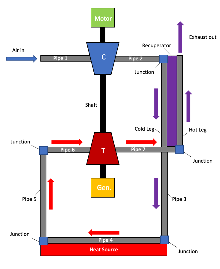
Figure 1: Diagram of the recuperated Brayton Cycle.
All 90° pipe bends are modeled using VolumeJunction1Phase as shown in the example below:
[Components<<<{"href": "../../../../syntax/Components/index.html"}>>>]
  [junction2_cold_leg]
    type = VolumeJunction1Phase<<<{"description": "Junction between 1-phase flow channels that has a non-zero volume", "href": "../../../../source/components/VolumeJunction1Phase.html"}>>>
    connections<<<{"description": "Junction connections"}>>> = 'pipe2:out cold_leg:in'
    position<<<{"description": "Spatial position of the center of the junction [m]"}>>> = '${x3} ${y3} 0'
    volume<<<{"description": "Volume of the junction [m^3]"}>>> = '${fparse A2*0.1}'
  []
[]
The main heat source is modeled as a heat structure with internal heat generation and forced convection heat transfer to Pipe 4.
[Components<<<{"href": "../../../../syntax/Components/index.html"}>>>]
  [reactor]
    type = HeatStructureCylindrical<<<{"description": "Cylindrical heat structure", "href": "../../../../source/components/HeatStructureCylindrical.html"}>>>
    orientation<<<{"description": "Direction of axis from start position to end position (no need to normalize)"}>>> = '-1 0 0'
    position<<<{"description": "Start position of axis in 3-D space [m]"}>>> = '${x4} ${y4} 0'
    length<<<{"description": "Length of each axial section [m]"}>>> = ${L4}
    widths<<<{"description": "Width of each radial region [m]"}>>> = 0.15
    n_elems<<<{"description": "Number of elements in each axial section"}>>> = ${n_elems4}
    n_part_elems<<<{"description": "Number of elements of each radial region"}>>> = 2
    names<<<{"description": "Name of each radial region"}>>> = core
    solid_properties<<<{"description": "Solid properties object name for each radial region"}>>> = steel
    solid_properties_T_ref<<<{"description": "Density reference temperatures for each radial region. This is required if 'solid_properties' is provided. The density in each region will be a constant value computed by evaluating the density function at the reference temperature."}>>> = '300'
  []
[]
[Components<<<{"href": "../../../../syntax/Components/index.html"}>>>]
[total_power]
type = TotalPower<<<{"description": "Prescribes total power via a user supplied value", "href": "../../../../source/components/TotalPower.html"}>>>
power<<<{"description": "Total power [W]"}>>> = 0
[]
[][Components<<<{"href": "../../../../syntax/Components/index.html"}>>>]
[heat_generation]
type = HeatSourceFromTotalPower<<<{"description": "Heat generation from total power", "href": "../../../../source/components/HeatSourceFromTotalPower.html"}>>>
power<<<{"description": "Component that provides total power"}>>> = total_power
hs<<<{"description": "Heat structure in which to apply heat source"}>>> = reactor
regions<<<{"description": "Heat structure regions where heat generation is to be applied"}>>> = core
[]
[][Components<<<{"href": "../../../../syntax/Components/index.html"}>>>]
[heat_transfer]
type = HeatTransferFromHeatStructure1Phase<<<{"description": "Connects a 1-phase flow channel and a heat structure", "href": "../../../../source/components/HeatTransferFromHeatStructure1Phase.html"}>>>
flow_channel<<<{"description": "Name of flow channel component to connect to"}>>> = pipe4
hs<<<{"description": "Heat structure name"}>>> = reactor
hs_side<<<{"description": "Heat structure side"}>>> = OUTER
Hw<<<{"description": "Convective heat transfer coefficient [W/(m^2-K)]"}>>> = 10000
[]
[]The Recuperator is modeled as a heat structure without internal heat generation and heat transfer to both cold_leg and hot_leg.
[Components<<<{"href": "../../../../syntax/Components/index.html"}>>>]
  [recuperator]
    type = HeatStructureCylindrical<<<{"description": "Cylindrical heat structure", "href": "../../../../source/components/HeatStructureCylindrical.html"}>>>
    orientation<<<{"description": "Direction of axis from start position to end position (no need to normalize)"}>>> = '0 -1 0'
    position<<<{"description": "Start position of axis in 3-D space [m]"}>>> = '${x3} ${y3} 0'
    length<<<{"description": "Length of each axial section [m]"}>>> = '${fparse L3/2}'
    widths<<<{"description": "Width of each radial region [m]"}>>> = ${recuperator_width}
    n_elems<<<{"description": "Number of elements in each axial section"}>>> = '${fparse n_elems3/2}'
    n_part_elems<<<{"description": "Number of elements of each radial region"}>>> = 2
    names<<<{"description": "Name of each radial region"}>>> = recuperator
    solid_properties<<<{"description": "Solid properties object name for each radial region"}>>> = steel
    solid_properties_T_ref<<<{"description": "Density reference temperatures for each radial region. This is required if 'solid_properties' is provided. The density in each region will be a constant value computed by evaluating the density function at the reference temperature."}>>> = '300'
    inner_radius<<<{"description": "Inner radius of the heat structure [m]"}>>> = ${D1}
  []
[]
[Components<<<{"href": "../../../../syntax/Components/index.html"}>>>]
[heat_transfer_cold_leg]
type = HeatTransferFromHeatStructure1Phase<<<{"description": "Connects a 1-phase flow channel and a heat structure", "href": "../../../../source/components/HeatTransferFromHeatStructure1Phase.html"}>>>
flow_channel<<<{"description": "Name of flow channel component to connect to"}>>> = cold_leg
hs<<<{"description": "Heat structure name"}>>> = recuperator
hs_side<<<{"description": "Heat structure side"}>>> = OUTER
Hw<<<{"description": "Convective heat transfer coefficient [W/(m^2-K)]"}>>> = 10000
[]
[][Components<<<{"href": "../../../../syntax/Components/index.html"}>>>]
[heat_transfer_hot_leg]
type = HeatTransferFromHeatStructure1Phase<<<{"description": "Connects a 1-phase flow channel and a heat structure", "href": "../../../../source/components/HeatTransferFromHeatStructure1Phase.html"}>>>
flow_channel<<<{"description": "Name of flow channel component to connect to"}>>> = hot_leg
hs<<<{"description": "Heat structure name"}>>> = recuperator
hs_side<<<{"description": "Heat structure side"}>>> = INNER
Hw<<<{"description": "Convective heat transfer coefficient [W/(m^2-K)]"}>>> = 10000
[]
[]Control Logic
One of the main changes from the Brayton Cycle modeling guide is the addition of a PID controller to the motor for the start up transient. This PID control operates a 3-Phase electric motor which applies torque to the shaft to reach a desired speed set by the user, in this case 87,000 RPM. A speed lower than the rated turbine speed of 96,000 RPM was chosen to prevent significant over-speeding of the turbine during the start up transient.
As the shaft increases in speed, the compressor begins to compress the inlet atmospheric air and produces a coolant flow through the system. Once the heat source begins heating the coolant, the gas begins conducting work on the system via the turbine. However, until a fully developed and fully heated flow is established, the working fluid still requires an assist from the motor to maintain shaft speed and adequate coolant mass flow rate. At this point, a direct shutoff of the motor would cause the system to stall. Conversely, if the motor were to supply a constant torque the shaft would over speed due to the increasing torque supplied by the turbine from the heating coolant.
To prevent stalling or significant over-speeding of the shaft while the coolant is reaching a fully developed and fully heated flow, a shutdown function is applied to the motor. A linearly decreasing torque is applied to the motor starting from the time the turbine first provides more torque and reaches 0 N·m after 35,000 s. This function uses ControlLogic to determine when the torque supplied by the turbine is greater than the motor, and initiates a graceful ramp down of the motor. The proceeding sections discuss in detail how this control logic is implemented in the input file.
PID Control
Shown below is the ControlLogic block containing the PID block utilizing PIDControl. Here, the , , and variables are the proportional, integral, and derivative gains respectively. As with any PID control, gains must be determined for a specific system and are not universal. In this specific PID, the output signal is used to govern the torque supplied by the motor to the system shaft based upon the current shaft speed.
[ControlLogic<<<{"href": "../../../../syntax/ControlLogic/index.html"}>>>]
  [initial_motor_PID]
    type = PIDControl<<<{"description": "Declares a control data named 'output' and uses Proportional Integral Derivative logic on the 'value' control data to set it.", "href": "../../../../source/controllogic/PIDControl.html"}>>>
    set_point<<<{"description": "The name of the control data with the set point."}>>> = set_point:value
    input<<<{"description": "The name of the control data that we read in."}>>> = shaft_RPM
    initial_value<<<{"description": "The initial value for the integral part."}>>> = 0
    K_p<<<{"description": "The coefficient for the proportional term."}>>> = 0.0011
    K_i<<<{"description": "The coefficient for the integral term."}>>> = 0.00000004
    K_d<<<{"description": "The coefficient for the derivative term."}>>> = 0
  []
[]
The PID attempts to reach a desired shaft speed, in RPM, which is determined by the set_point block using GetFunctionValueControl. The rated speed of the turbine is set at the beginning of the input file as a global parameter speed_rated_rpm. To prevent over-speeding of the turbine and compressor, the set point of the PID is adjusted to be lower than the rated turbine speed.
[ControlLogic<<<{"href": "../../../../syntax/ControlLogic/index.html"}>>>]
  [set_point]
    type = GetFunctionValueControl<<<{"description": "Sets a ControlData named 'value' with the value of a function", "href": "../../../../source/controllogic/GetFunctionValueControl.html"}>>>
    function<<<{"description": "The name of the function prescribing a value."}>>> = '${fparse speed_rated_rpm - 9000}'
  []
[]
A ParsedFunctionControl is applied to determine whether to send the PID output to the motor or shutdown the motor because the turbine is supplying enough torque.
[ControlLogic<<<{"href": "../../../../syntax/ControlLogic/index.html"}>>>]
  [logic]
    type = ParsedFunctionControl<<<{"description": "Control that evaluates a parsed function", "href": "../../../../source/controllogic/ParsedFunctionControl.html"}>>>
    function<<<{"description": "The function to be evaluated by this control."}>>> = 'if(motor+0.5 > turb, PID, shutdown_fn)'
    symbol_names<<<{"description": "Symbols (excluding t,x,y,z) that are bound to the values provided by the corresponding items in the symbol_values vector."}>>> = 'motor turb PID shutdown_fn'
    symbol_values<<<{"description": "Constant numeric values, postprocessor names, function names, and scalar variables corresponding to the symbols in symbol_names."}>>> = 'motor_torque turbine_torque initial_motor_PID:output motor_torque_fn_shutdown'
  []
[]
If logic determines to send the PID signal to the motor, then SetComponentRealValueControl motor_PID is used to apply the signal directly to the motor component torque.
[ControlLogic<<<{"href": "../../../../syntax/ControlLogic/index.html"}>>>]
  [motor_PID]
    type = SetRealValueControl<<<{"description": "Control object that reads a Real value computed by the control logic system and sets it into a specified MOOSE object parameter(s)", "href": "../../../../source/controllogic/SetRealValueControl.html"}>>>
    parameter<<<{"description": "The input parameter(s) to control"}>>> = Functions/motor_torque_fn/value
    value<<<{"description": "The name of control data to be set into the input parameter."}>>> = logic:value
  []
[]
Motor Shutdown
Should the turbine provide more torque than the motor, the logic activates a ParsedFunction, motor_torque_fn_shutdown, to ramp down the motor allowing for a graceful transition of the system from the motor to the turbine.
[Functions<<<{"href": "../../../../syntax/Functions/index.html"}>>>]
  [motor_torque_fn_shutdown]
    type = ParsedFunction<<<{"description": "Function created by parsing a string", "href": "../../../../source/functions/MooseParsedFunction.html"}>>>
    symbol_values<<<{"description": "Constant numeric values, postprocessor names, function names, and scalar variables corresponding to the symbols in symbol_names."}>>> = 'PID_trip_status time_trip'
    symbol_names<<<{"description": "Symbols (excluding t,x,y,z) that are bound to the values provided by the corresponding items in the symbol_values vector."}>>> = 'PID_trip_status time_trip'
    expression<<<{"description": "The user defined function."}>>> = 'if(PID_trip_status = 1, max(2.4 - (2.4 * ((t - time_trip) / 35000)),0.0), 1)'
  []
[]
The shutdown function utilizes AuxVariables values PID_trip_status and time_trip. These values are dependent upon a number of factors including the motor PID, startup rate of the heat source, heat source total power, etc. The user has no way of knowing these values while writing the input file, so they must be determined during input file execution. The following steps outline one method to determine, store, and apply initially unknown variables within an input file.
AuxVariables
First, AuxVariables are used to create two variables, time_trip and PID_trip_status. time_trip is used to store the time at which turbine torque is greater than the motor torque. PID_trip_status is used to change a trip status from 0 to 1.
[AuxVariables<<<{"href": "../../../../syntax/AuxVariables/index.html"}>>>]
  [time_trip]
    order<<<{"description": "Specifies the order of the FE shape function to use for this variable (additional orders not listed are allowed)"}>>> = FIRST
    family<<<{"description": "Specifies the family of FE shape functions to use for this variable"}>>> = SCALAR
  []
[]
[AuxVariables<<<{"href": "../../../../syntax/AuxVariables/index.html"}>>>]
[PID_trip_status]
order<<<{"description": "Specifies the order of the FE shape function to use for this variable (additional orders not listed are allowed)"}>>> = FIRST
family<<<{"description": "Specifies the family of FE shape functions to use for this variable"}>>> = SCALAR
initial_condition<<<{"description": "Specifies a constant initial condition for this variable"}>>> = 0
[]
[]Functions
Next, four Functions are created which are used to output the desired values for the previously mentioned AuxVariables. These functions are PID_tripped_status_fn, PID_tripped_constant_value, time_fn, and is_tripped_fn.
time_fn records the current simulation time.
[Functions<<<{"href": "../../../../syntax/Functions/index.html"}>>>]
  [time_fn]
    type = ParsedFunction<<<{"description": "Function created by parsing a string", "href": "../../../../source/functions/MooseParsedFunction.html"}>>>
    expression<<<{"description": "The user defined function."}>>> = t
  []
[]
is_tripped_fn determines if the turbine torque is greater than the motor torque using the Postprocessors values turbine_torque and motor_torque.
[Functions<<<{"href": "../../../../syntax/Functions/index.html"}>>>]
  [is_tripped_fn]
    type = ParsedFunction<<<{"description": "Function created by parsing a string", "href": "../../../../source/functions/MooseParsedFunction.html"}>>>
    symbol_names<<<{"description": "Symbols (excluding t,x,y,z) that are bound to the values provided by the corresponding items in the symbol_values vector."}>>> = 'motor_torque turbine_torque'
    symbol_values<<<{"description": "Constant numeric values, postprocessor names, function names, and scalar variables corresponding to the symbols in symbol_names."}>>> = 'motor_torque turbine_torque'
    expression<<<{"description": "The user defined function."}>>> = 'turbine_torque > motor_torque'
  []
[]
PID_tripped_constant_value creates a constant function with a value of 1. This is later used to change the PID trip status from 0 to 1. 0 indicates the motor is supplying more torque than the turbine, 1 indicates the turbine is supplying more torque than the motor.
[Functions<<<{"href": "../../../../syntax/Functions/index.html"}>>>]
  [PID_tripped_constant_value]
    type = ConstantFunction<<<{"description": "A function that returns a constant value as defined by an input parameter.", "href": "../../../../source/functions/ConstantFunction.html"}>>>
    value<<<{"description": "The constant value"}>>> = 1
  []
[]
PID_tripped_status_fn stores the value from the Control PID_trip_status (which will be discussed next) into a separate variable of the same name.
[Functions<<<{"href": "../../../../syntax/Functions/index.html"}>>>]
  [PID_tripped_status_fn]
    type = ParsedFunction<<<{"description": "Function created by parsing a string", "href": "../../../../source/functions/MooseParsedFunction.html"}>>>
    symbol_values<<<{"description": "Constant numeric values, postprocessor names, function names, and scalar variables corresponding to the symbols in symbol_names."}>>> = 'PID_trip_status'
    symbol_names<<<{"description": "Symbols (excluding t,x,y,z) that are bound to the values provided by the corresponding items in the symbol_values vector."}>>> = 'PID_trip_status'
    expression<<<{"description": "The user defined function."}>>> = 'PID_trip_status'
  []
[]
Controls
Multiple variables and functions have been discussed which are now used by Controls and AuxScalarKernels to actually record the desired values. Two Controls use the previously mentioned functions to activate two AuxScalarKernels which then apply the desired values to the previously mentioned AuxVariables.
PID_trip_status is a ConditionalFunctionEnableControl within the Controls block. When the function is_tripped_fn becomes true, PID_trip_status activates the AuxScalarKernel set_PID_tripped.
[Controls<<<{"href": "../../../../syntax/Controls/index.html"}>>>]
  [PID_trip_status]
    type = ConditionalFunctionEnableControl<<<{"description": "Control for enabling/disabling objects when a function value is true", "href": "../../../../source/controls/ConditionalFunctionEnableControl.html"}>>>
    conditional_function<<<{"description": "The function to give a true or false value"}>>> = is_tripped_fn
    enable_objects<<<{"description": "A list of object tags to enable."}>>> = 'AuxScalarKernels::PID_trip_status_aux'
    execute_on<<<{"description": "The list of flag(s) indicating when this object should be executed. For a description of each flag, see https://mooseframework.inl.gov/source/interfaces/SetupInterface.html."}>>> = 'TIMESTEP_END'
  []
[]
time_PID is also a ConditionalFunctionEnableControl which activates when PID_trip_status activates. This control then disables the AuxScalarKernel set_time_PID which was recording the time up until the point of the PID trip.
[Controls<<<{"href": "../../../../syntax/Controls/index.html"}>>>]
  [time_PID]
    type = ConditionalFunctionEnableControl<<<{"description": "Control for enabling/disabling objects when a function value is true", "href": "../../../../source/controls/ConditionalFunctionEnableControl.html"}>>>
    conditional_function<<<{"description": "The function to give a true or false value"}>>> = PID_tripped_status_fn
    disable_objects<<<{"description": "A list of object tags to disable."}>>> = 'AuxScalarKernels::time_trip_aux'
    execute_on<<<{"description": "The list of flag(s) indicating when this object should be executed. For a description of each flag, see https://mooseframework.inl.gov/source/interfaces/SetupInterface.html."}>>> = 'TIMESTEP_END'
  []
[]
AuxScalarKernels
Finally, the AuxScalarKernels apply all of the values and conditions discussed up to this point.
time_trip_aux takes the function time_fn and applies it to the AuxVariable time_trip. When the time_PID Control activates, it disables this AuxScalarVariable which results in time_trip remaining constant at the time the PID trip occurred. This value can now be applied to motor_torque_fn_shutdown.
[AuxScalarKernels<<<{"href": "../../../../syntax/AuxScalarKernels/index.html"}>>>]
  [time_trip_aux]
    type = FunctionScalarAux<<<{"description": "Sets a value of a scalar variable based on a function.", "href": "../../../../source/auxscalarkernels/FunctionScalarAux.html"}>>>
    function<<<{"description": "The functions to set the scalar variable components."}>>> = time_fn
    variable<<<{"description": "The name of the variable that this kernel operates on"}>>> = time_trip
    execute_on<<<{"description": "The list of flag(s) indicating when this object should be executed. For a description of each flag, see https://mooseframework.inl.gov/source/interfaces/SetupInterface.html."}>>> = 'TIMESTEP_END'
  []
[]PID_trip_status_aux, once activated, takes the function PID_tripped_constant_value and applies it to the AuxVariable PID_trip_status. This causes a simple switch from 0 to 1 meaning the turbine went from supplying less torque than the motor to supplying more torque than the motor.
[AuxScalarKernels<<<{"href": "../../../../syntax/AuxScalarKernels/index.html"}>>>]
  [PID_trip_status_aux]
    type = FunctionScalarAux<<<{"description": "Sets a value of a scalar variable based on a function.", "href": "../../../../source/auxscalarkernels/FunctionScalarAux.html"}>>>
    function<<<{"description": "The functions to set the scalar variable components."}>>> = PID_tripped_constant_value
    variable<<<{"description": "The name of the variable that this kernel operates on"}>>> = PID_trip_status
    execute_on<<<{"description": "The list of flag(s) indicating when this object should be executed. For a description of each flag, see https://mooseframework.inl.gov/source/interfaces/SetupInterface.html."}>>> = 'TIMESTEP_END'
    enable<<<{"description": "Set the enabled status of the MooseObject."}>>> = false
  []
[]
Results
Figure 2 shows the first 2000 seconds of the transient where the PID controlled motor increased shaft speed from 0 to approximately 85,000 RPM. This is followed by Figure 3 which displays the shaft speed over the course of the entire transient.
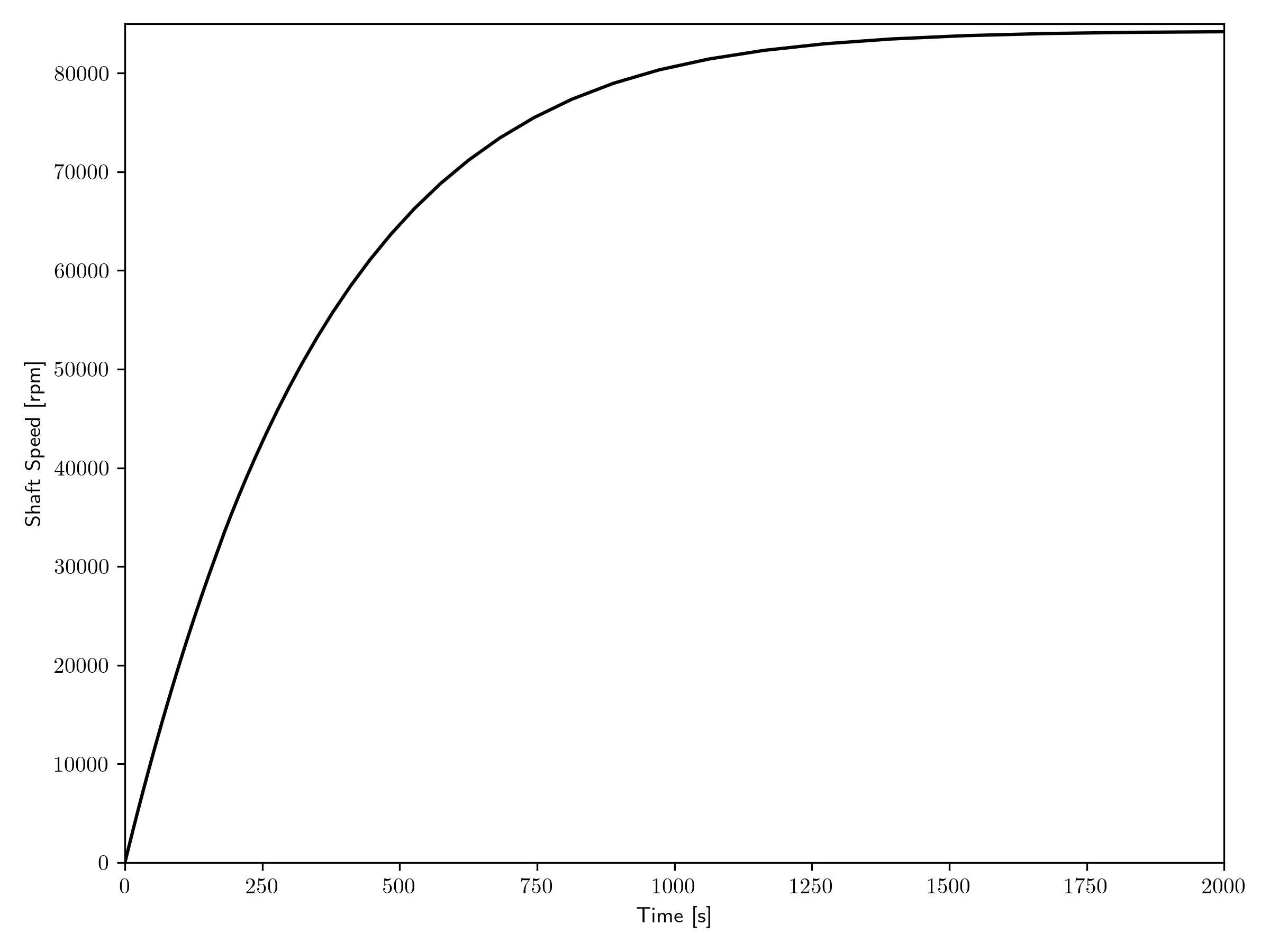
Figure 2: PID start-up of shaft system.
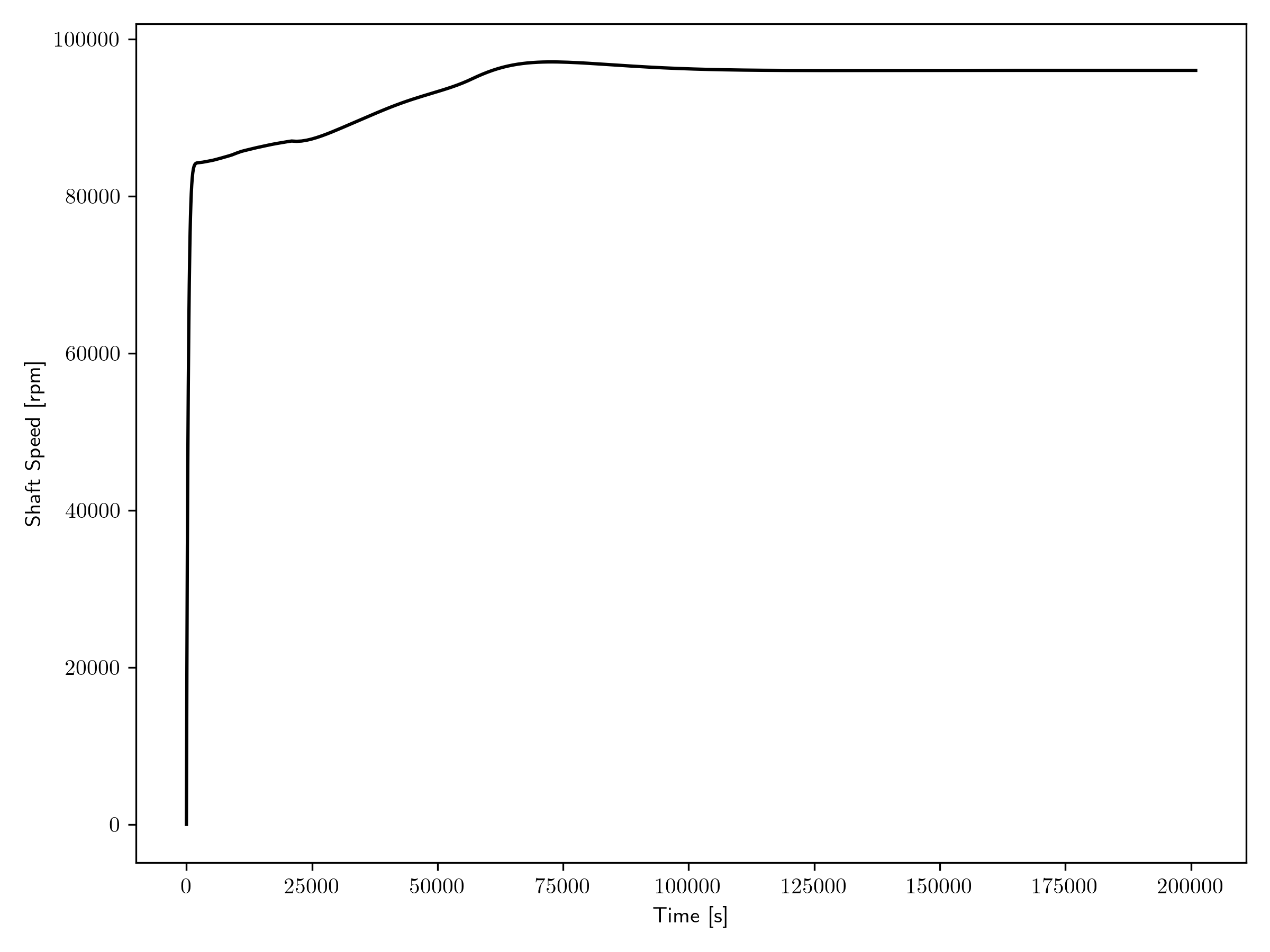
Figure 3: Shaft speed during transient.
As shown in Figure 3, shaft speed is quickly ramped up by the PID and then linearly increases as the working fluid is heated and begins working on the turbine to produce shaft torque. At approximately 20,000 seconds the motor and turbine provide the same amount of torque which initiates the motor shutdown function. A comparison of the motor and turbine torques is shown below in Figure 4.
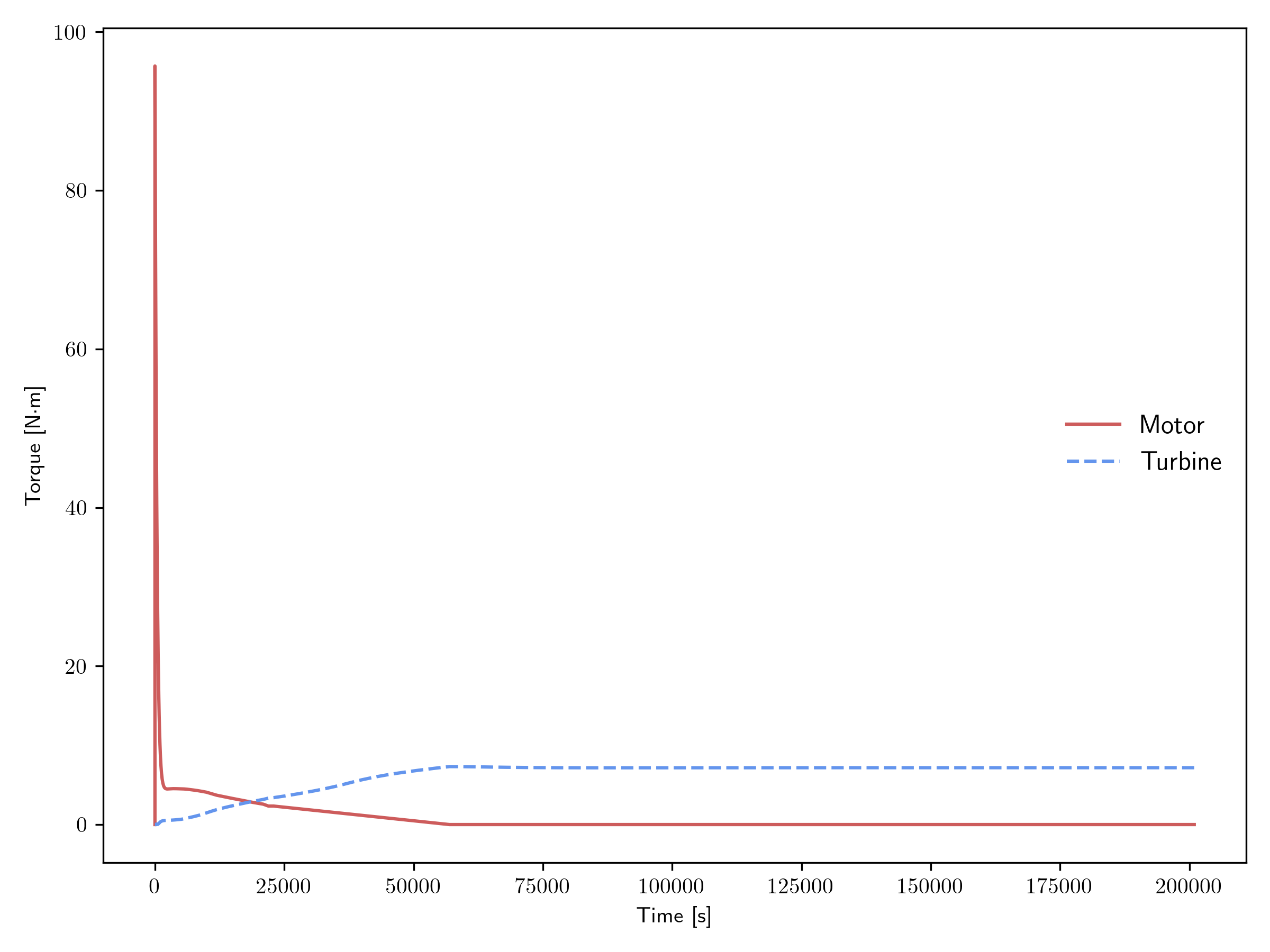
Figure 4: Comparison of the motor and turbine torques.
Figure 5 visualizes the pressure ratios of both the compressor and turbine during the transient. A slight difference is seen between the compressor and turbine steady state pressure ratios due to frictional losses across the piping system and 90° pipe bends, modeled by VolumeJunction1Phase.

Figure 5: Compressor and turbine pressure ratios.
Finally, coolant temperatures across key points of the system are displayed in Figure 6. The reactor inlet and outlet temperatures were omitted as there was no difference between the cold_leg outlet and turbine inlet respectively.
Also, the compressor inlet was not plotted as it remained constant at ambient temperature of 300 K. The compressor outlet temperature sees an immediate increase corresponding to the startup of the PID system while the rest of the temperature responses are dependent upon the heat source power output.
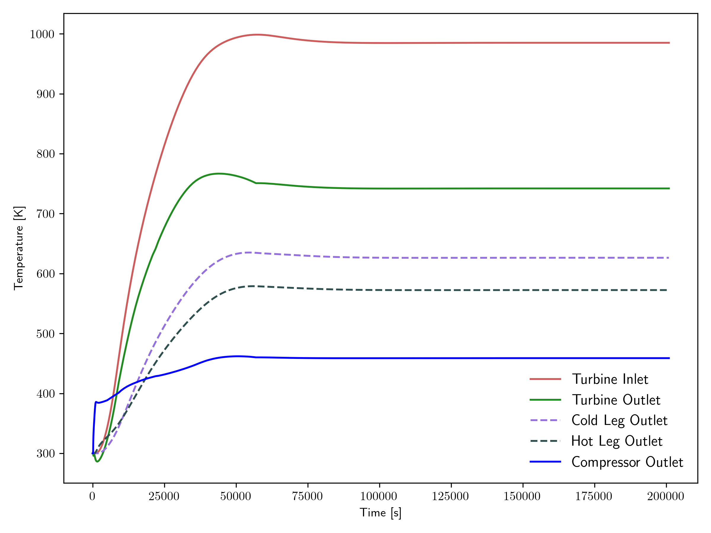
Figure 6: Coolant temperatures across key components.