SCM model for the Pacific Northwest Laboratory's (PNNL) Sleeve Blockage Benchmark
Benchmark Description
PNL's sleeve blockage facility was designed to investigate the turbulent flow phenomena near postulated sleeve blockages in a model nuclear fuel pin bundle. The sleeve blockages were characteristic of fuel-clad swelling or ballooning, which could occur during loss-of-coolant accidents in pressurized-water reactors Creer et al. (1976). The experimental parameters are presented in Table 1.
Table 1: Design and operational parameters for PNL's sleeve blockage benchmark.
| Experiment Parameter (unit) | Value |
|---|---|
| Number of pins (—) | |
| Pin pitch (cm) | |
| Pin diameter (cm) | |
| Length (cm) | |
| Outlet pressure (Pa) | |
| Inlet temperature (K) | |
| Reynolds number (—) | |
| Inlet velocity (m/sec) | |
| Power profile (—) | Uniform zero power |
| Grid spacer location (cm) | |
| Grid spacer loss coefficient (—) | |
| Sleeve blockage location (cm) | (midway between the spacers) |
Sleeve blockages (three inches in length) were positioned on the center nine pins of the bundle. Area reductions, of 70% and 90%, were obtained in the center four subchannels of the bundle. The 70% and 90% blockages corresponded to area reductions of 35% and 45% in the subchannels adjacent to the sides of the cluster and 17% and 22% in the subchannels next to the corners of the blockage, respectively. These area reductions were not intended to define those expected during loss-of-coolant accidents but were chosen to provide a severe test case to verify subchannel computer programs. Axial components of local mean velocity and intensity of turbulence were measured, using a one-velocity component laser Doppler anemometer.
Results
The 70% and 90% blockage was chosen to validate SCM performance. SCM models the blockage by decreasing the surface area of the affected subchannels accordingly. Since the subchannel formulation is based on the concept of the hydraulic diameter, reducing the surface area affects the system of equations in multiple ways. Most significantly through the number and the friction model, pressure drop calculation. Restricting the flow area increases the pressure drop and causes flow to diverge to the adjacent subchannels. Furthermore, the user has the option to apply a concentrated form loss coefficient on the affected subchannels at the corresponding axial cell. This will have an effect similar to the area reduction. SCM was run with 28 axial cells for the 70% blockage case and 84 axial cells for the 90% blockage case. A user-set local form loss coefficient at the blockage, and , was also applied for the two cases, respectively, which was axially distributed among the blocked cells. These values were fitted to produce the best agreement. The default modeling parameters were also used. In addition to SCM, a CFD simulation (Star-CCM+) of the experiment was made with 10.5 million cells, for the 70% blockage case. The results presented in Figure 1 and Figure 2 showcase the relative velocity of a center subchannel across the length of the assembly.
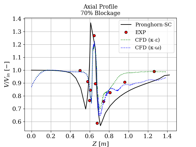
Figure 1: The 70% sleeve blockage.
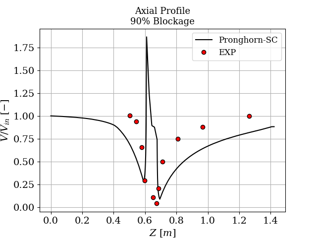
Figure 2: The 90% sleeve blockage.
SCM utilized the implicit monolithic solver, specifically developed to deal with recirculation, as it was the only one that managed to robustly solve the problem. Predicted subchannel average velocities agreed well with measured values for both cases. SCM's predicted flow of a central subchannel over-predicts the mixing length downstream of the blockage and is quicker to reduce upstream of the blockage. One possible explanation of this behavior has to do with the nature of the SCM calculations. Averaged quantities over relatively large volumes are expected to be slower to adapt to local rapid changes. This could also indicate that the inter-channel mixing is underestimated.
For this reason, the SCM imulation was run again, this time with a larger turbulent mixing parameter of and the result is presented in Figure Figure 3. The simulation with the adjusted mixing effect agrees much better with the experimental results, especially downstream of the blockage. This suggests that the calibrated default value of is not general enough to adequately model scenarios where a blockage augments the mixing effects in the wake.
At the exit region of the blockage, the experimental velocity profile obtained with the 70% blockage exhibits a jetting characteristic that was not measured in the 90% blockage case. According to the authors of the experimental analysis Creer et al. (1976), jetting may not have been detected with the 90% blockage because the measuring volume could not be positioned as close to the blockage axial center line as was possible with the 70% blockage. Though it is also probable that no jetting was present due to flow choking. SCM overestimates the jetting effect in both cases.
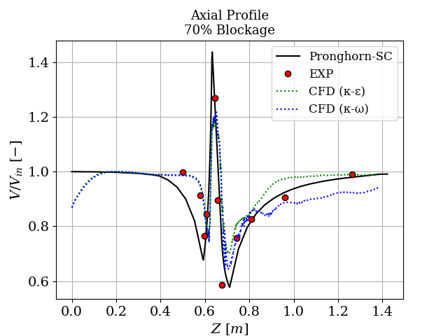
Figure 3: The 70% sleeve blockage with .
It should be noted that the CFD simulation took about 3 hours to converge, while SCM took about 3 seconds. Considering that, along with the agreement of the SCM results with the experimental data, one can say that the SCM is a useful engineering tool for modeling blockage scenarios in square water-cooled assemblies. The effect of the simulated blockage, depends on the axial discretization, flow area reduction and user-defined local form loss coefficient, along with the turbulent modeling parameters. Due to the nonlinear nature of the friction pressure drop calculation, the effect of these parameters is not straightforward and special care must be taken by the user to properly simulate the blockage effects and produce consistent results.
SCM Inputs
The input file to run the 70% blockage case with the improved parameters is presented below:
T_in = 302.594
mass_flux_in = 1730.0950134985335
P_out = 101325 # Pa
# Creer et. al 1976
# Blockage is modeled with area reduction and form loss coefficient distributed on the
# affected subchannels

[QuadSubChannelMesh]
  [sub_channel]
    type = SCMQuadAssemblyMeshGenerator
    nx = 8
    ny = 8
    n_cells = 36
    pitch = 0.0136906
    Kij = 0.5
    pin_diameter = 0.0099568
    side_gap = 0.0036957
    heated_length = 1.4224
    z_blockage = '0.60325 0.67945'
    index_blockage = '18 19 20 21 26 27 28 29 34 35 36 37 42 43 44 45'
    reduction_blockage = '0.83 0.65 0.65 0.83 0.65 0.30 0.30 0.65 0.65 0.30 0.30 0.65 0.83 0.65 0.65 0.83'
    k_blockage = '0.0 0.0 0.0 0.0 0.0 1 1 0.0 0.0 1 1 0.0 0.0 0.0 0.0 0.0'
    spacer_z = '0.3683 1.3843'
    spacer_k = '1.14 1.14'
  []
[]

[AuxVariables<<<{"href": "../../../syntax/AuxVariables/index.html"}>>>]
  [mdot]
    block = subchannel
  []
  [SumWij]
    block = subchannel
  []
  [P]
    block = subchannel
  []
  [DP]
    block = subchannel
  []
  [h]
    block = subchannel
  []
  [T]
    block = subchannel
  []
  [rho]
    block = subchannel
  []
  [mu]
    block = subchannel
  []
  [S]
    block = subchannel
  []
  [w_perim]
    block = subchannel
  []
[]

[FluidProperties<<<{"href": "../../../syntax/FluidProperties/index.html"}>>>]
  [water]
    type = Water97FluidProperties<<<{"description": "Fluid properties for water and steam (H2O) using IAPWS-IF97", "href": "../../../source/fluidproperties/Water97FluidProperties.html"}>>>
  []
[]

[SubChannel]
  type = QuadSubChannel1PhaseProblem
  fp = water
  n_blocks = 1
  compute_density = true
  compute_viscosity = true
  compute_power = false
  P_out = ${P_out}
  implicit = true
  segregated = false
  staggered_pressure = false
  interpolation_scheme = 'upwind'
  friction_closure = 'MATRA'
  mixing_closure ='constant_beta'
  pin_HTC_closure = 'Dittus-Boelter'
[]

[SCMClosures<<<{"href": "../../../syntax/SCMClosures/index.html"}>>>]
  [MATRA]
    type = SCMFrictionMATRA<<<{"description": "Class that computes the axial friction factor using the MATRA correlation.", "href": "../../../source/scmclosures/SCMFrictionMATRA.html"}>>>
  []
  [constant_beta]
    type = SCMMixingConstantBeta<<<{"description": "Class that models the turbulent mixing coefficient beta as a user defined constant.", "href": "../../../source/scmclosures/SCMMixingConstantBeta.html"}>>>
    beta<<<{"description": "Turbulent mixing parameter [-]."}>>> = 0.006
    CT<<<{"description": "Turbulent momentum, modeling parameter [-]."}>>> = 2.6
  []
  [Dittus-Boelter]
    type = SCMHTCDittusBoelter<<<{"description": "Class that computes the convective heat transfer coefficient using the Dittus Boelter correlation.", "href": "../../../source/scmclosures/SCMHTCDittusBoelter.html"}>>>
  []
[]

[ICs<<<{"href": "../../../syntax/ICs/index.html"}>>>]

  [q_prime_IC]
    type = SCMQuadPowerIC<<<{"description": "Computes axial heat rate (W/m) assigned to the fuel pins in a square lattice arrangement", "href": "../../../source/ics/SCMQuadPowerIC.html"}>>>
    variable<<<{"description": "The variable this initial condition is supposed to provide values for."}>>> = q_prime
    power<<<{"description": "The postprocessor or Real to use for the total power of the subassembly [W]"}>>> = 0.0 # W
    filename<<<{"description": "name of radial power profile .txt file (should be a single column) [UnitLess]."}>>> = "power_profile.txt"
  []

  [T_ic]
    type = ConstantIC<<<{"description": "Sets a constant field value.", "href": "../../../source/ics/ConstantIC.html"}>>>
    variable<<<{"description": "The variable this initial condition is supposed to provide values for."}>>> = T
    value<<<{"description": "The value to be set in IC"}>>> = ${T_in}
  []

  [P_ic]
    type = ConstantIC<<<{"description": "Sets a constant field value.", "href": "../../../source/ics/ConstantIC.html"}>>>
    variable<<<{"description": "The variable this initial condition is supposed to provide values for."}>>> = P
    value<<<{"description": "The value to be set in IC"}>>> = 0.0
  []

  [DP_ic]
    type = ConstantIC<<<{"description": "Sets a constant field value.", "href": "../../../source/ics/ConstantIC.html"}>>>
    variable<<<{"description": "The variable this initial condition is supposed to provide values for."}>>> = DP
    value<<<{"description": "The value to be set in IC"}>>> = 0.0
  []

  [Viscosity_ic]
    type = ViscosityIC<<<{"description": "Computes viscosity from specified pressure and temperature", "href": "../../../source/ics/ViscosityIC.html"}>>>
    variable<<<{"description": "The variable this initial condition is supposed to provide values for."}>>> = mu
    p<<<{"description": "Pressure [Pa]"}>>> = ${P_out}
    T<<<{"description": "Temperature [K]"}>>> = T
    fp<<<{"description": "Fluid properties user object name"}>>> = water
  []

  [rho_ic]
    type = RhoFromPressureTemperatureIC<<<{"description": "Computes the density from pressure and temperature.", "href": "../../../source/ics/RhoFromPressureTemperatureIC.html"}>>>
    variable<<<{"description": "The variable this initial condition is supposed to provide values for."}>>> = rho
    p<<<{"description": "The pressure [Pa]"}>>> = ${P_out}
    T<<<{"description": "The temperature [K]"}>>> = T
    fp<<<{"description": "The name of fluid properties user object."}>>> = water
  []

  [h_ic]
    type = SpecificEnthalpyFromPressureTemperatureIC<<<{"description": "Computes the specific enthalpy from pressure and temperature.", "href": "../../../source/ics/SpecificEnthalpyFromPressureTemperatureIC.html"}>>>
    variable<<<{"description": "The variable this initial condition is supposed to provide values for."}>>> = h
    p<<<{"description": "The pressure [Pa]"}>>> = ${P_out}
    T<<<{"description": "The temperature [K]"}>>> = T
    fp<<<{"description": "The name of fluid properties user object."}>>> = water
  []

  [mdot_ic]
    type = ConstantIC<<<{"description": "Sets a constant field value.", "href": "../../../source/ics/ConstantIC.html"}>>>
    variable<<<{"description": "The variable this initial condition is supposed to provide values for."}>>> = mdot
    value<<<{"description": "The value to be set in IC"}>>> = 0.0
  []
[]

[AuxKernels<<<{"href": "../../../syntax/AuxKernels/index.html"}>>>]
  [T_in_bc]
    type = ConstantAux<<<{"description": "Creates a constant field in the domain.", "href": "../../../source/auxkernels/ConstantAux.html"}>>>
    variable<<<{"description": "The name of the variable that this object applies to"}>>> = T
    boundary<<<{"description": "The list of boundaries (ids or names) from the mesh where this object applies"}>>> = inlet
    value<<<{"description": "Some constant value that can be read from the input file"}>>> = ${T_in}
    execute_on<<<{"description": "The list of flag(s) indicating when this object should be executed. For a description of each flag, see https://mooseframework.inl.gov/source/interfaces/SetupInterface.html."}>>> = 'timestep_begin'
  []
  [mdot_in_bc]
    type = SCMMassFlowRateAux<<<{"description": "Computes mass flow rate from specified mass flux and subchannel cross-sectional area. Can read either PostprocessorValue or Real", "href": "../../../source/auxkernels/SCMMassFlowRateAux.html"}>>>
    variable<<<{"description": "The name of the variable that this object applies to"}>>> = mdot
    boundary<<<{"description": "The list of boundaries (ids or names) from the mesh where this object applies"}>>> = inlet
    area<<<{"description": "Cross sectional area [m^2]"}>>> = S
    mass_flux<<<{"description": "The postprocessor or Real to use for the value of mass_flux"}>>> = ${mass_flux_in}
    execute_on<<<{"description": "The list of flag(s) indicating when this object should be executed. For a description of each flag, see https://mooseframework.inl.gov/source/interfaces/SetupInterface.html."}>>> = 'timestep_begin'
  []
[]

[Outputs<<<{"href": "../../../syntax/Outputs/index.html"}>>>]
  exodus<<<{"description": "Output the results using the default settings for Exodus output."}>>> = true
[]

[Executioner<<<{"href": "../../../syntax/Executioner/index.html"}>>>]
  type = Steady
[]

[MultiApps<<<{"href": "../../../syntax/MultiApps/index.html"}>>>]
  [viz]
    type = FullSolveMultiApp<<<{"description": "Performs a complete simulation during each execution.", "href": "../../../source/multiapps/FullSolveMultiApp.html"}>>>
    input_files<<<{"description": "The input file for each App.  If this parameter only contains one input file it will be used for all of the Apps.  When using 'positions_from_file' it is also admissable to provide one input_file per file."}>>> = "detailedMesh.i"
    execute_on<<<{"description": "The list of flag(s) indicating when this object should be executed. For a description of each flag, see https://mooseframework.inl.gov/source/interfaces/SetupInterface.html."}>>> = "final"
  []
[]

[Transfers<<<{"href": "../../../syntax/Transfers/index.html"}>>>]
  ###### Transfers to the detailedMesh at the end of the coupled simulations
  [subchannel_transfer]
    type = SCMSolutionTransfer<<<{"description": "Transfers subchannel or pin solutions from a SubChannel mesh onto a visualization mesh.", "href": "../../../source/transfers/SCMSolutionTransfer.html"}>>>
    to_multi_app<<<{"description": "The name of the MultiApp to transfer the data to"}>>> = viz
    variable<<<{"description": "The auxiliary variables to transfer."}>>> = 'mdot SumWij P DP h T rho mu S'
  []
[]The file that creates the detailed mesh that subchannel solution gets projected on is presented below:
[GlobalParams<<<{"href": "../../../syntax/GlobalParams/index.html"}>>>]
    nx = 8
    ny = 8
    n_cells = 36
    pitch = 0.0136906
    pin_diameter = 0.0099568
    side_gap = 0.0036957
    heated_length = 1.4224
  []

  [Mesh<<<{"href": "../../../syntax/Mesh/index.html"}>>>]
    [assembly]
      type = SCMDetailedQuadAssemblyMeshGenerator<<<{"description": "Creates a detailed mesh of subchannels and fuel pins in a square lattice arrangement", "href": "../../../source/meshgenerators/SCMDetailedQuadAssemblyMeshGenerator.html"}>>>
    []
  []

  [AuxVariables<<<{"href": "../../../syntax/AuxVariables/index.html"}>>>]
    [mdot]
      block = subchannel
    []
    [SumWij]
      block = subchannel
    []
    [P]
      block = subchannel
    []
    [DP]
      block = subchannel
    []
    [h]
      block = subchannel
    []
    [T]
      block = subchannel
    []
    [Tpin]
      block = fuel_pins
    []
    [Dpin]
      block = fuel_pins
    []
    [rho]
      block = subchannel
    []
    [mu]
      block = subchannel
    []
    [S]
      block = subchannel
    []
    [w_perim]
      block = subchannel
    []
    [q_prime]
      block = fuel_pins
    []
  []

  [Problem<<<{"href": "../../../syntax/Problem/index.html"}>>>]
    type = NoSolveProblem
  []

  [Outputs<<<{"href": "../../../syntax/Outputs/index.html"}>>>]
    exodus<<<{"description": "Output the results using the default settings for Exodus output."}>>> = true
  []

  [Executioner<<<{"href": "../../../syntax/Executioner/index.html"}>>>]
    type = Steady
[]References
- JM Creer, DS Rowe, JM Bates, and AM Sutey.
Effects of sleeve blockages on axial velocity and intensity of turbulence in an unheated 7 x 7 pin bundle.[pwr].
Technical Report, Battelle Pacific Northwest Labs., Richland, Wash.(USA), 1976.[Export]