Advanced Meshing Examples
After learning about some of the advanced meshing tools, it is useful to see examples of "what's possible". This chapter contains images and small snippet examples of "what's possible".
Possible Advanced Reactor Geometries
This tutorial covers the generation of mostly standard geometries, but many reactor designs involve features which were not covered previously. Using the tools covered in this section, MOOSE can generate quite complex geometries illustrated here. The key mesh generators required are listed briefly.
Molten Salt Reactor Experiment (MSRE) 2D lattice
PolygonConcentricCircleMeshGenerator is utilized for producing circular and triangular-shaped regions within the lattice.
FillBetweenSidesetsGenerator is employed for generating mesh to fill in the regions between the regions generated by PolygonConcentricCircleMeshGenerator.
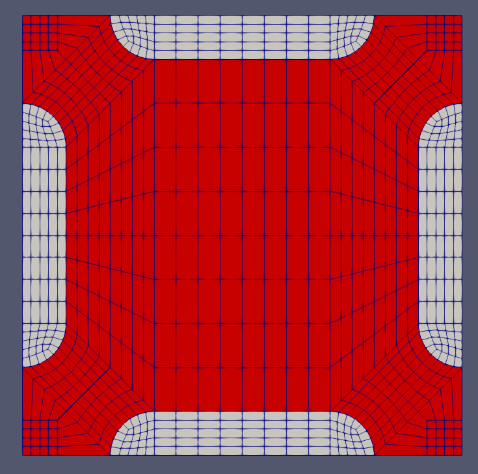
Figure 1: Molten Salt Reactor Experiment (MSRE) 2D lattice.
KRUSTY heat-pipe cooled microreactor 2D core
ParsedCurveGenerator is used for creating the outline of complex shapes before mesh generation.
XYDelaunayGenerator is employed for meshing the irregular areas.
PeripheralTriangleMeshGenerator is utilized to add layers of triangular mesh onto an existing circular mesh.
CircularBoundaryCorrectionGenerator is used to adjust a discretized circle to match the true circle's volume.
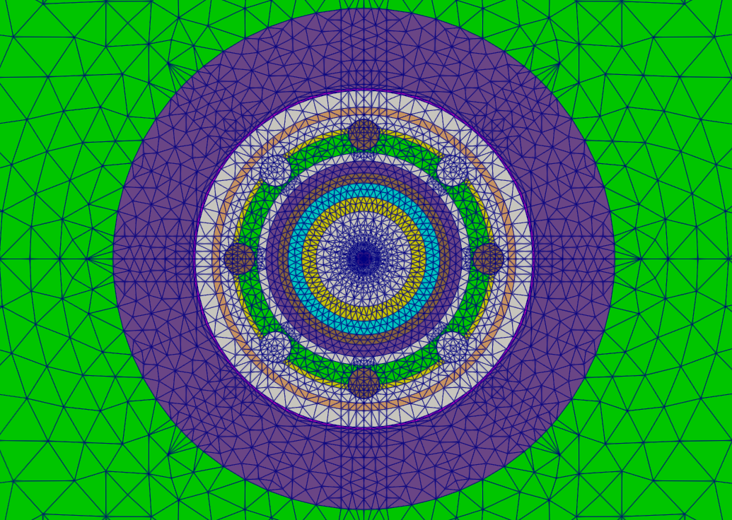
Figure 2: KRUSTY heat pipe-cooled microreactor 2D core.
Modular High Temperature Gas Cooled Reactor (MHTGR)
PolygonConcentricCircleMeshGenerator and PatternedHexMeshGenerator generate pins and assemblies
XYDelaunayGenerator generates control rod holes and reflector assemblies
StitchMeshGenerator merges control rod holes with fuel and reflector assemblies
HexagonConcentricCircleAdaptiveBoundaryMeshGenerator generates ducts for reflector assembly that can be stitched with other assembles.
PatternedHexMeshGenerator generates a lattice of fuel and reflector assemblies into the core
PeripheralRingMeshGenerator adds a circular boundary surrounding the core
AdvancedExtruderGenerator performs 2D to 3D extrusion for the core
DepletionIDGenerator sets up assembly-wise depletion zones
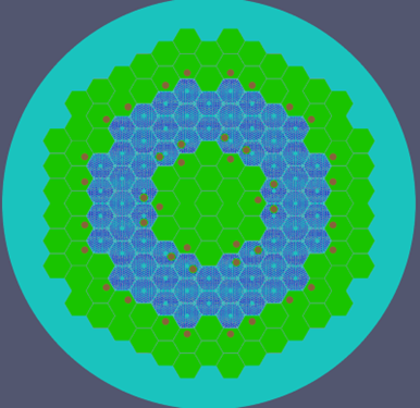
Figure 3: MHTGR 2D mesh.
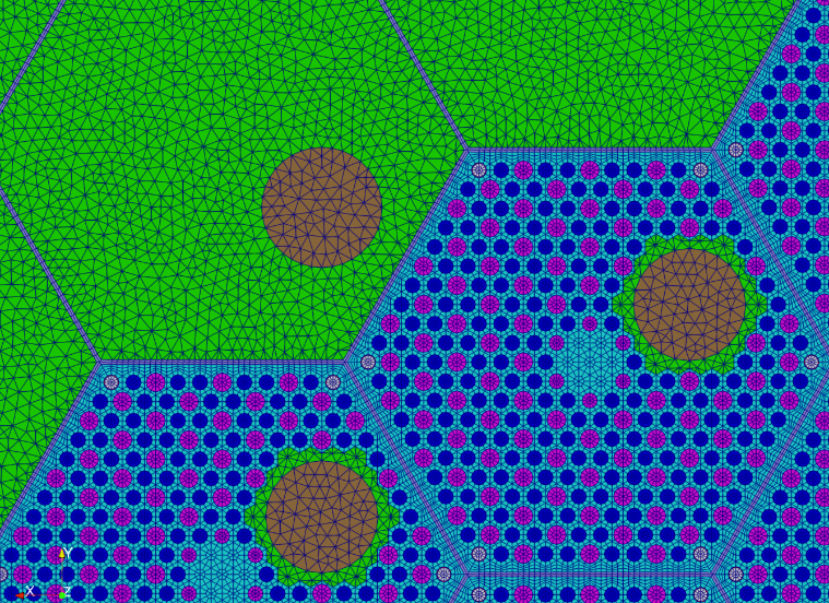
Figure 4: MHTGR 2D mesh, zoomed in.
2D Pebble Bed Reactor with Streamlines
FillBetweenPointVectorsGenerator generates pebble bed streamlines
CartesianMeshGenerator and FillBetweenSidesetsGenerator generates rectangular meshes and trapezoid meshes
StitchMeshGenerator merges core components
CombinerGenerator combines outer walls of core barrel and RPV
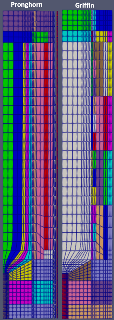
Figure 5: 2D generic pebble bed reactor meshes for Pronghorn (left) and Griffin (right) with flow streamlines from top inlet to bottom conical outlet.
Boundary Layers and Biasing
During the mesh refinement process, it is common to require finer discretizations in one region and coarser discretizations in another region. The boundary layer and biasing features available in the Reactor Module allow the user to refine the mesh in areas of interest for the physics problem at hand.
Mesh Biasing
Mesh biasing applies non-uniform meshing subintervals within a specific region. For example, a fuel pin may generally require an axial meshing size of 5 cm, but at the very top and bottom of the active fuel zone where the power shape has a larger gradient, the user may require finer grids. This is possible using mesh biasing parameters available in AdvancedExtruderGenerator.
![A 3D mesh generated by extruding a 2D square mesh using [AdvancedExtruderGenerator.md] with axial biasing in the top (green) and bottom (white) axial blocks.](../../../large_media/tutorials/tutorial04_meshing/aeg_ax_bias.png)
Figure 6: A 3D mesh generated by extruding a 2D square mesh using AdvancedExtruderGenerator with axial biasing in the top (green) and bottom (white) axial blocks.
Listing 1: Axial mesh biasing example.
[Mesh<<<{"href": "../../../syntax/Mesh/index.html"}>>>]
  [gmg]
    type = GeneratedMeshGenerator<<<{"description": "Create a line, square, or cube mesh with uniformly spaced or biased elements.", "href": "../../../source/meshgenerators/GeneratedMeshGenerator.html"}>>>
    dim<<<{"description": "The dimension of the mesh to be generated"}>>> = 2
    nx<<<{"description": "Number of elements in the X direction"}>>> = 6
    ny<<<{"description": "Number of elements in the Y direction"}>>> = 6
    nz<<<{"description": "Number of elements in the Z direction"}>>> = 0
    zmin<<<{"description": "Lower Z Coordinate of the generated mesh"}>>> = 0
    zmax<<<{"description": "Upper Z Coordinate of the generated mesh"}>>> = 0
    elem_type<<<{"description": "The type of element from libMesh to generate (default: linear element for requested dimension)"}>>> = QUAD4
  []

  [extrude]
    type = AdvancedExtruderGenerator<<<{"description": "Extrudes a 1D mesh into 2D, or a 2D mesh into 3D, and supports a variable height for each elevation, variable number of layers within each elevation, variable growth factors of axial element sizes within each elevation and remap subdomain_ids, boundary_ids and element extra integers within each elevation as well as interface boundaries between neighboring elevation layers, as well as following a 1D curve and modifying the radial (normal to the extrusion axis) extent of the geometry.", "href": "../../../source/meshgenerators/AdvancedExtruderGenerator.html"}>>>
    input<<<{"description": "The mesh to extrude"}>>> = gmg
    heights<<<{"description": "The height of each elevation"}>>> = '2 1 2'
    num_layers<<<{"description": "The number of layers for each elevation - must be num_elevations in length!"}>>> = '5 3 5'
    biases<<<{"description": "The axial growth factor used for mesh biasing for each elevation."}>>> = '1.6 1.0 0.625'
    direction<<<{"description": "A vector that points in the direction to extrude (note, this will be normalized internally - so don't worry about it here)"}>>> = '0 0 1'
    bottom_boundary<<<{"description": "The boundary name to set on the bottom boundary. If omitted an ID will be generated."}>>> = 4
    top_boundary<<<{"description": "The boundary name to set on the top boundary. If omitted an ID will be generated."}>>> = 5
    subdomain_swaps<<<{"description": "For each row, every two entries are interpreted as a pair of 'from' and 'to' to remap the subdomains for that elevation"}>>> = '0 1;
                         0 2;
                         0 3'
  []
[]Similarly, the user may want to radially bias the mesh where solution gradients are known to be high, for example at the edge of a fuel pin or control rod. This is possible using mesh biasing parameters in PolygonConcentricCircleMeshGenerator as well as PeripheralRingMeshGenerator.
![A hexagonal pin mesh generated by [PolygonConcentricCircleMeshGenerator.md] with radial biasing in both the outmost ring block (red) and background block (blue).](../../../large_media/tutorials/tutorial04_meshing/pccmg_rad_bias.png)
Figure 7: A hexagonal pin mesh generated by PolygonConcentricCircleMeshGenerator with radial biasing in both the outmost ring block (red) and background block (blue).
Listing 2: Radial mesh biasing example.
[Mesh<<<{"href": "../../../syntax/Mesh/index.html"}>>>]
  [hex_1]
    type = PolygonConcentricCircleMeshGenerator<<<{"description": "This PolygonConcentricCircleMeshGenerator object is designed to mesh a polygon geometry with optional rings centered inside.", "href": "../../../source/meshgenerators/PolygonConcentricCircleMeshGenerator.html"}>>>
    num_sides<<<{"description": "Number of sides of the polygon."}>>> = 6
    num_sectors_per_side<<<{"description": "Number of azimuthal sectors per polygon side (rotating counterclockwise from top right face)."}>>> = '4 4 4 4 4 4'
    background_intervals<<<{"description": "Number of radial meshing intervals in background region (area between rings and ducts) excluding the background's boundary layers."}>>> = 4
    ring_radii<<<{"description": "Radii of major concentric circles (rings)."}>>> = '2.0 4.0'
    ring_intervals<<<{"description": "Number of radial mesh intervals within each major concentric circle excluding their boundary layers."}>>> = '5 5'
    ring_block_ids<<<{"description": "Optional customized block ids for each ring geometry block."}>>> = '10 11 15'
    ring_block_names<<<{"description": "Optional customized block names for each ring geometry block."}>>> = 'center_tri center mid'
    background_block_ids<<<{"description": "Optional customized block id for the background block."}>>> = 20
    background_block_names<<<{"description": "Optional customized block names for the background block."}>>> = background
    polygon_size<<<{"description": "Size of the polygon to be generated (given as either apothem or radius depending on polygon_size_style)."}>>> = 5.0
    preserve_volumes<<<{"description": "Volume of concentric circles can be preserved using this function."}>>> = on
    ring_radial_biases<<<{"description": "Values used to create biasing in radial meshing for ring regions."}>>> = '1.0 1.6'
    background_radial_bias<<<{"description": "Value used to create biasing in radial meshing for background region."}>>> = 0.625
  []
[]
Figure 8: A peripheral ring mesh with radial biasing added to a hexagonal pin mesh.
Listing 3: Peripheral ring radial mesh biasing example.
[Mesh<<<{"href": "../../../syntax/Mesh/index.html"}>>>]
  [hex_1]
    type = PolygonConcentricCircleMeshGenerator<<<{"description": "This PolygonConcentricCircleMeshGenerator object is designed to mesh a polygon geometry with optional rings centered inside.", "href": "../../../source/meshgenerators/PolygonConcentricCircleMeshGenerator.html"}>>>
    num_sides<<<{"description": "Number of sides of the polygon."}>>> = 6
    num_sectors_per_side<<<{"description": "Number of azimuthal sectors per polygon side (rotating counterclockwise from top right face)."}>>> = '4 4 4 4 4 4'
    background_intervals<<<{"description": "Number of radial meshing intervals in background region (area between rings and ducts) excluding the background's boundary layers."}>>> = 2
    ring_radii<<<{"description": "Radii of major concentric circles (rings)."}>>> = '4.0'
    ring_intervals<<<{"description": "Number of radial mesh intervals within each major concentric circle excluding their boundary layers."}>>> = '2'
    ring_block_ids<<<{"description": "Optional customized block ids for each ring geometry block."}>>> = '10 15'
    ring_block_names<<<{"description": "Optional customized block names for each ring geometry block."}>>> = 'center_tri center'
    background_block_ids<<<{"description": "Optional customized block id for the background block."}>>> = 20
    background_block_names<<<{"description": "Optional customized block names for the background block."}>>> = background
    polygon_size<<<{"description": "Size of the polygon to be generated (given as either apothem or radius depending on polygon_size_style)."}>>> = 5.0
    preserve_volumes<<<{"description": "Volume of concentric circles can be preserved using this function."}>>> = on
    background_radial_bias<<<{"description": "Value used to create biasing in radial meshing for background region."}>>> = 0.625
  []
  [peripheral_ring]
    type = PeripheralRingMeshGenerator<<<{"description": "This PeripheralRingMeshGenerator object adds a circular peripheral region to the input mesh.", "href": "../../../source/meshgenerators/PeripheralRingMeshGenerator.html"}>>>
    input<<<{"description": "The input mesh to be modified."}>>> = hex_1
    peripheral_ring_block_id<<<{"description": "The block id assigned to the created peripheral layer."}>>> = 200
    peripheral_layer_num<<<{"description": "The radial layers of the peripheral ring to be added."}>>> = 5
    input_mesh_external_boundary<<<{"description": "The external boundary of the input mesh."}>>> = 10000
    peripheral_ring_radius<<<{"description": "Radius of the peripheral ring to be added."}>>> = 8
    peripheral_radial_bias<<<{"description": "Value used to create biasing in radial meshing for peripheral ring region."}>>> = 0.625
  []
[]Mesh Boundary Layers
Boundary layers are commonly needed in thermal-hydraulic applications, where the thickness of the mesh near a wall must be a certain size, uniformly, regardless of the width of the meshed region. Boundary layers are possible using PolygonConcentricCircleMeshGenerator and PeripheralRingMeshGenerator.
![A hexagonal pin mesh generated by [PolygonConcentricCircleMeshGenerator.md] with boundary layers created in both the outmost ring block (outer boundary layer, red) and background block (inner boundary layer, blue).](../../../large_media/tutorials/tutorial04_meshing/pccmg_bdry_layer.png)
Figure 9: A hexagonal pin mesh generated by PolygonConcentricCircleMeshGenerator with boundary layers created in both the outmost ring block (outer boundary layer, red) and background block (inner boundary layer, blue).
Listing 4: PolygonConcentricCircleMeshGenerator boundary layer example.
[Mesh<<<{"href": "../../../syntax/Mesh/index.html"}>>>]
  [hex_1]
    type = PolygonConcentricCircleMeshGenerator<<<{"description": "This PolygonConcentricCircleMeshGenerator object is designed to mesh a polygon geometry with optional rings centered inside.", "href": "../../../source/meshgenerators/PolygonConcentricCircleMeshGenerator.html"}>>>
    num_sides<<<{"description": "Number of sides of the polygon."}>>> = 6
    num_sectors_per_side<<<{"description": "Number of azimuthal sectors per polygon side (rotating counterclockwise from top right face)."}>>> = '4 4 4 4 4 4'
    background_intervals<<<{"description": "Number of radial meshing intervals in background region (area between rings and ducts) excluding the background's boundary layers."}>>> = 2
    ring_radii<<<{"description": "Radii of major concentric circles (rings)."}>>> = '2.0 4.0'
    ring_intervals<<<{"description": "Number of radial mesh intervals within each major concentric circle excluding their boundary layers."}>>> = '2 2'
    ring_block_ids<<<{"description": "Optional customized block ids for each ring geometry block."}>>> = '10 11 15'
    ring_block_names<<<{"description": "Optional customized block names for each ring geometry block."}>>> = 'center_tri center mid'
    background_block_ids<<<{"description": "Optional customized block id for the background block."}>>> = 20
    background_block_names<<<{"description": "Optional customized block names for the background block."}>>> = background
    polygon_size<<<{"description": "Size of the polygon to be generated (given as either apothem or radius depending on polygon_size_style)."}>>> = 5.0
    preserve_volumes<<<{"description": "Volume of concentric circles can be preserved using this function."}>>> = on
    ## Background boundary layer setting
    background_inner_boundary_layer_bias<<<{"description": "Growth factor used for mesh biasing of the background inner boundary layer."}>>> = 1.6
    background_inner_boundary_layer_intervals<<<{"description": "Number of radial intervals of the background inner boundary layer"}>>> = 3
    background_inner_boundary_layer_width<<<{"description": "Width of background region that is assigned to be the inner boundary layer."}>>> = 0.4
    ## Ring boundary layer setting
    ring_outer_boundary_layer_biases<<<{"description": "Growth factors used for mesh biasing of the rings' outer boundary layers."}>>> = '1.0 0.625'
    ring_outer_boundary_layer_intervals<<<{"description": "Number of radial intervals of the rings' outer boundary layers"}>>> = '0 3'
    ring_outer_boundary_layer_widths<<<{"description": "Widths of each ring regions that are assigned to be each ring's outer boundary layers."}>>> = '0.0 0.5'
  []
[]Stitching Assemblies with Different Pin Numbers
Typical reactor cores are comprised of many different assembly types, each with different numbers of pins. When the pins are explicitly meshed, the number of nodes on the assembly boundary is determined by a combination of the number pins as well as the pin azimuthal discretization. It is difficult to find a reasonably low azimuthal discretization for each assembly such that all assemblies have the same number of nodes on their boundaries.
The best approach for this situation is to use PatternedHexPeripheralModifier to strip the outermost layer off each assembly and replace it with a transition layer with a set number of nodes on the outermost boundary. Doing this to each assembly will ensure that all assemblies have the same number of boundary nodes and can be easily stitched. An example follows.
![[PatternedHexPeripheralModifier.md] is used to adjust the boundary node count on each assembly to be consistent with each other and therefore stitchable.](../../../large_media/tutorials/tutorial04_meshing/adv_ex_assembies_with_different_pin_nums.png)
Figure 10: PatternedHexPeripheralModifier is used to adjust the boundary node count on each assembly to be consistent with each other and therefore stitchable.
Listing 5: Assemblies with different pin numbers example.
[Mesh<<<{"href": "../../../syntax/Mesh/index.html"}>>>]
  [hex_1]
    type = PolygonConcentricCircleMeshGenerator<<<{"description": "This PolygonConcentricCircleMeshGenerator object is designed to mesh a polygon geometry with optional rings centered inside.", "href": "../../../source/meshgenerators/PolygonConcentricCircleMeshGenerator.html"}>>>
    num_sides<<<{"description": "Number of sides of the polygon."}>>> = 6
    num_sectors_per_side<<<{"description": "Number of azimuthal sectors per polygon side (rotating counterclockwise from top right face)."}>>> = '2 2 2 2 2 2'
    background_intervals<<<{"description": "Number of radial meshing intervals in background region (area between rings and ducts) excluding the background's boundary layers."}>>> = 1
    ring_radii<<<{"description": "Radii of major concentric circles (rings)."}>>> = 4.0
    ring_intervals<<<{"description": "Number of radial mesh intervals within each major concentric circle excluding their boundary layers."}>>> = 1
    ring_block_ids<<<{"description": "Optional customized block ids for each ring geometry block."}>>> = '10'
    ring_block_names<<<{"description": "Optional customized block names for each ring geometry block."}>>> = 'center_1'
    background_block_ids<<<{"description": "Optional customized block id for the background block."}>>> = 20
    background_block_names<<<{"description": "Optional customized block names for the background block."}>>> = background_1
    polygon_size<<<{"description": "Size of the polygon to be generated (given as either apothem or radius depending on polygon_size_style)."}>>> = 5.0
    preserve_volumes<<<{"description": "Volume of concentric circles can be preserved using this function."}>>> = on
    quad_center_elements<<<{"description": "Whether the center elements are quad or triangular."}>>> = true
  []
  [pattern_1]
    type = PatternedHexMeshGenerator<<<{"description": "This PatternedHexMeshGenerator source code assembles hexagonal meshes into a hexagonal grid and optionally forces the outer boundary to be hexagonal and/or adds a duct.", "href": "../../../source/meshgenerators/PatternedHexMeshGenerator.html"}>>>
    inputs<<<{"description": "The input MeshGenerators."}>>> = 'hex_1'
    pattern<<<{"description": "A double-indexed hexagonal-shaped array starting with the upper-left corner."}>>> = '0 0;
              0 0 0;
               0 0'
    background_intervals<<<{"description": "Radial intervals in the assembly peripheral region."}>>> = 1
    hexagon_size<<<{"description": "Size of the outmost hexagon boundary to be generated; this is required only when pattern type is 'hexagon'."}>>> = 17
    #duct_sizes = '15 15.5'
    #duct_intervals = '1 2'
  []
  [pmg_1]
    type = PatternedHexPeripheralModifier<<<{"description": "PatternedPolygonPeripheralModifierBase is the base class for PatternedCartPeripheralModifier and PatternedHexPeripheralModifier.", "href": "../../../source/meshgenerators/PatternedHexPeripheralModifier.html"}>>>
    input<<<{"description": "The input mesh to be modified. Note that this generator only works with PatternedHex/CartesianMeshGenerator and its derived classes such as HexIDPatternedMeshGenerator."}>>> = pattern_1
    input_mesh_external_boundary<<<{"description": "The external boundary of the input mesh."}>>> = 10000
    new_num_sector<<<{"description": "Number of sectors of each side for the new mesh."}>>> = ${new_num_sector}
    num_layers<<<{"description": "Layers of elements for transition."}>>> = ${num_layer}
  []
  [hex_2]
    type = PolygonConcentricCircleMeshGenerator<<<{"description": "This PolygonConcentricCircleMeshGenerator object is designed to mesh a polygon geometry with optional rings centered inside.", "href": "../../../source/meshgenerators/PolygonConcentricCircleMeshGenerator.html"}>>>
    num_sides<<<{"description": "Number of sides of the polygon."}>>> = 6
    num_sectors_per_side<<<{"description": "Number of azimuthal sectors per polygon side (rotating counterclockwise from top right face)."}>>> = '2 2 2 2 2 2'
    background_intervals<<<{"description": "Number of radial meshing intervals in background region (area between rings and ducts) excluding the background's boundary layers."}>>> = 1
    ring_radii<<<{"description": "Radii of major concentric circles (rings)."}>>> = 2.5
    ring_intervals<<<{"description": "Number of radial mesh intervals within each major concentric circle excluding their boundary layers."}>>> = 1
    ring_block_ids<<<{"description": "Optional customized block ids for each ring geometry block."}>>> = '30'
    ring_block_names<<<{"description": "Optional customized block names for each ring geometry block."}>>> = 'center_2'
    background_block_ids<<<{"description": "Optional customized block id for the background block."}>>> = 40
    background_block_names<<<{"description": "Optional customized block names for the background block."}>>> = background_2
    polygon_size<<<{"description": "Size of the polygon to be generated (given as either apothem or radius depending on polygon_size_style)."}>>> = 3.0
    preserve_volumes<<<{"description": "Volume of concentric circles can be preserved using this function."}>>> = on
    quad_center_elements<<<{"description": "Whether the center elements are quad or triangular."}>>> = true
  []
  [pattern_2]
    type = PatternedHexMeshGenerator<<<{"description": "This PatternedHexMeshGenerator source code assembles hexagonal meshes into a hexagonal grid and optionally forces the outer boundary to be hexagonal and/or adds a duct.", "href": "../../../source/meshgenerators/PatternedHexMeshGenerator.html"}>>>
    inputs<<<{"description": "The input MeshGenerators."}>>> = 'hex_2'
    pattern<<<{"description": "A double-indexed hexagonal-shaped array starting with the upper-left corner."}>>> = '0 0 0;
              0 0 0 0;
             0 0 0 0 0;
              0 0 0 0;
               0 0 0'
    background_intervals<<<{"description": "Radial intervals in the assembly peripheral region."}>>> = 1
    hexagon_size<<<{"description": "Size of the outmost hexagon boundary to be generated; this is required only when pattern type is 'hexagon'."}>>> = 17
    #duct_sizes = '15 15.5'
    #duct_intervals = '1 2'
  []
  [pmg_2]
    type = PatternedHexPeripheralModifier<<<{"description": "PatternedPolygonPeripheralModifierBase is the base class for PatternedCartPeripheralModifier and PatternedHexPeripheralModifier.", "href": "../../../source/meshgenerators/PatternedHexPeripheralModifier.html"}>>>
    input<<<{"description": "The input mesh to be modified. Note that this generator only works with PatternedHex/CartesianMeshGenerator and its derived classes such as HexIDPatternedMeshGenerator."}>>> = pattern_2
    input_mesh_external_boundary<<<{"description": "The external boundary of the input mesh."}>>> = 10000
    new_num_sector<<<{"description": "Number of sectors of each side for the new mesh."}>>> = ${new_num_sector}
    num_layers<<<{"description": "Layers of elements for transition."}>>> = ${num_layer}
  []
  [hex_3]
    type = PolygonConcentricCircleMeshGenerator<<<{"description": "This PolygonConcentricCircleMeshGenerator object is designed to mesh a polygon geometry with optional rings centered inside.", "href": "../../../source/meshgenerators/PolygonConcentricCircleMeshGenerator.html"}>>>
    num_sides<<<{"description": "Number of sides of the polygon."}>>> = 6
    num_sectors_per_side<<<{"description": "Number of azimuthal sectors per polygon side (rotating counterclockwise from top right face)."}>>> = '2 2 2 2 2 2'
    background_intervals<<<{"description": "Number of radial meshing intervals in background region (area between rings and ducts) excluding the background's boundary layers."}>>> = 1
    ring_radii<<<{"description": "Radii of major concentric circles (rings)."}>>> = 1.5
    ring_intervals<<<{"description": "Number of radial mesh intervals within each major concentric circle excluding their boundary layers."}>>> = 1
    ring_block_ids<<<{"description": "Optional customized block ids for each ring geometry block."}>>> = '50'
    ring_block_names<<<{"description": "Optional customized block names for each ring geometry block."}>>> = 'center_3'
    background_block_ids<<<{"description": "Optional customized block id for the background block."}>>> = 60
    background_block_names<<<{"description": "Optional customized block names for the background block."}>>> = background_3
    polygon_size<<<{"description": "Size of the polygon to be generated (given as either apothem or radius depending on polygon_size_style)."}>>> = 2.3
    preserve_volumes<<<{"description": "Volume of concentric circles can be preserved using this function."}>>> = on
    quad_center_elements<<<{"description": "Whether the center elements are quad or triangular."}>>> = true
  []
  [pattern_3]
    type = PatternedHexMeshGenerator<<<{"description": "This PatternedHexMeshGenerator source code assembles hexagonal meshes into a hexagonal grid and optionally forces the outer boundary to be hexagonal and/or adds a duct.", "href": "../../../source/meshgenerators/PatternedHexMeshGenerator.html"}>>>
    inputs<<<{"description": "The input MeshGenerators."}>>> = 'hex_3'
    pattern<<<{"description": "A double-indexed hexagonal-shaped array starting with the upper-left corner."}>>> = '0 0 0 0;
              0 0 0 0 0;
             0 0 0 0 0 0;
            0 0 0 0 0 0 0;
             0 0 0 0 0 0;
              0 0 0 0 0;
               0 0 0 0'
    background_intervals<<<{"description": "Radial intervals in the assembly peripheral region."}>>> = 1
    hexagon_size<<<{"description": "Size of the outmost hexagon boundary to be generated; this is required only when pattern type is 'hexagon'."}>>> = 17
    #duct_sizes = '15 15.5'
    #duct_intervals = '1 2'
  []
  [pmg_3]
    type = PatternedHexPeripheralModifier<<<{"description": "PatternedPolygonPeripheralModifierBase is the base class for PatternedCartPeripheralModifier and PatternedHexPeripheralModifier.", "href": "../../../source/meshgenerators/PatternedHexPeripheralModifier.html"}>>>
    input<<<{"description": "The input mesh to be modified. Note that this generator only works with PatternedHex/CartesianMeshGenerator and its derived classes such as HexIDPatternedMeshGenerator."}>>> = pattern_3
    input_mesh_external_boundary<<<{"description": "The external boundary of the input mesh."}>>> = 10000
    new_num_sector<<<{"description": "Number of sectors of each side for the new mesh."}>>> = ${new_num_sector}
    num_layers<<<{"description": "Layers of elements for transition."}>>> = ${num_layer}
  []
  [hex_4]
    type = PolygonConcentricCircleMeshGenerator<<<{"description": "This PolygonConcentricCircleMeshGenerator object is designed to mesh a polygon geometry with optional rings centered inside.", "href": "../../../source/meshgenerators/PolygonConcentricCircleMeshGenerator.html"}>>>
    num_sides<<<{"description": "Number of sides of the polygon."}>>> = 6
    num_sectors_per_side<<<{"description": "Number of azimuthal sectors per polygon side (rotating counterclockwise from top right face)."}>>> = '2 2 2 2 2 2'
    background_intervals<<<{"description": "Number of radial meshing intervals in background region (area between rings and ducts) excluding the background's boundary layers."}>>> = 1
    ring_radii<<<{"description": "Radii of major concentric circles (rings)."}>>> = 1.4
    ring_intervals<<<{"description": "Number of radial mesh intervals within each major concentric circle excluding their boundary layers."}>>> = 1
    ring_block_ids<<<{"description": "Optional customized block ids for each ring geometry block."}>>> = '70'
    ring_block_names<<<{"description": "Optional customized block names for each ring geometry block."}>>> = 'center_4'
    background_block_ids<<<{"description": "Optional customized block id for the background block."}>>> = 80
    background_block_names<<<{"description": "Optional customized block names for the background block."}>>> = background_4
    polygon_size<<<{"description": "Size of the polygon to be generated (given as either apothem or radius depending on polygon_size_style)."}>>> = 1.8
    preserve_volumes<<<{"description": "Volume of concentric circles can be preserved using this function."}>>> = on
    quad_center_elements<<<{"description": "Whether the center elements are quad or triangular."}>>> = true
  []
  [pattern_4]
    type = PatternedHexMeshGenerator<<<{"description": "This PatternedHexMeshGenerator source code assembles hexagonal meshes into a hexagonal grid and optionally forces the outer boundary to be hexagonal and/or adds a duct.", "href": "../../../source/meshgenerators/PatternedHexMeshGenerator.html"}>>>
    inputs<<<{"description": "The input MeshGenerators."}>>> = 'hex_4'
    pattern<<<{"description": "A double-indexed hexagonal-shaped array starting with the upper-left corner."}>>> = '0 0 0 0 0;
              0 0 0 0 0 0;
             0 0 0 0 0 0 0;
            0 0 0 0 0 0 0 0;
           0 0 0 0 0 0 0 0 0;
            0 0 0 0 0 0 0 0;
             0 0 0 0 0 0 0;
              0 0 0 0 0 0;
               0 0 0 0 0'
    background_intervals<<<{"description": "Radial intervals in the assembly peripheral region."}>>> = 1
    hexagon_size<<<{"description": "Size of the outmost hexagon boundary to be generated; this is required only when pattern type is 'hexagon'."}>>> = 17
    #duct_sizes = '15 15.5'
    #duct_intervals = '1 2'
  []
  [pmg_4]
    type = PatternedHexPeripheralModifier<<<{"description": "PatternedPolygonPeripheralModifierBase is the base class for PatternedCartPeripheralModifier and PatternedHexPeripheralModifier.", "href": "../../../source/meshgenerators/PatternedHexPeripheralModifier.html"}>>>
    input<<<{"description": "The input mesh to be modified. Note that this generator only works with PatternedHex/CartesianMeshGenerator and its derived classes such as HexIDPatternedMeshGenerator."}>>> = pattern_4
    input_mesh_external_boundary<<<{"description": "The external boundary of the input mesh."}>>> = 10000
    new_num_sector<<<{"description": "Number of sectors of each side for the new mesh."}>>> = ${new_num_sector}
    num_layers<<<{"description": "Layers of elements for transition."}>>> = ${num_layer}
  []
  [pattern_sum]
    type = PatternedHexMeshGenerator<<<{"description": "This PatternedHexMeshGenerator source code assembles hexagonal meshes into a hexagonal grid and optionally forces the outer boundary to be hexagonal and/or adds a duct.", "href": "../../../source/meshgenerators/PatternedHexMeshGenerator.html"}>>>
    inputs<<<{"description": "The input MeshGenerators."}>>> = 'pmg_1 pmg_2 pmg_3 pmg_4'
    pattern<<<{"description": "A double-indexed hexagonal-shaped array starting with the upper-left corner."}>>> = '2 3;
              1 0 1;
               3 2'
    pattern_boundary<<<{"description": "The boundary shape of the patterned mesh."}>>> = none
    generate_core_metadata<<<{"description": "A Boolean parameter that controls whether the core related metadata is generated for other MOOSE objects such as 'MultiControlDrumFunction' or not."}>>> = true
  []
[]Oversized Pin
Some assemblies contain an oversized pin which intrudes on neighboring unit pin cells. Here, we describe one possible approach to mesh this situation.
First, define the regular small fuel pins and place them into the assembly as a full lattice. Next, delete the dummy unit pin cells, making sure to assign the newly created hole boundary a specific boundary name.
Separately, the oversized pin should be defined as its own object, remembering to remove the background region which is created by default in PolygonConcentricCircleMeshGenerator. This mesh will serve as the "hole" for XYDelaunayGenerator.
Finally, XYDelaunayGenerator is used to mesh the regions between the assembly (with deleted dummies) and the oversized pin. This is done by giving XYDelaunayGenerator the assembly mesh and the oversized pin mesh and specifying via input parameters that the region between the assembly mesh and the oversized pin mesh should be triangulated. The oversized pin mesh is placed into the geometry at this time as well.
![An assembly mesh with an oversized pin in the center. The mesh is generated by modifying the output of [PatternedHexMeshGenerator.md] by replacing the central region with a mesh generated by [XYDelaunayGenerator.md].](../../../large_media/tutorials/tutorial04_meshing/adv_ex_oversized_pin.png)
Figure 11: An assembly mesh with an oversized pin in the center. The mesh is generated by modifying the output of PatternedHexMeshGenerator by replacing the central region with a mesh generated by XYDelaunayGenerator.
Listing 6: Oversized pin example.
[Mesh<<<{"href": "../../../syntax/Mesh/index.html"}>>>]
  [pin_regular]
    type = AdvancedConcentricCircleGenerator<<<{"description": "This AdvancedConcentricCircleGenerator object is designed to mesh a concentric circular geometry.", "href": "../../../source/meshgenerators/AdvancedConcentricCircleGenerator.html"}>>>
    num_sectors<<<{"description": "Number of azimuthal sectors of the circular mesh to be generated."}>>> = 12
    ring_radii<<<{"description": "Radii of major concentric circles (rings)."}>>> = '1 2'
    ring_intervals<<<{"description": "Number of radial mesh intervals within each major concentric circle excluding their boundary layers."}>>> = '2 2'
    ring_block_ids<<<{"description": "Optional customized block ids for each ring geometry block."}>>> = '10 15 20'
    ring_block_names<<<{"description": "Optional customized block names for each ring geometry block."}>>> = 'inner_tri inner outer'
    external_boundary_id<<<{"description": "Optional customized external boundary id."}>>> = 100
    external_boundary_name<<<{"description": "Optional customized external boundary name."}>>> = 'ext'
    create_outward_interface_boundaries<<<{"description": "Whether the outward interface boundaries are created."}>>> = false
  []
  [pin_oversize]
    type = AdvancedConcentricCircleGenerator<<<{"description": "This AdvancedConcentricCircleGenerator object is designed to mesh a concentric circular geometry.", "href": "../../../source/meshgenerators/AdvancedConcentricCircleGenerator.html"}>>>
    num_sectors<<<{"description": "Number of azimuthal sectors of the circular mesh to be generated."}>>> = 12
    ring_radii<<<{"description": "Radii of major concentric circles (rings)."}>>> = '2 3'
    ring_intervals<<<{"description": "Number of radial mesh intervals within each major concentric circle excluding their boundary layers."}>>> = '2 2'
    ring_block_ids<<<{"description": "Optional customized block ids for each ring geometry block."}>>> = '30 35 40'
    ring_block_names<<<{"description": "Optional customized block names for each ring geometry block."}>>> = 'inner_os_tri inner_os outer_os'
    external_boundary_id<<<{"description": "Optional customized external boundary id."}>>> = 100
    external_boundary_name<<<{"description": "Optional customized external boundary name."}>>> = 'ext'
    create_outward_interface_boundaries<<<{"description": "Whether the outward interface boundaries are created."}>>> = false
  []
  [fpg]
    type = FlexiblePatternGenerator<<<{"description": "This FlexiblePatternGenerator object is designed to generate a mesh with a background region with dispersed unit meshes in it and distributed based on a series of flexible patterns.", "href": "../../../source/meshgenerators/FlexiblePatternGenerator.html"}>>>
    inputs<<<{"description": "The input MeshGenerators."}>>> = 'pin_regular pin_oversize'
    boundary_type<<<{"description": "what type of boundary is used as background for patterning."}>>> = HEXAGON
    boundary_sectors<<<{"description": "The number of sectors on each side of the HEXAGON or CARTESIAN boundary mesh or on the circular boundary of the CIRCLE boundary mesh."}>>> = 10
    boundary_size<<<{"description": "The pitch size of the HEXAGON or CARTESIAN boundary mesh; or the diameter of the CIRCLE boundary mesh."}>>> = '${fparse 22.0*sqrt(3.0)}'
    hex_patterns<<<{"description": "Hexagonal patterns set."}>>> = '0 0 0 0;
                   0 1 0 1 0;
                  0 0 0 0 0 0;
                 0 0 0 1 0 0 0;
                  0 0 0 0 0 0;
                   0 1 0 1 0;
                    0 0 0 0'
    hex_pitches<<<{"description": "pitch sizes used to generate the hexagonal patterns."}>>> = '5.5'
    hex_origins<<<{"description": "the origin positions of the hexagonal patterns,"}>>> = '0.0 0.0 0.0'
    use_auto_area_func<<<{"description": "Use the automatic area function for triangle-meshing in the background."}>>> = true
  []
[]Filling Between Curves using "FillBetweenSidesetsGenerator"
The MSRE 2D lattice case pictured in tutorial04-adv_ex_fbsg was constructed using the FillBetweenSidesetsGenerator to connect "quarter" circular pins, as shown in tutorial04-adv_ex_fbsg. First, ConcentricCircleMeshGenerator (a predecessor of PolygonConcentricCircleMeshGenerator which has a different set of input options and works only for square pin cells) was used to create two quarter pins. Each quarter pin mesh initially contains two duplicate "quarter pin" shaped blocks, and then one of the duplicate blocks is deleted in order to be able to label the sideset on the curved boundary as curve_1 and curve_2 in the two pins, respectively. This is the simplest possible procedure with the current Mesh system in MOOSE, but could be improved in the future. These two pins were translated in space to move them apart from each other, and then FillBetweenSidesetsGenerator was used to mesh the area between curve_1 and curve_2.
![An example of using [FillBetweenSidesetsGenerator.md] to connect quarter circular-shapedsquare meshes.](../../../large_media/tutorials/tutorial04_meshing/adv_ex_fbsg.png)
Figure 12: An example of using FillBetweenSidesetsGenerator to connect quarter circular-shapedsquare meshes.
Listing 7: FillBetweenSidesetsGenerator example.
[Mesh<<<{"href": "../../../syntax/Mesh/index.html"}>>>]
  [connect_two_circles]
    type = FillBetweenSidesetsGenerator<<<{"description": "This FillBetweenSidesetsGenerator object is designed to generate a transition layer to connect two boundaries of two input meshes.", "href": "../../../source/meshgenerators/FillBetweenSidesetsGenerator.html"}>>>
    input_mesh_1<<<{"description": "The input mesh that contains boundary_1"}>>> = 'Corner_bottom_left_2'
    input_mesh_2<<<{"description": "The input mesh that contains boundary_2"}>>> = 'Corner_top_right_3'
    boundary_1<<<{"description": "the first boundary that needs to be connected."}>>> = 'curve_1'
    boundary_2<<<{"description": "the second boundary that needs to be connected."}>>> = 'curve_2'
    num_layers<<<{"description": "Number of layers of elements created between the boundaries."}>>> = 8
    keep_inputs<<<{"description": "Whether to output the input meshes stitched with the transition layer connector."}>>> = true
    use_quad_elements<<<{"description": "Whether QUAD4 instead of TRI3 elements are used to construct the transition layer."}>>> = true
    block_id<<<{"description": "ID to be assigned to the transition layer."}>>> = 200
  []
[]Triangulation of Odd-Shaped Regions Using "ParsedCurveGenerator" and "XYDelaunayGenerator"
This example demonstrates how to place a control drum object in an arbitrary position in a core that may overlap subdomain boundaries.
First, the center assembly is created using regular pins and procedures.
![An example of using [XYDelaunayGenerator.md] with curve meshes generated by [ParsedCurveGenerator.md], patterned pins.](../../../large_media/tutorials/tutorial04_meshing/adv_ex_pcg_xy_patterned_pins.png)
Figure 13: An example of using XYDelaunayGenerator with curve meshes generated by ParsedCurveGenerator, patterned pins.
Listing 8: An example of using XYDelaunayGenerator with curve meshes generated by ParsedCurveGenerator, patterned pins.
[Mesh<<<{"href": "../../../syntax/Mesh/index.html"}>>>]
  [hex_1]
    type = PolygonConcentricCircleMeshGenerator<<<{"description": "This PolygonConcentricCircleMeshGenerator object is designed to mesh a polygon geometry with optional rings centered inside.", "href": "../../../source/meshgenerators/PolygonConcentricCircleMeshGenerator.html"}>>>
    num_sides<<<{"description": "Number of sides of the polygon."}>>> = 6
    num_sectors_per_side<<<{"description": "Number of azimuthal sectors per polygon side (rotating counterclockwise from top right face)."}>>> = '2 2 2 2 2 2'
    background_intervals<<<{"description": "Number of radial meshing intervals in background region (area between rings and ducts) excluding the background's boundary layers."}>>> = 2
    ring_radii<<<{"description": "Radii of major concentric circles (rings)."}>>> = 4.0
    ring_intervals<<<{"description": "Number of radial mesh intervals within each major concentric circle excluding their boundary layers."}>>> = 2
    ring_block_ids<<<{"description": "Optional customized block ids for each ring geometry block."}>>> = '10 15'
    ring_block_names<<<{"description": "Optional customized block names for each ring geometry block."}>>> = 'pin_tri pin_quad'
    background_block_ids<<<{"description": "Optional customized block id for the background block."}>>> = 20
    background_block_names<<<{"description": "Optional customized block names for the background block."}>>> = pin_background
    polygon_size<<<{"description": "Size of the polygon to be generated (given as either apothem or radius depending on polygon_size_style)."}>>> = 5.0
    preserve_volumes<<<{"description": "Volume of concentric circles can be preserved using this function."}>>> = on
  []

  [pattern]
    type = PatternedHexMeshGenerator<<<{"description": "This PatternedHexMeshGenerator source code assembles hexagonal meshes into a hexagonal grid and optionally forces the outer boundary to be hexagonal and/or adds a duct.", "href": "../../../source/meshgenerators/PatternedHexMeshGenerator.html"}>>>
    inputs<<<{"description": "The input MeshGenerators."}>>> = 'hex_1'
    hexagon_size<<<{"description": "Size of the outmost hexagon boundary to be generated; this is required only when pattern type is 'hexagon'."}>>> = 25
    background_block_id<<<{"description": "Optional customized block id for the background block in 'assembly' mode; must be provided along with 'duct_block_ids' if 'duct_sizes' is provided."}>>> = 30
    background_block_name<<<{"description": "Optional customized block name for the background block in 'assembly' mode; must be provided along with 'duct_block_names' if 'duct_sizes' is provided."}>>> = assembly_background
    pattern<<<{"description": "A double-indexed hexagonal-shaped array starting with the upper-left corner."}>>> = '0 0 0;
                0 0 0 0;
               0 0 0 0 0;
                0 0 0 0;
                 0 0 0'
  []
[]Next, two circular peripheral regions are added using PeripheralTriangleMeshGenerator (yellow, purple zones).
![An example of using [XYDelaunayGenerator.md] with curve meshes generated by [ParsedCurveGenerator.md], patterned pins with rings.](../../../large_media/tutorials/tutorial04_meshing/adv_ex_pcg_xy_patterned_pins_with_rings.png)
Figure 14: An example of using XYDelaunayGenerator with curve meshes generated by ParsedCurveGenerator, patterned pins with rings.
Listing 9: An example of using XYDelaunayGenerator with curve meshes generated by ParsedCurveGenerator, patterned pins with rings.
[Mesh<<<{"href": "../../../syntax/Mesh/index.html"}>>>]
  [tmg1]
    type = PeripheralTriangleMeshGenerator<<<{"description": "This PeripheralTriangleMeshGenerator object is designed to generate a triangulated mesh between a generated outer circle boundary and a provided inner mesh.", "href": "../../../source/meshgenerators/PeripheralTriangleMeshGenerator.html"}>>>
    input<<<{"description": "The input mesh to be modified."}>>> = pattern
    peripheral_ring_radius<<<{"description": "Radius of the peripheral ring to be added."}>>> = 35
    peripheral_ring_num_segments<<<{"description": "Number of segments of the peripheral ring."}>>> = 50
    peripheral_ring_block_name<<<{"description": "The block name assigned to the created peripheral layer."}>>> = peripheral_1
    desired_area<<<{"description": "Desired (maximum) triangle area, or 0 to skip uniform refinement"}>>> = 8
  []

  [tmg2]
    type = PeripheralTriangleMeshGenerator<<<{"description": "This PeripheralTriangleMeshGenerator object is designed to generate a triangulated mesh between a generated outer circle boundary and a provided inner mesh.", "href": "../../../source/meshgenerators/PeripheralTriangleMeshGenerator.html"}>>>
    input<<<{"description": "The input mesh to be modified."}>>> = tmg1
    peripheral_ring_radius<<<{"description": "Radius of the peripheral ring to be added."}>>> = 38
    peripheral_ring_num_segments<<<{"description": "Number of segments of the peripheral ring."}>>> = 80
    peripheral_ring_block_name<<<{"description": "The block name assigned to the created peripheral layer."}>>> = peripheral_2
    desired_area<<<{"description": "Desired (maximum) triangle area, or 0 to skip uniform refinement"}>>> = 6
  []
[]Next, the complex boundary shape which is the outer edge of the light blue zone is defined using ParsedCurveGenerator and analytic piecewise functions. The interior of this boundary is then filled in, including the center assembly, using XYDelaunayGenerator.
![An example of using [XYDelaunayGenerator.md] with curve meshes generated by [ParsedCurveGenerator.md], patterned pins with irregular peripheral region.](../../../large_media/tutorials/tutorial04_meshing/adv_ex_pcg_xy_patterned_pins_with_irregular_peripheral_region.png)
Figure 15: An example of using XYDelaunayGenerator with curve meshes generated by ParsedCurveGenerator, patterned pins with irregular peripheral region.
Listing 10: An example of using XYDelaunayGenerator with curve meshes generated by ParsedCurveGenerator, patterned pins with irregular peripheral region.
[Mesh<<<{"href": "../../../syntax/Mesh/index.html"}>>>]
  [pcg1]
    type = ParsedCurveGenerator<<<{"description": "This ParsedCurveGenerator object is designed to generate a mesh of a curve that consists of EDGE2, EDGE3, or EDGE4 elements.", "href": "../../../source/meshgenerators/ParsedCurveGenerator.html"}>>>
    x_formula<<<{"description": "Function expression of x(t)"}>>> = 't1:=t;
                     t2:=t-1;
                     t3:=t-2;
                     t4:=t-3;
                     x1:=r*cos(t1*(th1-th0)+th0);
                     x2_0:=r*cos(th1);
                     x2_1:=x2_0-Lx;
                     x2:=x2_0+(x2_1-x2_0)*t2;
                     rs:=abs(r*sin(th1));
                     rth0:=1.5*pi;
                     rth1:=0.5*pi;
                     x3:=x2_1+rs*cos(rth0+(rth1-rth0)*t3);
                     x4_1:=r*cos(th1);
                     x4_0:=x4_1-Lx;
                     x4:=x4_0+(x4_1-x4_0)*t4;
                     if(t<1,x1,if(t<2,x2,if(t<3,x3,x4)))'
    y_formula<<<{"description": "Function expression of y(t)"}>>> = 't1:=t;
                     t2:=t-1;
                     t3:=t-2;
                     t4:=t-3;
                     y1:=r*sin(t1*(th1-th0)+th0);
                     y2:=r*sin(th1);
                     rs:=abs(r*sin(th1));
                     rth0:=1.5*pi;
                     rth1:=0.5*pi;
                     y3:=rs*sin(rth0+(rth1-rth0)*t3);
                     y4:=r*sin(th0);
                     if(t<1,y1,if(t<2,y2,if(t<3,y3,y4)))'
    section_bounding_t_values<<<{"description": "The 't' values that bound the sections of the curve. Start and end points must be included. The number of entries in 'nums_segments' should be equal to one less than the number of entries in this parameter."}>>> = '0 1 2 3 4'
    constant_names<<<{"description": "Vector of constants used in the parsed function (use this for kB etc.)"}>>> = 'pi           r    th0               th1                    Lx'
    constant_expressions<<<{"description": "Vector of values for the constants in constant_names (can be an FParser expression)"}>>> = '${fparse pi} 100.0 ${fparse pi/9.0} ${fparse pi/9.0*17.0} 10.0'
    nums_segments<<<{"description": "Numbers of segments (EDGE elements) of each section of the curve to be generated. The number of entries in this parameter should be equal to one less than the number of entries in 'section_bounding_t_values'"}>>> = '50 3 15 3'
    is_closed_loop<<<{"description": "Whether the curve is closed or not."}>>> = true
  []

  [xydg1]
    type = XYDelaunayGenerator<<<{"description": "Triangulates meshes within boundaries defined by input meshes.", "href": "../../../source/meshgenerators/XYDelaunayGenerator.html"}>>>
    boundary<<<{"description": "The input MeshGenerator defining the output outer boundary and required Steiner points."}>>> = 'pcg1'
    holes<<<{"description": "The MeshGenerators that define mesh holes."}>>> = 'tmg2'
    add_nodes_per_boundary_segment<<<{"description": "How many more nodes to add in each outer boundary segment."}>>> = 0
    refine_boundary<<<{"description": "Whether to allow automatically refining the outer boundary."}>>> = false
    desired_area<<<{"description": "Desired (maximum) triangle area, or 0 to skip uniform refinement"}>>> = 30
    output_subdomain_name<<<{"description": "Subdomain name to set on new triangles."}>>> = xy_layer_1
    stitch_holes<<<{"description": "Whether to stitch to the mesh defining each hole."}>>> = 'true'
    refine_holes<<<{"description": "Whether to allow automatically refining each hole boundary."}>>> = 'false'
  []
[]The control drum object is defined including the absorber arc using PolygonConcentricCircleMeshGenerator and AzimuthalBlockSplitGenerator, then the background region of the control drum is deleted to leave only the circular part. This mesh is then translated into the desired position of the final mesh using TransformGenerator. The small red pin is defined similarly (not requiring AzimuthalBlockSplitGenerator).
![An example of using [XYDelaunayGenerator.md] with curve meshes generated by [ParsedCurveGenerator.md], three holes for XYDelaunayGenerator.](../../../large_media/tutorials/tutorial04_meshing/adv_ex_pcg_xy_three_holes_for_xyd.png)
Figure 16: An example of using XYDelaunayGenerator with curve meshes generated by ParsedCurveGenerator, three holes for XYDelaunayGenerator.
Listing 11: An example of using XYDelaunayGenerator with curve meshes generated by ParsedCurveGenerator, three holes for XYDelaunayGenerator.
[Mesh<<<{"href": "../../../syntax/Mesh/index.html"}>>>]
  [cd]
    type = PolygonConcentricCircleMeshGenerator<<<{"description": "This PolygonConcentricCircleMeshGenerator object is designed to mesh a polygon geometry with optional rings centered inside.", "href": "../../../source/meshgenerators/PolygonConcentricCircleMeshGenerator.html"}>>>
    num_sides<<<{"description": "Number of sides of the polygon."}>>> = 6
    num_sectors_per_side<<<{"description": "Number of azimuthal sectors per polygon side (rotating counterclockwise from top right face)."}>>> = '6 6 6 6 6 6'
    background_intervals<<<{"description": "Number of radial meshing intervals in background region (area between rings and ducts) excluding the background's boundary layers."}>>> = 2
    ring_radii<<<{"description": "Radii of major concentric circles (rings)."}>>> = '27 30 32'
    ring_intervals<<<{"description": "Number of radial mesh intervals within each major concentric circle excluding their boundary layers."}>>> = '2 2 2'
    ring_block_ids<<<{"description": "Optional customized block ids for each ring geometry block."}>>> = '110 115 120 125'
    ring_block_names<<<{"description": "Optional customized block names for each ring geometry block."}>>> = 'cd_1_tri cd_1_quad cd_2 cd_3'
    background_block_ids<<<{"description": "Optional customized block id for the background block."}>>> = 130
    background_block_names<<<{"description": "Optional customized block names for the background block."}>>> = cd_background
    polygon_size<<<{"description": "Size of the polygon to be generated (given as either apothem or radius depending on polygon_size_style)."}>>> = 40
    preserve_volumes<<<{"description": "Volume of concentric circles can be preserved using this function."}>>> = on
  []

  [cd_azi_define]
    type = AzimuthalBlockSplitGenerator<<<{"description": "This AzimuthalBlockSplitGenerator object takes in a polygon/hexagon concentric circle mesh and renames blocks on a user-defined azimuthal segment / wedge of the mesh.", "href": "../../../source/meshgenerators/AzimuthalBlockSplitGenerator.html"}>>>
    input<<<{"description": "The input mesh to be modified."}>>> = cd
    start_angle<<<{"description": "Starting azimuthal angle of the new block."}>>> = 300
    angle_range<<<{"description": "Azimuthal angle range of the new block."}>>> = 120
    old_blocks<<<{"description": "The list of blocks in the input mesh that need to be modified."}>>> = '120'
    new_block_ids<<<{"description": "The block IDs to be used for the new selected azimuthal angle blocks."}>>> = '121'
    new_block_names<<<{"description": "The optional block names to be used for the new selected azimulathal angle blocks."}>>> = 'absorber'
    preserve_volumes<<<{"description": "Volume of concentric circles can be preserved using this function."}>>> = true
  []

  [cd_bd]
    type = BlockDeletionGenerator<<<{"description": "Mesh generator which removes elements from the specified subdomains", "href": "../../../source/meshgenerators/BlockDeletionGenerator.html"}>>>
    input<<<{"description": "The mesh we want to modify"}>>> = cd_azi_define
    block<<<{"description": "The list of blocks to be processed (deleted or kept)"}>>> = cd_background
  []

  [cd_translate]
    type = TransformGenerator<<<{"description": "Applies a linear transform to the entire mesh.", "href": "../../../source/meshgenerators/TransformGenerator.html"}>>>
    input<<<{"description": "The mesh we want to modify"}>>> = cd_bd
    transform<<<{"description": "The type of transformation to perform (TRANSLATE, TRANSLATE_CENTER_ORIGIN, TRANSLATE_MIN_ORIGIN, ROTATE, SCALE, ROTATE_WITH_MATRIX, ROTATE_EXT)"}>>> = translate
    vector_value<<<{"description": "The value to use for the transformation. When using TRANSLATE or SCALE, the xyz coordinates are applied in each direction respectively. When using ROTATE, the values are interpreted as the Euler angles phi, theta and psi given in degrees. For ROTATE_EXT, an extrinsic rotation is carried out using prescribed Euler angles alpha, beta, and gamma in degrees."}>>> = '${fparse 100.0*cos(pi/9.0)-10.0} 0 0'
  []

  [outer_pin]
    type = PolygonConcentricCircleMeshGenerator<<<{"description": "This PolygonConcentricCircleMeshGenerator object is designed to mesh a polygon geometry with optional rings centered inside.", "href": "../../../source/meshgenerators/PolygonConcentricCircleMeshGenerator.html"}>>>
    num_sides<<<{"description": "Number of sides of the polygon."}>>> = 6
    num_sectors_per_side<<<{"description": "Number of azimuthal sectors per polygon side (rotating counterclockwise from top right face)."}>>> = '2 2 2 2 2 2'
    background_intervals<<<{"description": "Number of radial meshing intervals in background region (area between rings and ducts) excluding the background's boundary layers."}>>> = 2
    ring_radii<<<{"description": "Radii of major concentric circles (rings)."}>>> = '10 12'
    ring_intervals<<<{"description": "Number of radial mesh intervals within each major concentric circle excluding their boundary layers."}>>> = '2 2'
    ring_block_ids<<<{"description": "Optional customized block ids for each ring geometry block."}>>> = '210 215 220'
    ring_block_names<<<{"description": "Optional customized block names for each ring geometry block."}>>> = 'op_1_tri op_1_quad op_2'
    background_block_ids<<<{"description": "Optional customized block id for the background block."}>>> = 230
    background_block_names<<<{"description": "Optional customized block names for the background block."}>>> = op_background
    polygon_size<<<{"description": "Size of the polygon to be generated (given as either apothem or radius depending on polygon_size_style)."}>>> = 15
    preserve_volumes<<<{"description": "Volume of concentric circles can be preserved using this function."}>>> = on
  []

  [op_bd]
    type = BlockDeletionGenerator<<<{"description": "Mesh generator which removes elements from the specified subdomains", "href": "../../../source/meshgenerators/BlockDeletionGenerator.html"}>>>
    input<<<{"description": "The mesh we want to modify"}>>> = outer_pin
    block<<<{"description": "The list of blocks to be processed (deleted or kept)"}>>> = op_background
  []

  [op_translate]
    type = TransformGenerator<<<{"description": "Applies a linear transform to the entire mesh.", "href": "../../../source/meshgenerators/TransformGenerator.html"}>>>
    input<<<{"description": "The mesh we want to modify"}>>> = op_bd
    transform<<<{"description": "The type of transformation to perform (TRANSLATE, TRANSLATE_CENTER_ORIGIN, TRANSLATE_MIN_ORIGIN, ROTATE, SCALE, ROTATE_WITH_MATRIX, ROTATE_EXT)"}>>> = translate
    vector_value<<<{"description": "The value to use for the transformation. When using TRANSLATE or SCALE, the xyz coordinates are applied in each direction respectively. When using ROTATE, the values are interpreted as the Euler angles phi, theta and psi given in degrees. For ROTATE_EXT, an extrinsic rotation is carried out using prescribed Euler angles alpha, beta, and gamma in degrees."}>>> = '${fparse 120/sqrt(2)} ${fparse 120/sqrt(2)} 0'
  []
[]The outer boundary of the dark blue zone is then generated using ParsedCurveGenerator and analytical functions. XYDelaunayGenerator is again used to fill the dark blue regions, keeping the light blue region and assembly, control drum, and small pin.
![An example of using [XYDelaunayGenerator.md] with curve meshes generated by [ParsedCurveGenerator.md], second XYDelaunayGenerator.](../../../large_media/tutorials/tutorial04_meshing/adv_ex_pcg_xy_second_xyd.png)
Figure 17: An example of using XYDelaunayGenerator with curve meshes generated by ParsedCurveGenerator, second XYDelaunayGenerator.
Listing 12: An example of using XYDelaunayGenerator with curve meshes generated by ParsedCurveGenerator, second XYDelaunayGenerator.
[Mesh<<<{"href": "../../../syntax/Mesh/index.html"}>>>]
  [pcg2]
    type = ParsedCurveGenerator<<<{"description": "This ParsedCurveGenerator object is designed to generate a mesh of a curve that consists of EDGE2, EDGE3, or EDGE4 elements.", "href": "../../../source/meshgenerators/ParsedCurveGenerator.html"}>>>
    x_formula<<<{"description": "Function expression of x(t)"}>>> = 'r*cos(t)'
    y_formula<<<{"description": "Function expression of y(t)"}>>> = 'r*sin(t)'
    section_bounding_t_values<<<{"description": "The 't' values that bound the sections of the curve. Start and end points must be included. The number of entries in 'nums_segments' should be equal to one less than the number of entries in this parameter."}>>> = '0 ${fparse 2*pi}'
    constant_names<<<{"description": "Vector of constants used in the parsed function (use this for kB etc.)"}>>> = 'pi           r'
    constant_expressions<<<{"description": "Vector of values for the constants in constant_names (can be an FParser expression)"}>>> = '${fparse pi} 140.0'
    nums_segments<<<{"description": "Numbers of segments (EDGE elements) of each section of the curve to be generated. The number of entries in this parameter should be equal to one less than the number of entries in 'section_bounding_t_values'"}>>> = '100'
    is_closed_loop<<<{"description": "Whether the curve is closed or not."}>>> = true
  []

  [xydg2]
    type = XYDelaunayGenerator<<<{"description": "Triangulates meshes within boundaries defined by input meshes.", "href": "../../../source/meshgenerators/XYDelaunayGenerator.html"}>>>
    boundary<<<{"description": "The input MeshGenerator defining the output outer boundary and required Steiner points."}>>> = 'pcg2'
    holes<<<{"description": "The MeshGenerators that define mesh holes."}>>> = 'xydg1 cd_translate op_translate'
    add_nodes_per_boundary_segment<<<{"description": "How many more nodes to add in each outer boundary segment."}>>> = 0
    refine_boundary<<<{"description": "Whether to allow automatically refining the outer boundary."}>>> = false
    desired_area<<<{"description": "Desired (maximum) triangle area, or 0 to skip uniform refinement"}>>> = 30
    output_subdomain_name<<<{"description": "Subdomain name to set on new triangles."}>>> = xy_layer_2
    stitch_holes<<<{"description": "Whether to stitch to the mesh defining each hole."}>>> = 'true true true'
    refine_holes<<<{"description": "Whether to allow automatically refining each hole boundary."}>>> = 'false false false'
  []
[]Finally, a circular peripheral region is added at the end using PeripheralTriangleMeshGenerator (yellow).
![An example of using [XYDelaunayGenerator.md] with curve meshes generated by [ParsedCurveGenerator.md], complete.](../../../large_media/tutorials/tutorial04_meshing/adv_ex_pcg_and_xyd.png)
Figure 18: An example of using XYDelaunayGenerator with curve meshes generated by ParsedCurveGenerator, complete.
Listing 13: An example of using XYDelaunayGenerator with curve meshes generated by ParsedCurveGenerator, complete.
[Mesh<<<{"href": "../../../syntax/Mesh/index.html"}>>>]
  [tmg3]
    type = PeripheralTriangleMeshGenerator<<<{"description": "This PeripheralTriangleMeshGenerator object is designed to generate a triangulated mesh between a generated outer circle boundary and a provided inner mesh.", "href": "../../../source/meshgenerators/PeripheralTriangleMeshGenerator.html"}>>>
    input<<<{"description": "The input mesh to be modified."}>>> = xydg2
    peripheral_ring_radius<<<{"description": "Radius of the peripheral ring to be added."}>>> = 150
    peripheral_ring_num_segments<<<{"description": "Number of segments of the peripheral ring."}>>> = 100
    peripheral_ring_block_name<<<{"description": "The block name assigned to the created peripheral layer."}>>> = peripheral_3
    desired_area<<<{"description": "Desired (maximum) triangle area, or 0 to skip uniform refinement"}>>> = 20
  []
[]