Frequently Used Operations and Corresponding MeshGenerators
Mesh Trimming Along Lines of Symmetry
Reactor cores are often designed with lines of symmetry through the core center, which in turn entails a symmetric solution. To save computational resources, the mesh can be cut along lines of symmetry and reflective boundary conditions can be applied to the solution at the cut interface. Through-the-center mesh trimming is required to cut the mesh along these symmetry lines.
An alternative type of symmetry occurs in certain "unit cells" which contain half-pins on the edge of the unit cell. When repeated (mirrored) on the lines of symmetry, these half-pins become full pins and part of a larger core structure. To create these unit cells, an assembly with multiple pins is created (with intact pins), and then peripheral trimming is applied to the assembly along any or all of six possible lines cutting through the outer ring of hexagonal pins.
Object
(Cartesian sibling – CartesianMeshTrimmer)
Geometry Features
Two types of trimming can be performed by HexagonMeshTrimmer: Peripheral Trimming and Through-the-Center Trimming.
Notes
Peripheral trimming can be performed on six possible lines, each of which is parallel to a side of the hexagon and crosses the center of the pins laid out in that direction. Whether or not to trim a particular side of the hexagon is denoted by
1(trim) or0(do not trim) in the 6-dimensional array "trim_peripheral_region".Peripheral trimming can only be used for assembly meshes
Through-the-center trimming can be used for both assembly and core meshes. This mesh trimmer object RETAINS any sectors which are included between the trimming line defined by "center_trim_starting_index" to the trimming line defined by "center_trim_ending_index" swept out in a counterclockwise direction. Other sectors are discarded.
When trimming along a line that lies exactly on element boundaries and does not cross any element interiors, an alternative mesh generator called PlaneDeletionGenerator can perform equivalent functionality
When trimming along a line which crosses element interiors, PlaneDeletionGenerator leaves behind a zig-zag boundary, whereas these mesh generators smooth the trimmed boundary by moving nearby nodes to the trimmed line as needed. This may result in the creation of new triangular element blocks to avoid degenerate quadrilateral elements.
![Possible trimming lines of [HexagonMeshTrimmer.md].](../../../large_media/tutorials/tutorial04_meshing/base_ex_hmt.png)
Figure 1: Possible trimming lines of HexagonMeshTrimmer.
Peripheral Trimming Example
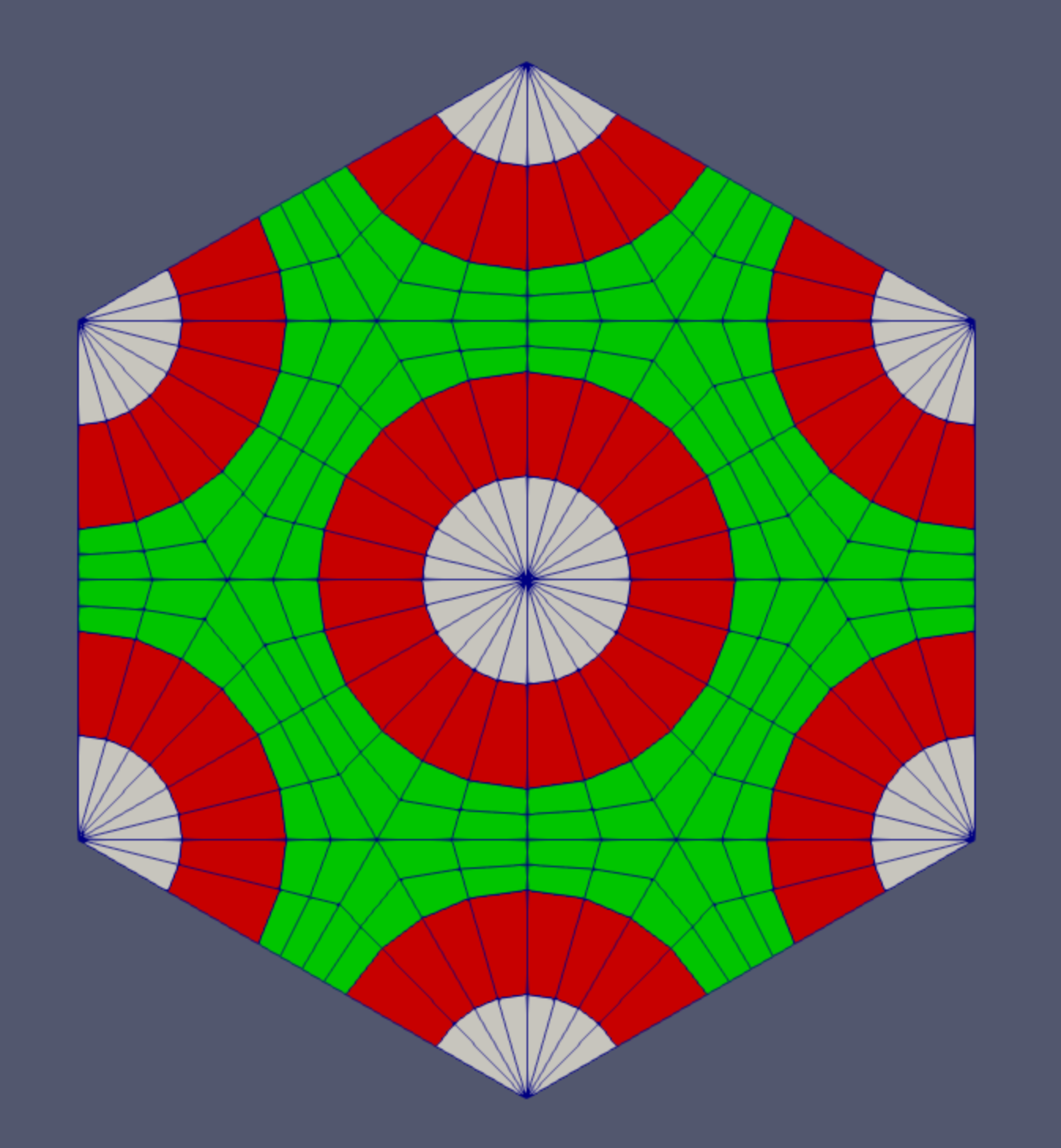
Figure 2: Mesh peripheral trimming example.
Listing 1: Mesh peripheral trimming example input.
[Mesh<<<{"href": "../../../syntax/Mesh/index.html"}>>>]
  [pattern_assm_peri_trim]
    type = HexagonMeshTrimmer<<<{"description": "This HexagonMeshTrimmer object performs peripheral and/or across-center (0, 0, 0) trimming for assembly or core 2D meshes generated by PatternedHexMG.", "href": "../../../source/meshgenerators/HexagonMeshTrimmer.html"}>>>
    input<<<{"description": "The input mesh that needs to be trimmed."}>>> = pattern_assm
    trim_peripheral_region<<<{"description": "Whether the peripheral region on each of the six sides will be trimmed in an assembly mesh. See documentation for numbering convention."}>>> = '1 1 1 1 1 1'
    peripheral_trimming_section_boundary<<<{"description": "Boundary formed by peripheral trimming."}>>> = peripheral_section
  []
[]Center Trimming Example
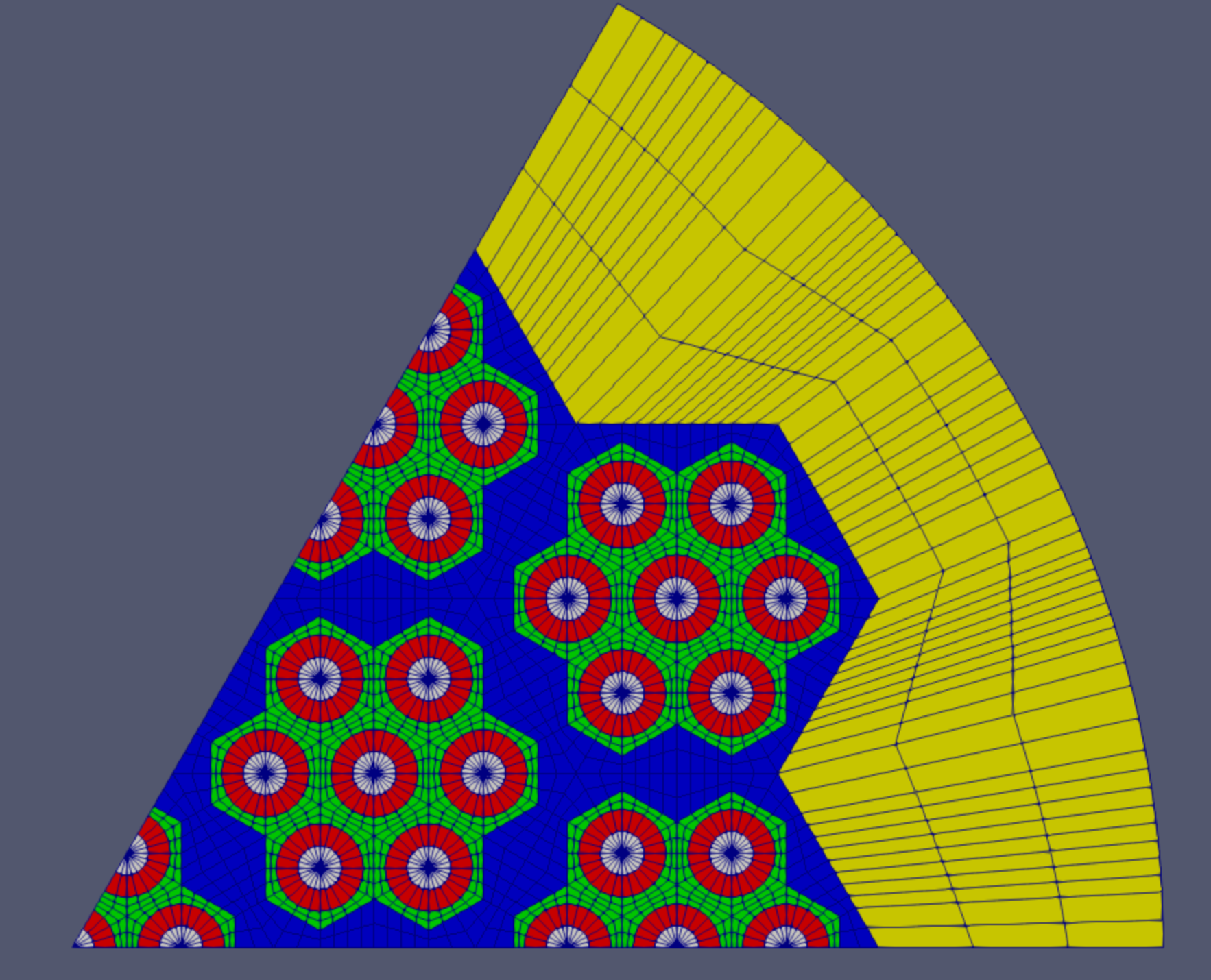
Figure 3: Mesh center trimming example.
Listing 2: Mesh center trimming example input.
[Mesh<<<{"href": "../../../syntax/Mesh/index.html"}>>>]
  [core_trim]
    type = HexagonMeshTrimmer<<<{"description": "This HexagonMeshTrimmer object performs peripheral and/or across-center (0, 0, 0) trimming for assembly or core 2D meshes generated by PatternedHexMG.", "href": "../../../source/meshgenerators/HexagonMeshTrimmer.html"}>>>
    input<<<{"description": "The input mesh that needs to be trimmed."}>>> = pr
    center_trim_starting_index<<<{"description": "Index of the starting center trimming position."}>>> = 0
    center_trim_ending_index<<<{"description": "Index of the ending center trimming position."}>>> = 2
    center_trimming_section_boundary<<<{"description": "Boundary formed by center trimming (external_boundary will be assigned if this parameter is not provided)."}>>> = symmetric
  []
[]Assembly Periphery Modification
Assemblies with identical pin numbers and discretizations can be easily stitched together using PatternedHexMeshGenerator. However, real reactor cores often contain assemblies of various types which have different numbers of pins (e.g., control assembly and fuel assembly). When the number of pins in neighboring assemblies does not match, the outer boundaries of these neighboring assemblies will in general not match each other unless the user increases the azimuthal discretization of each mesh until the two edges have the same node count. This procedure is undesirable as it can excessively refine the mesh beyond what is needed. PatternedHexPeripheralModifier is available to modify the boundary nodes of an existing assembly mesh to enforce a specific number of nodes (uniformly distributed) to facilitate stitching to neighboring assemblies. The mesh generator does this by changing the outermost layer of elements into a transition layer which either increases or decreases the number of nodes on the outer boundary.
Object
(Cartesian sibling – PatternedCartesianPeripheralModifier)
Geometry Features
Modify the peripheral region of an assembly mesh to enforce a given number of nodes uniformly distributed on the external boundary to facilitate the stitching of different assembly meshes.
Notes
The input mesh must be an assembly with a hexagonal boundary (coolant and/or duct region(s) present).
Example
![An example assembly mesh with its peripheral region modified by [PatternedHexPeripheralModifier.md].](../../../large_media/tutorials/tutorial04_meshing/base_ex_phpm.png)
Figure 4: An example assembly mesh with its peripheral region modified by PatternedHexPeripheralModifier.
Listing 3: Periphery modification example input.
[Mesh<<<{"href": "../../../syntax/Mesh/index.html"}>>>]
  [pattern_assm_peri_mod]
    type = PatternedHexPeripheralModifier<<<{"description": "PatternedPolygonPeripheralModifierBase is the base class for PatternedCartPeripheralModifier and PatternedHexPeripheralModifier.", "href": "../../../source/meshgenerators/PatternedHexPeripheralModifier.html"}>>>
    input<<<{"description": "The input mesh to be modified. Note that this generator only works with PatternedHex/CartesianMeshGenerator and its derived classes such as HexIDPatternedMeshGenerator."}>>> = pattern_assm
    input_mesh_external_boundary<<<{"description": "The external boundary of the input mesh."}>>> = 10000
    new_num_sector<<<{"description": "Number of sectors of each side for the new mesh."}>>> = 10
    num_layers<<<{"description": "Layers of elements for transition."}>>> = 2
  []
[]Extrusion to 3D
Many reactor geometries can be accurately described with extruded geometry in the axial direction. Extrusion from a 2D mesh to 3D is a very common mesh operation handled by AdvancedExtruderGenerator. The height of each layer, meshing control, subdomain IDs, and extra element integers can be specified by the user in this mesh generator to effectively generate a 3D mesh from a 2D one.
Object
Geometry Features
Extrudes a 1D mesh into 2D, or a 2D mesh into 3D
Can have a variable height for each elevation
Variable number of layers within each elevation
Variable growth factors of axial element sizes within each elevation
Remap subdomain IDs, boundary IDs and element extra integers within each elevation as well as interface boundaries between neighboring elevation layers.
Notes
Extrusion may be performed along any direction specified by an vector. Most common vector is which is the +-direction.
Example
![An example extruded mesh generated by [AdvancedExtruderGenerator.md] with subdomains swapped.](../../../large_media/tutorials/tutorial04_meshing/base_ex_aeg.png)
Figure 5: An example extruded mesh generated by AdvancedExtruderGenerator with subdomains swapped.
Listing 4: Advanced extrusion example input.
[Mesh<<<{"href": "../../../syntax/Mesh/index.html"}>>>]
  [core_ext]
    type = AdvancedExtruderGenerator<<<{"description": "Extrudes a 1D mesh into 2D, or a 2D mesh into 3D, and supports a variable height for each elevation, variable number of layers within each elevation, variable growth factors of axial element sizes within each elevation and remap subdomain_ids, boundary_ids and element extra integers within each elevation as well as interface boundaries between neighboring elevation layers, as well as following a 1D curve and modifying the radial (normal to the extrusion axis) extent of the geometry.", "href": "../../../source/meshgenerators/AdvancedExtruderGenerator.html"}>>>
    input<<<{"description": "The mesh to extrude"}>>> = core_trim
    heights<<<{"description": "The height of each elevation"}>>> = '30 60 30'
    num_layers<<<{"description": "The number of layers for each elevation - must be num_elevations in length!"}>>> = '2 3 2'
    direction<<<{"description": "A vector that points in the direction to extrude (note, this will be normalized internally - so don't worry about it here)"}>>> = '0 0 1'
    # Optional subdomain swap
    subdomain_swaps<<<{"description": "For each row, every two entries are interpreted as a pair of 'from' and 'to' to remap the subdomains for that elevation"}>>> = '10 100 15 150 20 150 80 150 300 150;
                        ;
                       10 200 15 250 20 250 80 250 300 250'
  []
[]