Introduction
In this tutorial, we will build a simple model of system with a primary loop and secondary side. In the primary loop, we will be circulating helium using a pump. We will be adding heat in the core section and removing it in the heat exchanger section. The secondary side will be running liquid water.
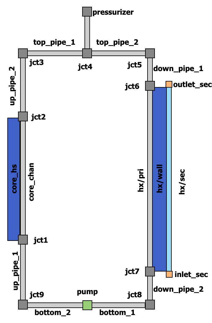
Figure 1: Diagram of the system
We will gradually build the model step by step introducing the following basic concepts:
Fluid property system
Components
Postprocessors
Control logic
Functions
Closure system
Each step will be a complete working model that will be simulating a subset of the final model.
Problem Description
Figure 1 shows the diagram of the modeled system. The tables below list its physical parameters.
Table 1: Primary loop parameters
| Parameter | Value (and unit) |
|---|---|
| Pressure | 1 MPa |
| Temperature | 300 K |
| Mass flow rate | 0.01 kg/s |
| Fluid | helium |
Table 2: Core parameters
| Parameter | Value and unit |
|---|---|
| Shape | Heating rod inside a square flow channel |
| Core length | 1 m |
| Side width | 8.7 cm |
| Rod diameter | 2. cm |
Table 3: Heat exchanger parameters
| Parameter | Value and unit |
|---|---|
| Inner diameter | 12 cm |
| Wall thickness | 5 mm |
| Outer diameter | 50 cm |
| Length | 1.5 m |
Table 4: Secondary loop parameters
| Parameter | Value and unit |
|---|---|
| Mass flow rate | 1 kg/s |
| Fluid | Liquid water |